Table of Contents
Advertisement
Quick Links
Advertisement
Table of Contents

Related Manuals for Spectra Precision HV302G


Summary of Contents for Spectra Precision HV302G
-
Page 2: Table Of Contents
TABLE OF CONTENTS Introduction For Your Safety Components How to Use the Laser System Powering the Laser Turning On/Off the Laser Laser Setup Standard Features Rotation Mode Scan Mode Manual Mode Y-/X-Single Slope Mode Mask mode Activating/Deactivating Standby Mode Operating Examples Determining the Height of Instrument (HI) Using the optional HL760/HL760U receiver Pairing the HL760/HL760U receiver with the transmitter... - Page 3 Special Features using the optional RC402N RC402N Features and Functions Powering the RC402N Turning On/Off the RC402N Radio Remote Control Pairing the remote control with the transmitter MENU Features at the RC402N Rotation Scan Automatic Grade Match Automatic PlaneLok Mask mode Line Scan (Vertical Setup) Beam Plunge (Vertical Setup) Setting Menu...
-
Page 4: For Your Safety
- Do not remove warning labels from the unit. - The HV302/HV302G is a class 3A/3R laser (<5 mW; 600 - 680 nm / G - 520 nm) IEC 60825-1:2007) - Never look into the laser beam or direct it to the eyes of other people. - Page 5 HV302/HV302G - Components...
-
Page 6: Components
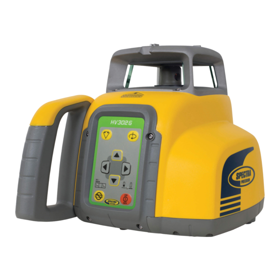
Components a Power Button b Battery LED k Sunshade c Manual/Standby Button l Sighting Guides d Leveling LED m Axes-Alignment-Marks e HI/Manual/Standby LED n Recharge Jack f Up and Down Arrow Buttons o Handle g Left and Right Arrow Buttons p Battery door h Rotation Button q 5/8 x 11 Tripod Mounts... - Page 7 Powering the HV302/HV302G 1 – HV302/HV302G is shipped with a rechargeable NiMH battery pack, it is keyed to prevent mis-insertion. 2 – The rechargeable battery pack can be charged inside of the unit 3 – Alkaline batteries can be used as a backup 4 –...
- Page 8 Recharging the Batteries Note: The battery LED shows the approximate charge of the batteries. The LED will flash when battery voltage is between 3.8 and 4.0 volts. The LED will be on continuously when battery voltage is less than 3.8 volts. The charger requires approx.
-
Page 9: Turning On/Off The Laser
Laser Setup Position the laser horizontally (tripod mount and rubber feet downward!) on a stable platform, wall mount or tripod at the desired elevation. The laser recognizes automatically whether it is used horizontally or vertically when switched on. Turning On/Off the laser Press the power button to turn On the laser. -
Page 10: Standard Features
Standard Features Rotation Mode Rotation speed can be selected using the Rotation button as well as using the RC402N menu. Repeatedly pressing the Rotation button toggles through 0, 10, 80, 200, 600 rpm regardless if the unit is in automatic or manual mode. At 0 rpm, the beam stops automatically close to the +Y- axis center position. When set up horizontally in automatic mode, using buttons Up/Down increases/decreases the rotor speed from 10 to 80 and then continuously in 10 rpm increments up to 600 rpm. -
Page 11: Manual Mode
Standard Features Manual mode Pressing and releasing Manual button activates/deactivates the manual mode regardless if set up horizontal or vertical. Manual mode is indicated by the flashing (once every second) red LED (e). In Manual mode (horizontal), the Y-axis can be sloped by pressing the Up and Down Arrow-buttons on the laser or remote control. -
Page 12: Mask Mode
Mask Mode Mask Mode – allows you to electronically turn off the rotating laser beam (electronic shutters) in up to 3 lighthouse windows to prevent interference with other receivers on the jobsite. Mask Mode can be selected as a standard feature as well as using the menu. To activate the mask mode on the + or -Y-axis, press the Up or Down arrow button at the laser or remote control, then within <1 second press and release the Manual button. - Page 13 Applications Interior Acoustical Ceilings Determine and mark the finished ceiling height and securely install the first piece of wall molding to this height. Attach the laser onto the wall molding by sliding the wall mount over the wall molding and turn the locking screws until the wall mount is secured. Make sure the locking knob on the wall mount is loose.
-
Page 14: Determining The Height Of Instrument (Hi)
Determining the Height of Instrument (HI) The height of instrument (HI) is the elevation of the laser’s beam. The HI is determined by adding the grade-rod reading to a benchmark or known elevation. Set up the laser and place the grade rod on a job-site benchmark (BM) or known elevation. Slide the receiver up/down the grade rod until it shows an on-grade reading. - Page 15 Using the Y-Axis Single Slope Mode Set up the laser and align it to the desired slope hub using the sighting guides on the sunshade. Check the laser beam elevation close to the laser. To activate the Y-axis single slope mode, press the manual mode button twice. The red and green LED flashes simultaneously (once a second).
-
Page 16: Using The Optional Hl760Hl760U Receiver
Using the optional HL760HL760U receiver To pair the HL760/HL760U receiver with the transmitter Make sure the transmitter is turned off. First, turn on the receiver, then press and hold the Deadband (A) and Audio (B) buttons for two seconds. After two seconds, the display shows MENU first, then RDIO Press and release the Units (C) button –... - Page 17 Special Features using the optional RC402N RC402N Features and Functions The remote control mirrors the basic functionality of the laser keypad and offers additional features using the M and E buttons. Battery status laser M-Button : Quickly press and release starts Mask mode indication the MENU entry and can be used to return to the previous menu position...
- Page 18 Powering the RC402N 1. Open the battery door using a coin or similar pry device to release the battery door tab on the RC402N. RC402N will be shipped with alkaline batteries Rechargeable batteries can be used optional but need to be charged externally. 2.
- Page 19 Press and release the Up/Down buttons until the desired function at the selected menu row is marked. Press and release button E to open the submenu OR start the selected function. Menu functions for the HV302/HV302G Horizontal Setup Vertical Setup...
- Page 20 Rotation Press and release the M button at the Standard Display and select >>Rotation<<. Press and release button E to display the actual rotation speed. Use the Up/Down buttons to select toggle through the pre-selected rotation speeds 0, 10, 80, 200 and 600 rpm. Confirm the desired speed by pressing the E button.
- Page 21 Automatic Grade Match The Grade Match mode can be activated in horizontal automatic mode. In Grade Match mode, the laser can be used to connect two known elevation points (up to 100 m (330 ft) located on the Y-axis of the laser. 1.
- Page 22 Automatic PlaneLok The PlaneLok mode can be activated in horizontal automatic and vertical automatic and manual mode. In PlaneLok mode when set up horizontal, the beam will be locked to a fixed elevation point (up to 100 m (330 ft) located on the Y-axis of the laser.
- Page 23 Note: In every PlaneLok mode the laser continues to servo to the receiver’s signals. Any loss of signal over an extended period of time (1 minute) causes the laser to go into the HI-alert condition (beam turns off, rotor stops and a warning message occurs at the RC402N LCD).
- Page 24 Mask mode Press and release the M button at the Standard Display and select >>Mask Mode<<. Depending on which side the beam should be turned off, the required side can be selected. Press and release the E button, the mask symbol occurs. For selecting the side, press and release one of the arrow button.
- Page 25 Service Press and release the M button at the Standard Display and select >>Service<<. Buttons Up/Down can be used to toggle between Calibration X and Calibration Y OR Calibration Z when set up vertically. Press and release button E to confirm the selection. The calibration at the selected axis starts the field calibration procedure.
- Page 26 Sensitivity Selection Select >>Sensitivity<< and press and release button E to open the Sensitivity menu. The desired Sensitivity: Low, Mid (Default) and High) can be selected using the Up/Down buttons. Press and release button E to confirm the selected Sensitivity. Select Language Select >>Language<<...
- Page 27 Troubleshooting Any error message can be deleted with a short press of button E. The table shows the related description and possible solutions. The next service center should be contacted if a different error message as shown at the table will be displayed.
- Page 28 CALIBRATION Checking Calibration of the Y- and X-Axes 1. Set up the laser 30 m (100 ft) from a wall and allow it to level. 2. Allow the unit to warm up for 20 minutes. 3. Raise/lower the receiver until you get an on-grade reading for the +Y axis.
- Page 29 Wall Mount Nail Holes (3) – allows you to hang the wall mount onto nails or screws. Locking Screws – lock/unlock the wall mount at the wall molding or floor track. Locking Knob—tightens/loosens the sliding bracket in place after it has been positioned along the elevation scale.
- Page 30 PROTECTING THE UNIT Do not expose the unit to extreme temperatures or temperature changes (do not leave inside the car). The unit is very robust and can resist damage if dropped even from tripod height. Before continuing your work, always check the leveling accuracy. See Checking Calibration section. The laser is water proof and can be used indoors and outdoors.
- Page 31 Trimble warrants the HV302 to be free of defects in material and workmanship for a period of five years (HV302G three years). Trimble or its authorized service center will repair or replace, at its option, any defective part, or the entire product, for which notice has been given during the warranty period. If required,...
- Page 32 Battery life HV302/HV302G: 45/30 hours NiMH; 60/45 hours alkaline Operating temp.: HV302: -20°C to 50°C (-4°F to 122°F) HV302G: 0°C to +40°C (32°F to 104°F) Storage temp.: -20°C to 70°C (-4°F to 158°F) Tripod attachments: 5/8 x 11 horizontally and vertically...
- Page 33 Following is the valid declaration: Trimble Kaiserslautern GmbH Declare under our sole responsibility that the products HV302/HV302G and RC402N to which this declaration relates is in conformity with the following standards: EN300 440-2 V1.1.1:2004, EN301 489-03 V1.4.1:2002, EN301 489-01 V1.4.1:2002, EN50371:2002 following the provisions of directive R&TTE 1999/5/EC...
- Page 34 This in particular is applicable for the antenna which has been delivered with the HV302/HV302G and RC402N Under Industry Canada regulations, this radio transmitter may only operate using an antenna of a type and maximum (or lesser) gain approved for the transmitter by Industry Canada.
Need help?
Do you have a question about the HV302G and is the answer not in the manual?
Questions and answers