Table of Contents
Advertisement
Quick Links
Advertisement
Table of Contents

Related Manuals for Spectra Precision FOCUS 30


Summary of Contents for Spectra Precision FOCUS 30
- Page 1 Spectra preciSion ® 30 TOTAL STATION USER GUIDE...
- Page 3 User Guide Spectra Precision FOCUS 30 Total Station Version 01.02 Part Number 77701035 February 2010...
- Page 4 Menlo Worldwide Logistics This is the February 2010 release version 01.02 of the Meerheide 45 Spectra Precision FOCUS 30 User Guide, Part Number 77701035. It 5521 DZ Eersel, NL applies to the Spectra Precision FOCUS 30 total station. The following limited warranties give you specific legal rights. You Class A Statement –...
-
Page 5: Laser Safety
Before using the instrument, make sure that you understand this user guide, as well as all equipment and job site safety requirements. Safety Information • Instruments and original accessories from Spectra Precision must only be used for the intended purpose. • Operate the instrument only in the compliance with the operating conditions specified. -
Page 6: Queries
Phone (937) 233-8921 ext 824 or (800) 538-7800 Fax (937) 233-9661 Spectra Precision FOCUS 30 Total Station The Spectra Precision FOCUS 30 Total Station is a CLASS 3R LASER PRODUCT and contains different light sources. Distance Measurement and Laser Pointer The Distance Measuring Unit in reflectorless mode and in Laser Pointer mode pro- duces visible Laser light emerging at the centre of the telescope objective. - Page 7 Warning – The use of Laser Class 3R equipment can be dangerous for the eyes. The risk for eye damage is minimized through the radiation limit of 5 mW (FOCUS 30 at 660 nm). Do not stare directly into the beam.
-
Page 8: Tracklight
144 s Pulse duration Max. pulse frequency 109 Hz Max. Peak Power 2.22 mW Max. Mean Power 0.035 mW Wavelength 850 nm Measuring uncertainty ± 5 % For instrument labeling, see Laser Information, page 30 Spectra Precision FOCUS 30 User Guide... -
Page 9: Battery Safety
Do not charge or use the battery if it appears to be damaged or leaking. • Charge the lithium-ion battery only in a Spectra Precision product that is specified to charge it. Be sure to follow all instructions that are provided with the battery charger. -
Page 10: Environmental Information
That is why Spectra Precision is actively pur- suing, and will continue to pursue, the expanded use of... -
Page 11: Declaration Of Conformity
Declaration of Conformity Spectra Precision FOCUS 30 User Guide... - Page 12 Declaration of Conformity Spectra Precision FOCUS 30 User Guide...
-
Page 13: Table Of Contents
Queries ..........................IV Spectra Precision FOCUS 30 Total Station ....Distance Measurement and Laser Pointer ........IV Tracklight . - Page 14 Laser Information ......................30 Spectra Precision FOCUS 30 Total Station ....... . 30 4 Setup .
- Page 15 Spectra Precision Extra Sighting Target ........94...
- Page 16 Table of Contents Spectra Precision FOCUS 30 User Guide P/N 77701035, Version 1.02...
-
Page 17: Introduction
C H A P T E R Introduction In this chapter Welcome Related Information Technical Assistance Registration Spectra Precision FOCUS 30 User Guide... -
Page 18: Welcome
Welcome to the Spectra Precision FOCUS 30 Total Station user guide. This manual describes how to setup and use the Spectra Precision FOCUS 30 Total Station. Even if you have used an optical Total Station before, Spectra Precision recommends that you spend some time reading this manual to learn about the special features of this product. -
Page 19: Inspection Care And Maintenance
C H A P T E R Inspection Care and Maintenance In this chapter Inspecting the Container Instrument Case Care and Maintenance Transporting the Instrument Servicing Spectra Precision FOCUS 30 User Guide... -
Page 20: Inspecting The Container
Inspect the shipping container. If the container arrives in poor condition, examine the equipment for visible damage. If damage is found, immediately notify the carrier and your Spectra Precision sales representative. Keep the container and the packing mate- rial for the carrier to inspect. - Page 21 2 Inspection Care and Maintenance Items in the case: 1. Spectra Precision FOCUS 30 instrument 2. Instrument rain cover 3. Instrument case keys (x2) 4. User guide CD; Warranty Card; WEEE information; Certificate 5. Allen key for optical plummet (1.3mm), Allen key for EDM/Coarse sight (1.5mm) and adjustment key for tribrach bubble 6.
-
Page 22: Instrument Versions
FOCUS 30 LockNGo 2" 873xxxxx 78204035 FOCUS 30 LockNGo 3" 874xxxxx 78205035 FOCUS 30 LockNGo 5" 875xxxxx 78206035 FOCUS 30 StepDrive 2" 876xxxxx 78207035 FOCUS 30 StepDrive 3" 877xxxxx 78208035 FOCUS 30 StepDrive 5" 878xxxxx Spectra Precision FOCUS 30 User Guide... -
Page 23: Care And Maintenance
The Spectra Precision FOCUS 30 Total Station is designed and tested to withstand field conditions, but like all precision instruments, it requires care and maintenance. -
Page 24: Applying A Screen Protector For The Face1 Screen
Leave the instrument to dry natu- rally. If condensation forms on the lenses, allow the moisture to evaporate naturally. Leave the carrying case open until all moisture has evaporated. Spectra Precision FOCUS 30 User Guide... -
Page 25: Transporting The Instrument
Always transport the instrument in a locked instrument case. For longer trips, trans- port the instrument in the instrument case and inside the original shipping container. Servicing There are no user-serviceable parts on the Spectra Precision FOCUS 30 Note – Total Station. - Page 26 2 Inspection Care and Maintenance Spectra Precision FOCUS 30 User Guide...
-
Page 27: Getting Started
C H A P T E R Getting Started In this chapter Power Supply Instrument Description Connecting the Instrument to an Office Computer Laser Information Spectra Precision FOCUS 30 User Guide... -
Page 28: Power Supply
Do not charge or use the battery if it appears to be damaged or leaking. • Charge the lithium-ion battery only in a Spectra Precision product that is specified to charge it. Be sure to follow all instructions that are provided with the battery charger. -
Page 29: Checking The Instrument Battery Power Supply
Environmental Information, page VIII. Checking the Instrument Battery Power Supply To check the power supply in the Spectra Precision FOCUS 30 Total Station battery using the built in battery gauge, press the button on the side of the battery, see Figure 3-1. - Page 30 Charge the battery before using the total station if the equipment has been stored for longer than six months. Fig. 3-2 Battery charger 53021010-SPN for instrument and radio battery Via country specific Radio Battery adapter to mains power AC/DC Converter Instrument Battery DC Input Spectra Precision FOCUS 30 User Guide...
-
Page 31: Inserting The Battery
3 Getting Started Inserting the Battery The Spectra Precision FOCUS 30 Total Station internal battery fits into the battery compartment on the side of the instrument. This battery can easily be removed and replaced. To insert the battery: Open the battery compartment door, by pressing gently on the battery release button. -
Page 32: Suspend Mode
Note – controller has to reboot when it restarts. If the Spectra Precision FOCUS 30 Total Station has not been restarted when the sus- pend period (default 120 minutes) has elapsed, the instrument powers down and has to reboot when started again. -
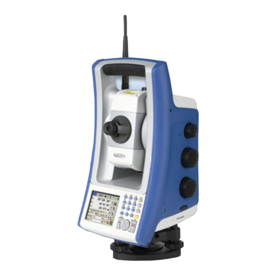
Page 33: Instrument Description
Figure 3-4 Figure 3-5. Fig. 3-4 Operator’s view of the Spectra Precision FOCUS 30 Total Station Coarse sight Focusing Eyepiece servo knob Vertical motion... - Page 34 3 Getting Started Fig. 3-5 Front view of the Spectra Precision FOCUS 30 Total Station Radio antenna Coaxial optics for angle and distance measurements, tracker and laser pointer Optics for Compartment for tracklight instrument battery Face2 Optical plummet Control Unit...
-
Page 35: Optical Plummet
Trigger Key The trigger key functions as an On/Off key (z). A LED in the trigger key indi- cates if the instrument is turned on. A solid light indicates On and a flashing light Spectra Precision FOCUS 30 User Guide... -
Page 36: Control Unit Face1
123, ABC, and abc. Multiple presses on one key scroll through the letters on that key depending on which state you’re in. Fig. 3-8 Control Unit Face1 Quick Shot Menu Measurement 1 Measurement 2 Spectra Precision FOCUS 30 User Guide... - Page 37 Switch to level bubble - in field software only Pop up the Windows taskbar Enter a “-” or a “+” symbol Delete Operating System The Spectra Precision FOCUS 30 Total Station runs the operating system: ® ® Microsoft Windows CE .Net...
- Page 38 Input Panel appears or is tapped. To change the default use the Input Panel icon at the CE Taskbar or tap the Start menu and select Settings/Control Panel/Input Panel and choose the desired option. Spectra Precision FOCUS 30 User Guide...
- Page 39 Change the date and time as required. To accept the new settings, tap OK. To cancel, tap B. ® when you attach the instrument to your computer using Microsoft Note – ® ActiveSync technology, time and date are automatically updated. Spectra Precision FOCUS 30 User Guide...
-
Page 40: Control Unit Face2
When the field software is running, the trigger key performs the same function Note – as the Measurement1 key ( ) on the Face1 side and the Enter key ( ) at the Face2 side. Spectra Precision FOCUS 30 User Guide... -
Page 41: Objective Rain Cover
Caution – Dust and rain can have an effect on the distance measurements, please keep objective front lens and the targeting prism clean and use the objective rain cover. Fig. 3-12 Objective Rain Cover Spectra Precision FOCUS 30 User Guide... -
Page 42: Connecting The Instrument To An Office Computer
ActiveSync and Windows Mobile Device Center (WMDC) provide an easy way to synchronize data on a Windows-based computer with your FOCUS 30 Total Sta- tion. ActiveSync works on computers that have Windows XP or earlier operating ® systems. WMDC works only on computers that have Windows Vista or Windows 7. -
Page 43: Setting Up And Running Activesync
3 Getting Started Setting Up and Running ActiveSync Please use the Hirose-USB cable (73840019) to connect the Spectra Precision FOCUS 30 Total Station with a USB port of your computer. The instrument will switch on automatically. Follow these steps: Program ActiveSync starts automatically, please follow the dialog. - Page 44 Click Finish in the Setup Complete dialog. ActiveSync opens. To view the files on the Instrument, click the Explorer icon. The file structure looks and functions the same as Windows Explorer on your computer. Spectra Precision FOCUS 30 User Guide...
-
Page 45: Disconnecting Activesync
Tip – You have to wait a few seconds until the next screen appears. Tap Disconnect and then remove the cable: For more information about ActiveSync, refer to the help or visit the Microsoft web- site. Spectra Precision FOCUS 30 User Guide... -
Page 46: Laser Information
Laser Safety, page III Spectra Precision FOCUS 30 Total Station The Spectra Precision FOCUS 30 distance measuring unit and Laser Pointer has been tested and complies with the regulations for a CLASS 3R LASER PRODUCT. Fig. 3-13 Spectra Precision FOCUS 30 Total Station... - Page 47 3-14. The laser aperture label is located on one side of the telescope close to the objective, see Figure 3-16 Fig. 3-14 Location of Laser warning label on a Spectra Precision FOCUS 30 Total Station Fig. 3-15 Distance Measurement Unit and Laser Pointer warning label LASER RADIATION...
- Page 48 3 Getting Started Fig. 3-16 Location of Laser aperture label on a Spectra Precision FOCUS 30 Total Station Fig. 3-17 Laser aperture label Spectra Precision FOCUS 30 User Guide...
-
Page 49: Setup
C H A P T E R Setup In this chapter Setup Starting the Instrument Instrument Adjustment and Calibration Measuring the Instrument Height Pre Measurement Check List Connecting to an External Control Unit Spectra Precision FOCUS 30 User Guide... -
Page 50: Setup
Make sure that all the screws on the tripod and/or tribrach are tightened to avoid any play. Any high quality tripod and tribrach can be used. However, Spectra Precision strongly recommends the use of tripod heads made of steel, aluminium or similar material. -
Page 51: Measurement Stability
Temperature difference in degree Celsius (°C) x 2 = duration in minutes required for the instrument to adjust to the new temperature. Avoid sighting across fields with intense heat shimmer by sun light, e.g. at noon. Spectra Precision FOCUS 30 User Guide... -
Page 52: Starting The Instrument
It is recommended especially if you want to work in Robotic mode. • When Windows CE has started select your field software from the start menu. ™ Please refer to your Spectra Precision Survey Pro documentation for supplementary information. Fig. 4-2 Starting instrument... -
Page 53: Starting And Settings Via Face1 Control Unit
Actions and Comments Fig. 4-3 Face1 screen after instrument start While starting Windows CE the Spectra Precision logo screen will show for several seconds and then the menu to work in Windows CE will appear. Fig. 4-4 Face1 screen after starting Windows CE Start the software Spectra Precision Survey Pro by tapping the Survey Pro icon. -
Page 54: First Steps In Spectra Precision Survey Pro
4 Setup First Steps in Spectra Precision Survey Pro Spectra Precision recommends spending some time reading the Spectra Precision Survey Pro User Manual to learn details of the application program. This subchapter describes a brief overview. Quick Shot Menu After confirming the Level Bubble menu the screen shows the Quick Shot menu. - Page 55 Lookup and register Software Screen Actions and Comments Fig. 4-9 Registration Modules menu After the initial start of Spectra Precision Survey Pro, the following menu will appear. Please select Register Modules and enter your registration code(s). Fig. 4-10 How to enter codes Please use the keyboard on the screen to enter registration code.
- Page 56 Screen Actions and Comments Fig. 4-12 Main Menu Spectra Precision Survey Pro Select menu File and the appropriate menu items appear on the screen - e.g. Open /New. Fig. 4-13 Menu to work with jobs Select a file with Open or create a New Job with New.
- Page 57 Select menu File and menu element About and the software version appears on the screen. Fig. 4-15 Survey Pro Version Press the ESC button and the program will return automatically to the Main Menu. Spectra Precision FOCUS 30 User Guide...
- Page 58 4 Setup Settings Face2 Display Backlight, Reticle Illumination and Tracklight Screen Actions and Comments Fig. 4-16 Main Menu Spectra Precision Survey Pro Select instrument Settings by tapping on this icon. Fig. 4-17 Menu for Settings Navigate to Lights via drop down menu or toggle through the submenus with D key left or right.
-
Page 59: Starting And Settings Via Face2 Control Unit
2. Second function - on screen symbols Network ID: – N - Leveling Menu – P - Instrument Settings StepDrive motor system and Focus system are usable while the Instrument Note – Status menu shows Waiting. Spectra Precision FOCUS 30 User Guide... - Page 60 Unit Face1 started, this field software controls the Face2 display. While using the field software in every menu the Main Menu from the Face2 display can be opened with a long P key press! Spectra Precision FOCUS 30 User Guide...
- Page 61 4 Setup Face2 Display while using Spectra Precision Survey Pro in different Instrument Versions StepDrive and LockNGo: If the field software at Control Unit Face1 is started, the field software controls the Face2 display. Screen Actions and Comments Fig. 4-24 F2 Display while controlled via F1 program The Face2 display always shows measurement results parallel to the Face1 Control Unit.
- Page 62 Adjust the contrast by pressing N or O. Contrast: Confirm the selection with P Contrast range: 0 - 256 Setting function for brightness and contrast is in every F2 menu available. Note – Spectra Precision FOCUS 30 User Guide...
-
Page 63: Main Menu Face2 - Information And Settings
Level bubble Confirm a selection by pressing the P key. Instrument details The Main Menu is structured as follows Setting Page Exit Radio Parameter page 48 Instrument details page 49 Service menu page 50 Spectra Precision FOCUS 30 User Guide... - Page 64 Network ID Network ID: with the same procedure. When last digit of Network ID is confirmed, the system jumps back to the Main Menu. Radio channel range: 1- 30 Network ID range: 0 - 255 Spectra Precision FOCUS 30 User Guide...
- Page 65 Instrument Details and then press P. Level Bubble Instrument Details Fig. 4-33 Instrument Details Instrument Details FOCUS 30 Robotic 2” Leave the menu by pressing the P key. Your definition Serial: 87000002 FWVer: R01.00 Spectra Precision FOCUS 30 User Guide...
- Page 66 USB Interface press P. Ext.EDM Calibr. Fig. 4-36 Service Menu USB Interface USB Interface Exit Always Off Tip – Please make sure that the USB Always On interface default setting is “Always Off” Temporary On Spectra Precision FOCUS 30 User Guide...
- Page 67 When last digit of Offset is confirmed, the system jumps back with the cursor to the inverse P key. Press P key a further time and the system jumps to Service Menu. Spectra Precision FOCUS 30 User Guide...
-
Page 68: Instrument Adjustment And Calibration
• Routinely on a periodic basis (Monthly, weekly etc.) Spectra Precision also recommends that the operator keep a record of the dates and values measured so that any gross changes can easily be detected. Gross changes can indicate the need for a check by an approved service center. -
Page 69: Optical (Ha/Va) Collimation And Trunnion Axis Tilt
100 m. The prism target must be very still during the test (Spectra Precision recommends that you use a tripod or bipod mount for the target) and must be in clear line of sight without any obstructing traffic. -
Page 70: Adjustment Routines In Survey Pro
4 Setup Adjustment Routines in Survey Pro Start the application program Spectra Precision Survey Pro. During the process the instrument should be on a stable platform. Screen Actions and Comments Fig. 4-39 Main Menu Spectra Precision Survey Pro Select instrument Settings by tapping on this icon Fig. - Page 71 Fig. 4-43 Optical Collimation / Trunnion Axis Decide per the displayed information for trunnion axis tilt collimation or confirm and store the new values for optical collimation. Spectra Precision FOCUS 30 User Guide...
- Page 72 Make sure to measure with the stated conditions. Fig. 4-45 Compensator Collimation start scree Make the measurements per the displayed information. During the process the instrument should be free from vibration and untouched by the user. Spectra Precision FOCUS 30 User Guide...
-
Page 73: The Laser Pointer
4 Setup The Laser Pointer The Spectra Precision FOCUS 30 Total Station uses a red laser beam to measure and as a Laser Pointer. The Laser Pointer is coaxial with the line of sight of the telescope. If the instrument is well adjusted, the red Laser Pointer coincides with the line of sight. - Page 74 Horizontal pointer Vertical pointer adjustment port adjustment port To correct the vertical position of the laser spot, insert the allen key into the vertical adjustment port and turn it as shown in Figure 4-48. Spectra Precision FOCUS 30 User Guide...
- Page 75 Fig. 4-48 Vertical adjustment directions Counter clockwise = up Clockwise = down To correct the horizontal position of the laser spot, insert the allen key into the horizontal adjustment port and turn it as shown in Figure 4-49. Spectra Precision FOCUS 30 User Guide...
- Page 76 Refit the plugs in the adjustment holes. Make sure that the plugs are correctly fitted for proper sealing against the cover. Caution – To keep out moisture and dust, make sure that the plugs are correctly fitted in the adjustment ports. Spectra Precision FOCUS 30 User Guide...
-
Page 77: Optical Plummet
Do not overtighten the screws, this might damage the optics. Fig. 4-50 Optical plummet adjustment Optical plummet reticle 4x adjustment screws Ground mark Spectra Precision FOCUS 30 User Guide... -
Page 78: Tribrach Circular Level
When one screw is adjusted the two opposite screw must be adjusted equally in the reverse direction, in order to keep the correct ten- sion on the Circular level. Do not overtighten the screws. Spectra Precision FOCUS 30 User Guide... -
Page 79: Measuring The Instrument Height
The bottom mark is 0.158 m (0.518 ft) below the top mark. Measure the bottom mark to the top ridge of the mark, see Figure 4-52. Fig. 4-52 Instrument height marks Top mark Bottom mark Spectra Precision FOCUS 30 User Guide... - Page 80 4 Setup When the Spectra Precision Survey Pro is running, the software has additional func- tions that reduce the bottom mark measurement to the required vertical instrument height to the trunnion axis, see Figure 4-53 and the following paragraph. Fig. 4-53 Instrument height measurement 0.158m...
-
Page 81: Pre Measurement Check List
Laser Pointer beam alignment • Correct radio channel is selected (robotic measurements only) • Measure instrument height • Allow sufficient time for the instrument to adjust to the ambient temperature, Setup Stability, page 34 Spectra Precision FOCUS 30 User Guide... -
Page 82: Connecting To An External Control Unit
Spectra Precision FOCUS 30 Total Station. The controller can be connected to the Spectra Precision FOCUS 30 Total Station via cable or via radio. Connecting with Cable - Instrument Version StepDrive and LockNGo The controller is connected from the Spectra Precision FOCUS 30 Total Station com port to the USB or the RS232 connector. -
Page 83: Connecting With Radio - Instrument Version Robotic
Connecting with Radio - Instrument Version Robotic The controller is connected directly to the instrument via the internal in radio. Fig. 4-55 External controller connected to the Spectra Precision FOCUS 30 Total Station using the radio for robotic measurements. Ranger with radio (option) - Page 84 4 Setup Spectra Precision FOCUS 30 User Guide...
-
Page 85: Instrument Operation Methods
C H A P T E R Instrument Operation Methods In this chapter Introduction Conventional Measurements with StepDrive Motor System LockNGo Measurement Robotic Measurement Spectra Precision FOCUS 30 User Guide... -
Page 86: Introduction
5 Instrument Operation Methods Introduction This chapter describes the following instrument operational methods for the Spectra Precision FOCUS 30 Total Station: • Conventional measurement with StepDrive motor system • LockNGo measurement • Robotic measurement Conventional Measurements with StepDrive Motor System... -
Page 87: Robotic Measurement
Combining the StepDrive motor capability with the image based tracking system and the radio capability enables the instrument to carry out measurements robotically. This enables a single operator to control the instrument and carry out measurements or set/stakeout from the rod at the point. Spectra Precision FOCUS 30 User Guide... - Page 88 5 Instrument Operation Methods Spectra Precision FOCUS 30 User Guide...
-
Page 89: Instrument Technology
Instrument Technology In this chapter Angle Measuring Technology Distance Measuring Technology Tracklight StepDrive Motor System and Focus system LockNGo Tracking Technology Power Management Power Supply External Communication Spectra Precision FOCUS 30 User Guide... -
Page 90: Angle Measuring Technology
Trunnion axis tilt, see Correction for Trunnion Axis, page Correction for Mislevelment The Spectra Precision FOCUS 30 Total Station automatically corrects for mislevel- ments up to ±5,5’. The instrument warns the operator immediately of any mislevel- ments in excess of ±5,5’(±0.1 grads). -
Page 91: Correction For Collimation Errors
Traditionally, collimation errors were eliminated by observing angles in both instru- ment faces. In the Spectra Precision FOCUS 30 Total Station, a pre-measurement col- limation test is performed to determine the collimation errors. Angular measurements are observed in both instrument faces, the collimation errors are calculated, and the respective correction values are stored in the instrument. -
Page 92: Correction For Trunnion Axis
Trunnion axis tilt error In the Spectra Precision FOCUS 30 Total Station, perform a pre-measurement trun- nion axis tilt test to determine the trunnion axis tilt error. Angular measurements are observed in both instrument faces, the trunnion axis tilt error is calculated, and the respective correction value is stored in the instrument. -
Page 93: Averaging Measurements To Reduce Sighting Errors
6 Instrument Technology Averaging Measurements to Reduce Sighting Errors The Spectra Precision FOCUS 30 Total Station automatically reduces sighting errors caused by the misalignment of the instrument to the target or by pole movement dur- ing measurement. The following techniques can be used: •... -
Page 94: Distance Measuring Technology
6 Instrument Technology Distance Measuring Technology Spectra Precision FOCUS 30 Total Stations are equipped with a combined distance unit. This means that the instrument can measure to a prism or to normal surfaces (reflectorless mode). The laser distance unit is based on the phase comparison method. The distance unit is... - Page 95 With a smaller measuring area, these small objects can be easily missed. A smaller measuring area has advantages when measuring tight corners and vertices at close range. When observing measurements to a tight corner, the distance meter beam Spectra Precision FOCUS 30 User Guide...
- Page 96 Do the following; Measure two points on the face of the building. Aim the instrument at the corner to store the correct horizontal and vertical angle, see Figure 6-4. Spectra Precision FOCUS 30 User Guide...
- Page 97 Point 1 Point 2 Point 3 With offset measurements, you can accurately measure difficult locations in reflector- less mode and eliminate beam divergence errors. For more information, refer to the field application software documentation. Spectra Precision FOCUS 30 User Guide...
-
Page 98: Tracklight
Figure 6-5. Fig. 6-5 Tracklight Green light Red light Tip – You can use the tracklight for clearing sight lines and as an aid to find prisms in the dark or unfavorable sighting conditions. Spectra Precision FOCUS 30 User Guide... -
Page 99: Stepdrive Motor System And Focus System
6 Instrument Technology StepDrive Motor System and Focus system Spectra Precision FOCUS 30 Total Station is equipped with a StepDrive motor sys- tem to position the instrument and the telescope and a servo drive to focus the tele- scope. Due to the instrument accuracy it is important to use a high quality tripod and tri- brach. - Page 100 LockNGo Tracker technology for robotic surveying, see Figure 6-7 Fig. 6-7 Position StepDrive motion knobs Vertical motion knob Down Horizontal motion knob Right Left Spectra Precision FOCUS 30 User Guide...
-
Page 101: Focus System
The focus knob is connected to a servo motor that is built into the telescope. When you turn the focus motion knob, the servo motor adjusts the focusing lens, see Figure 6-8. Fig. 6-8 Focus servo Focus motion knob Spectra Precision FOCUS 30 User Guide... -
Page 102: Lockngo Tracking Technology
Tip – To assure maximum performance from the LockNGo tracking technology keep the lens clean and dry. Fig. 6-9 The Spectra Precision FOCUS 30 Total Station LockNGo tracking function. The Spectra Precision FOCUS 30 Total Station can lock onto and track a prism Spectra Precision FOCUS 30 User Guide... -
Page 103: Power Management
6 Instrument Technology Power Management The power management in the Spectra Precision FOCUS 30 Total Station instrument can set the instrument to one of three different modes. • Off Mode • On Mode - all instrument functions • Suspend Mode - to save power and replace empty battery Saving power is also the possible with an economical use of the Control Unit Note –... -
Page 104: Robotic Configuration
Without replacing the battery the instrument will go to Off Mode if the battery capacity is less than 2 %. For Control Unit On/Off and Power save mode please read the appropriate Note – User Guides. Spectra Precision FOCUS 30 User Guide... -
Page 105: Power Supply
External Power Supply The Spectra Precision FOCUS 30 Total Station has one external port in the base of the instrument for communication and for external power supply. External power can be provided by a car battery(12V) with an appropriate cable. -
Page 106: External Communication
The communication port on the base of the Spectra Precision FOCUS 30 Total Station can be used for external communications to a computer or data collector. Caution – Use only the gray cables with 6-pin Hirose connectors from Spectra Precision when connecting a cable to the instrument. -
Page 107: Accessories And Options
Accessories and Options In this chapter Rod and Prisms Robotic Components GeoLock Cables for External Power Supply and Data Transfer Control Unit Screen Protector Telescope Accessories Transport Case Accessories Spectra Precision FOCUS 30 User Guide... -
Page 108: Rod And Prisms
7 Accessories and Options Rod and Prisms Spectra Precision Standard Rod The Spectra Precision standard rod is available with the Spectra Precision FOCUS 30 Total Station. The rod contains the following features: • Graduated scale in Meter and Feet. •... -
Page 109: Spectra Precision 360 Degree Prism
Spectra Precision 360 Degree Prism 360° prism comprising 7x25 mm prisms, h:135 mm, prism constant 2 mm. While using this prism adapter the height can be directly determined at the Spectra Precision standard rod. Fig. 7-2 360 Degree prism including height adapter (58128001-SPN) -
Page 110: Spectra Precision Standard Prism
Prism -Backside prism, h:135 mm prism constant:-35 mm. While using this prism the height can be directly determined at the standard rod. Fig. 7-3 SP Standard prism (78082035) Spectra Precision Extra Sighting Target Extra sighting target for backside prism. Fig. 7-4 Standard prism target plate (78084035) Spectra Precision FOCUS 30 User Guide... -
Page 111: Robotic Components
Radio implemented in external CU like Spectra Precision Ranger (optional) • Separate external radio used with Spectra Precision Nomad and Spectra Precision Recon consists of Controller radio and cable - see picture below. Fig. 7-5 Robotic Rod Spectra Precision FOCUS 30 User Guide... -
Page 112: Control Units And Accessories
7 Accessories and Options Control Units and Accessories Spectra Precision Recon Fig. 7-6 Recon Spectra Precision Nomad Fig. 7-7 Nomad Spectra Precision Ranger Fig. 7-8 Ranger (Radio - Option) Spectra Precision FOCUS 30 User Guide... - Page 113 7 Accessories and Options Bracket for adapting Spectra Precision Control Units Bracket for adapting Spectra Precision Recon at Spectra Precision Standard Rod Fig. 7-9 Recon Range Pole Bracket (58959-00) Bracket for adapting Spectra Precision Nomad at Spectra Precision Standard Rod.
-
Page 114: External Radio
Fig. 7-12 External radio 2.4 GHz (58050019-SPN) Indicator LED Battery COM Port For information regarding charging of the battery, see Charging the Instrument and the Radio Batteries, page Caution – Always remove the battery from the external radio after use. Spectra Precision FOCUS 30 User Guide... - Page 115 Fig. 7-13 How to clip on the battery (1) Push the battery downwards until the catch clicks in place. Fig. 7-14 How to clip on the battery (2) Click Click 3. 3. 2. 2. Spectra Precision FOCUS 30 User Guide...
- Page 116 Slide the battery upwards. Fig. 7-15 How to clip off the battery (1) Pull the battery away from the battery holder. Fig. 7-16 How to clip off the battery (2) 3. 3. 10 0 Spectra Precision FOCUS 30 User Guide...
- Page 117 7 Accessories and Options Cable between CU and Radio Fig. 7-17 Cable between CU and radio (53009012) Spectra Precision FOCUS 30 User Guide 1 01...
-
Page 118: Geolock
The technology greatly reduces the time to locate and lock onto a target. The Spectra Precision GeoLock technique combines a GNSS position with the FOCUS 30 robotic total station and the robotic roving operator. The remote instru- ment can then be directed towards the robotic roving operator using the GNSS posi- tion and a subsequent search is quickly performed to reacquire the target at the robotic rover. -
Page 119: Cables For External Power Supply And Data Transfer
Cable from instrument to PC with Hirose 6 pin and USB A plug. Fig. 7-19 Cable (73840019) - 2.5 m Cable from instrument to USB flash card memory with Hirose 6 pin and USB A socket A. Fig. 7-20 Cable (73841019) - 0.18 m Spectra Precision FOCUS 30 User Guide 1 03... -
Page 120: Control Unit Screen Protector
7 Accessories and Options Control Unit Screen Protector Screen protector set for Spectra Precision FOCUS 30 Total Station Control Unit Face1. Package consists of 2 pieces with dust-free cloth and installation card. Two versions are available: • Ultra Clear (67201-08) •... -
Page 121: Telescope Accessories
7 Accessories and Options Telescope Accessories Steep Sighting Prism Steep sighting prism offers a comfortable view while measuring up the zenith dis- tance of 30 degree. Fig. 7-22 This Steep sighting prism (78083035) Spectra Precision FOCUS 30 User Guide 1 05... -
Page 122: Transport Case Accessories
7 Accessories and Options Transport Case Accessories Carrying Straps Carry Strap for Transport Case (2x) Fig. 7-23 Carry Strap (571900758-SPN) 10 6 Spectra Precision FOCUS 30 User Guide... -
Page 123: Index
Brightness and Contrast 46 Face 1 Control Unit 20 Cable 101, 103 Firmware version 49 Calibrating the Touch Screen 23 First Steps in Spectra Precision Survey Pro 38 Care and Maintenance 7 Focus System 85 Care of the Screens 7 Focus system 83... - Page 124 Face1 Control Unit 37 Tracking Technology 86 via Face2 Control Unit 43 Lookup and register Software 39 Setup 34 Setup Stability 34 Spectra Precision Nomad 96 Ranger 96 Main Menu Face2 47 Recon 96 Measurement Survey Pro Version 41...
- Page 126 Spectra preciSion 10355 Westmoor Drive, Suite #100 Westminster, CO 80021 +1-720-587-4700 Phone 888-477-7516 (Toll Free in USA) www.spectraprecision.com...
Need help?
Do you have a question about the FOCUS 30 and is the answer not in the manual?
Questions and answers