Sign In
Upload
Manuals
Brands
RKC INSTRUMENT Manuals
Temperature Controller
RB400
User Manuals: RKC INSTRUMENT RB400 Controller
Manuals and User Guides for RKC INSTRUMENT RB400 Controller. We have
4
RKC INSTRUMENT RB400 Controller manuals available for free PDF download: Instruction Manual, Manual, Installaiton Instructions, Communication Quick Manual
RKC INSTRUMENT RB400 Instruction Manual (306 pages)
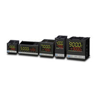
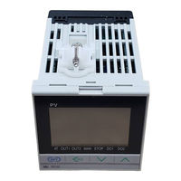
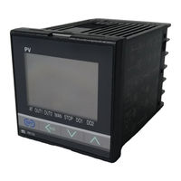
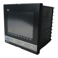
RB SERIES Digital Temperature Controller
Brand:
RKC INSTRUMENT
| Category:
Temperature Controller
| Size: 3 MB
Table of Contents
Safety Symbols
5
Table of Contents
8
1 Outline
13
Features
14
Input/Output and Function Blocks
15
Checking the Product
16
Model Code
17
Suffix Code
17
Quick Start Code (Initial Setting Code)
19
Parts Description
20
Display Units
22
Handling Procedure to Operation
25
2 Mounting
27
Mounting Cautions
28
Dimensions
29
Rb100
29
Rb400
29
Rb500
30
Rb700
30
Rb900
31
Procedures of Mounting and Removing
32
The Mounting Position of Mounting Bracket
32
Rb100
32
Rb400
32
Rb500
32
Rb700
32
Rb900
32
Mounting Procedures (Not Supplied)
33
Mounting Procedures (Waterproof/Dustproof Type)
34
Removal Procedures
35
3 Wiring
37
Wiring Cautions
38
Terminal Layout
41
Rb100
41
Rb400
41
Rb500
42
Rb700
42
Rb900
43
Isolations of Input and Output
43
Wiring of each Terminal
44
Power Supply
44
Output 1 (Out1)/Output 2 (OUT2)
45
Transmission Output (AO) [Optional]
46
Digital Output 1 to 4 (DO1 to DO4) [Optional]
47
Measured Input (Thermocouple/Rtd/Voltage/Current) [Universal Input]
48
Digital Input (DI1, DI2) [Optional]
49
Current Transformer (CT) Input [Optional]
49
Communication [Optional]
50
Handling of the Terminal Cover [Optional]
51
Mounting Procedures
51
Mounting Procedures (Not Supplied)
51
Removal Procedures
52
4 Basic Operation
53
Operation Menu
54
Changing Set Value
56
5 Setup Procedures Prior to Running the Instrument
58
Initial Setting
59
Check the Parameter Related to the Input
59
Check the Parameter Related to the Event
60
Check the Parameter Related to the Control Action
61
Operation Setting
62
Set the Control Set Value
62
Set the Event Set Value
63
Operation Start
64
Change from STOP to RUN
65
Tuning PID Parameters
66
Start the Autotuning (AT)
66
To Manually Adjust the PID Parameters
67
Changing Control Response with Fine Tuning
68
6 Operations of the Basic Functions
69
RUN/STOP Transfer
70
RUN/STOP Transfer by Front Key Operation
71
Performing Run/Stop Transfer in the "Run/Stop Setting" (Engineering Mode)
71
RUN/STOP Transfer by Digital Input (DI) [Optional]
73
Terminal Configuration
74
Autotuning (AT)
76
Caution for Using the Autotuning (AT)
76
Requirements for Autotuning (AT) Start
76
Requirements for Autotuning (AT) Cancellation
76
Autotuning (AT) Start/Stop Operation
77
Startup Tuning (ST)
79
Caution for Using the Startup Tuning (ST)
79
Requirements for Startup Tuning (ST) Start
80
Requirements for Startup Tuning (ST) Cancellation
80
Startup Tuning (ST) Setting
81
Fine Tuning
85
To Make Control Response Faster
85
Auto/Manual Transfer
88
Bumpless Function with Auto/Manual Transfer
88
Auto/Manual Transfer by Front Key Operation
89
Auto/Manual Transfer by Digital Input (DI)
90
Procedure for Setting the Manipulated Output Value (MV) in Manual Mode
91
Protecting Setting Data (Data Lock Function)
92
Set Lock Level
92
Setting Procedure Flowchart
92
Set Lock Level of Parameter Setting Mode
93
Locking All Data Which Can be Locked
94
Selecting the Parameter to Lock
96
Locking F21 to F91 Data
98
Display/No Display Setting of Mode Screens
100
Hiding the Parameters of the Monitor Display Mode
102
Hiding the Parameters of the Mode Switching Screen
103
Hiding the Parameters of the Parameter Setting Mode
105
Displaying Function Block 21 (F21) to Function Block 91 (F91) of the Engineering Mode
106
Interlock Release
107
Interlock Release by Front Key Operation
108
Interlock Release by Digital Input (DI)
109
7 Operating Additional Functions
111
SV Selection Function (Step SV Function)
112
Setting Procedure
112
SV Selection by Front Key Operation
113
SV Selection by Digital Input (DI)
114
Timer Function
115
Control Start (RUN) by Timer Function (Timer Function 1)
115
Control Stop (STOP) by Timer Function (Timer Function2)
117
Ramp/Soak Control (Timer Function 3, Timer Function 4)
119
Timer Setting
120
Transmission Output Function
122
Setting Procedure
122
Output Calibration
123
8 Parameter Description
125
Monitor Display Mode
126
Display Sequence
126
Monitor Item
127
SV Setting Mode
130
Display Sequence
130
Setting Item
131
Measured Value (Pv)/Manipulated Output Value (MV)
132
Mode Switching
133
Display Sequence
133
Parameter Setting Mode
136
Display Sequence
136
Parameter Setting Item
137
Data Range
149
Integral Time
150
Derivative Time
151
Output Limiter High [Heat-Side Output Limiter (High)
162
Output Limiter Low [Cool-Side Output Limiter (High)
162
Engineering Mode
167
Display Sequence
167
Function Block Structure in the Engineering Mode
175
Restricting Access to Engineering Mode
175
Precaution against Parameter Change
176
When Input Type (INP) Is Changed
176
When Transmission Output Type (Ao) Is Changed
177
When Event 1 Type (ES1) Is Changed
177
When Event 2 Type (ES2) Is Changed
177
When Event 4 Type (ES4) Is Changed
177
When Output Limiter High (Olh) Is Changed
178
When Output Limiter Low (Oll) Is Changed
178
When Decimal Point Position (Pgdp) Is Changed
178
When Input Scale High (PGSH) Is Changed
178
When Input Scale Low (PGSL) Is Changed
179
When Setting Limiter High (SLH) Is Changed
179
When Setting Limiter Low (SLL) Is Changed
179
When Communication Protocol (CMPS) Is Changed
179
When Timer Time Unit (TMU) Is Changed
179
Example of Automatic Conversion
180
Engineering Setting Item
181
Function Block 01 (F)
184
Sv Selection
185
Function Block 03 (F)
190
Function Block 04 (F)
192
Function Block 06 (F)
197
Proportional Band [Cool-Side
198
Function Block 07 (F)
201
Function Block 08 (F)
204
Minimum On/Off Time of Proportioning Cycle [Heat-Side
204
Minimum On/Off Time of Proportioning Cycle [Cool-Side
206
Function Block 09 (F)
208
Function Block 10 (F)
210
Manual Manipulated Output Value (MV)
210
Input Type
212
Function Block 21 (F)
212
Pv Flashing Display at Input Error
218
Function Block 23 (F)
219
DI Assignment
219
Function Block 30 (F)
220
Output Action at Stop Mode
220
Stop Display Selection
221
Function Block 33 (F)
222
Transmission Output Type
222
Event 1 Type
225
Event 2 Type
225
Event 1 Differential Gap
237
Event 2 Differential Gap
237
Event 1 Interlock
244
Event 2 Interlock
244
Function Block 45 (F)
246
Ct Ratio (Number of Turns)
246
Number of Hba Delay Times
247
Function Block 51 (F)
248
Derivative Action
252
Time Setting of Proportional Cycle Time [Cool-Side
253
Function Block 52 (F)
254
At Cycles
254
At Differential Gap Time
255
Communication Protocol
257
Function Block 60 (F)
257
Communication Speed
258
Data Bit Configuration
258
Interval Time
259
Function Block 70 (F)
260
Function Block 91 (F)
261
Rom Version Monitor
261
Error Display
264
Specifications
273
Pid Control
279
Operation Mode
284
General Specifications
290
Appendix
294
Removing the Internal Assembly
294
Replacing the Waterproof/Dustproof Rubber Packing
296
Current Transformer (CT) Dimensions
298
Shunt Resistor for Current Input
299
Advertisement
RKC INSTRUMENT RB400 Manual (9 pages)
Process/Temperature Controller
Brand:
RKC INSTRUMENT
| Category:
Temperature Controller
| Size: 0 MB
Table of Contents
Model Code
2
Specifications
3
Rb100/400/500/700/900
3
Rb700
4
Relay Contact Output
5
Quick Start Code
6
External Dimensions
7
Rear Terminals
8
RKC INSTRUMENT RB400 Communication Quick Manual (2 pages)
Digital Temperature Controller
Brand:
RKC INSTRUMENT
| Category:
Temperature Controller
| Size: 0 MB
Table of Contents
1. Connection to Host Computer
1
1.1 Communication Terminal Number and Signal Details
1
1.2 Wiring Method
1
2. Setting
1
Description of each Parameters (Engineering Mode F60)
1
3. Communication Requirements
1
RS-485 Send/Receive Timing (RKC Communication)
1
Fail-Safe
1
Modbus Data Processing Precautions
1
4. Communication Data List
1
Communication Data (Modbus)
2
Advertisement
RKC INSTRUMENT RB400 Installaiton Instructions (2 pages)
RB SERIES DIGITAL
Brand:
RKC INSTRUMENT
| Category:
Temperature Controller
| Size: 0 MB
Table of Contents
1. Mounting
1
1.1 Mounting Cautions
1
1.2 Dimensions
1
1.3 Procedures of Mounting and Removing
1
2. Wiring
1
2.1 Wiring Cautions
1
2.2 Terminal Configuration
2
3. Specifications
2
4. Model Code
2
Advertisement
Related Products
RKC INSTRUMENT RB100
RKC INSTRUMENT RB900
RKC INSTRUMENT RB700
RKC INSTRUMENT RB500
RKC INSTRUMENT RB Series
RKC INSTRUMENT REX-P96 Series
RKC INSTRUMENT REX-F9000
RKC INSTRUMENT REX-D700
RKC INSTRUMENT REX-D900
RKC INSTRUMENT REX-D400
RKC INSTRUMENT Categories
Controller
Temperature Controller
Media Converter
Measuring Instruments
Control Systems
More RKC INSTRUMENT Manuals
Login
Sign In
OR
Sign in with Facebook
Sign in with Google
Upload manual
Upload from disk
Upload from URL