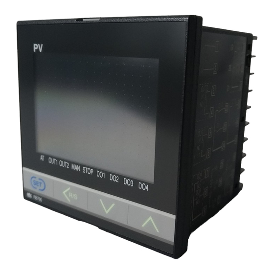
RKC INSTRUMENT RB900 Installaiton Instructions
Rb series digital
Hide thumbs
Also See for RB900:
- Communication quick manual (2 pages) ,
- Instruction manual (306 pages) ,
- Manual (9 pages)
Table of Contents
Advertisement
Quick Links
Download this manual
See also:
Instruction Manual
Digital Temperature Controller
Installation
RB series
RB series
Manual
(RB100/400/500/700/900)
(RB100/400/500/700/900)
All Rights Reserved, Copyright c 2009, RKC INSTRUMENT INC.
In order to achieve maximum performance and ensure proper operation of your new
instrument, carefully read all the instructions in this manual. Please place the manual in a
convenient location for easy reference. This Manual describes mounting, wiring, parts
descriptions, etc.
For detailed handling procedures and key operations, refer to separate RB series Instruction
Manual (IMR02C15-E□).
The manual can be downloaded from the official RKC website:
http://www.rkcinst.com/english/manual_load.htm.
■ Product Check
Installation Manual (this manual) .............................................1
Quick Operation Manual (IMR02C39-E□) .....................................1
Parameter List (IMR02C40-E□) .............................................1
Communication Quick Instruction Manual (IMR02C41-E□)
[For RB series with Communication] .........................................1
Mounting bracket (with screw) ...............................................2 *
Case rubber packing (Optional) [Waterproof/Dustproof] .........................1
* RB900 Waterproof/Dustproof type: 4
■ Optional (Sold separately)
Terminal cover .............................................................1
[RB100: KCA100-517 RB400/500/900: KFB400-58<1> RB700: KCA700-53]
Front cover ................................................................1
[RB100: KRB100-36 RB400/500: KRB400-36 RB900: KRB900-36]
■ Safety Precautions
!
WARNING
●An external protection device must be installed if failure of this instrument
could result in damage to the instrument, equipment or injury to personnel.
●All wiring must be completed before power is turned on to prevent electric
shock, fire or damage to instrument and equipment.
●This instrument must be used in accordance with the specifications to
prevent fire or damage to instrument and equipment.
●This instrument is not intended for use in locations subject to flammable
or explosive gases.
●Do not touch high-voltage connections such as power supply terminals,
etc. to avoid electric shock.
●RKC is not responsible if this instrument is repaired, modified or
disassembled by other than factory-approved personnel. Malfunction can
occur and warranty is void under these conditions.
CAUTION
● This product is intended for use with industrial machines, test and measuring quipment.
(It is not designed for use with medical equipment and nuclear energy.)
● This is a Class A instrument. In a domestic environment, this instrument may cause radio
interference, in which case the user may be required to take additional measures.
● This instrument is protected from electric shock by reinforced insulation. Provide reinforced
insulation between the wire for the input signal and the wires for instrument power supply,
source of power and loads.
● Be sure to provide an appropriate surge control circuit respectively for the following:
- If input/output or signal lines within the building are longer than 30 meters.
- If input/output or signal lines leave the building, regardless the length.
● This instrument is designed for installation in an enclosed instrumentation panel. All
high-voltage connections such as power supply terminals must be enclosed in the
instrumentation panel to avoid electric shock by operating personnel.
● All precautions described in this manual should be taken to avoid damage to the instrument
or equipment.
● All wiring must be in accordance with local codes and regulations.
● To prevent instrument damage or failure, protect the power line and the input/output lines
from high currents with a protection device such as fuse, circuit breaker, etc.
● Prevent metal fragments or lead wire scraps from falling inside instrument case to avoid
electric shock, fire or malfunction.
● Tighten each terminal screw to the specified torque found in the manual to avoid electric
shock, fire or malfunction.
● For proper operation of this instrument, provide adequate ventilation for heat dispensation.
● Do not connect wires to unused terminals as this will interfere with proper operation of the
instrument.
● Turn off the power supply before cleaning the instrument.
● Do not use a volatile solvent such as paint thinner to clean the instrument. Deformation
or discoloration will occur. Use a soft, dry cloth to remove stains from the instrument.
● To avoid damage to instrument display, do not rub with an abrasive material or push front
panel with a hard object.
● When high alarm with hold action/re-hold action is used for Event function, alarm does not
turn on while hold action is in operation. Take measures to prevent overheating which may
occur if the control device fails.
NOTICE
● This manual assumes that the reader has a fundamental knowledge of the principles of
electricity, process control, computer technology and communications.
● The figures, diagrams and numeric values used in this manual are only for purpose of
illustration.
● RKC is not responsible for any damage or injury that is caused as a result of using this
instrument, instrument failure or indirect damage.
● RKC is not responsible for any damage and/or injury resulting from the use of instruments
made by imitating this instrument.
● Periodic maintenance is required for safe and proper operation of this instrument. Some
components have a limited service life, or characteristics that change over time.
●
Every effort has been made to ensure accuracy of all information contained herein. RKC
makes no warranty expressed or implied, with respect to the accuracy of the
information. The information in this manual is subject to change without prior notice.
●
No portion of this document may be reprinted, modified, copied, transmitted, digitized,
stored, processed or retrieved through any mechanical, electronic, optical or other
means without prior written approval from RKC.
IMR02C38-E4
1. MOUNTING
!
WARNING
To prevent electric shock or instrument failure, always turn
off the power before mounting or removing the instrument.
1.1 Mounting Cautions
(1) This instrument is intended to be used under the following environmental conditions.
(IEC61010-1) [OVERVOLTAGE CATEGORY II, POLLUTION DEGREE 2]
(2) Use this instrument within the following environment conditions:
●
Allowable ambient temperature:
0 to 50
o
C
●
Allowable ambient humidity:
10 to 90 %RH
(Absolute humidity:
MAX. W. C 29.3 g/m
●
Installation environment conditions: Indoor use, Altitude up to 2000 m
(3) Avoid the following conditions when selecting the mounting location:
●
Rapid changes in ambient temperature which may cause condensation.
●
Corrosive or inflammable gases.
●
Direct vibration or shock to the mainframe.
●
Water, oil, chemicals, vapor or steam splashes.
●
Excessive dust, salt or iron particles.
●
Excessive induction noise, static electricity, magnetic fields or noise.
●
Direct air flow from an air conditioner.
●
Exposure to direct sunlight.
●
Excessive heat accumulation.
(4) Mount this instrument in the panel considering the following conditions:
●
Provide adequate ventilation space so that heat does not build up.
●
Ensure at least 50 mm space on top and bottom of the instrument for maintenance
and environmental reasons.
●
Do not mount this instrument directly above equipment that generates large amount of
heat (heaters, transformers, semi-conductor functional devices, large-wattage resistors.)
o
●
If the ambient temperature rises above 50
C, cool this instrument with a forced air fan,
cooler, etc. Cooled air should not blow directly on this instrument.
●
In order to improve safety and the immunity to withstand noise, mount this instrument as
far away as possible from high voltage equipment, power lines, and rotating machinery.
High voltage equipment: Do not mount within the same panel.
Power lines:
Separate at least 200 mm.
Rotating machinery:
Separate as far as possible.
o
●
The view angle of this controller is 30
to the upper side and the lower side from the
center of the display.
(5) If this instrument is permanently connected to equipment, it is important to include a
switch or circuit-breaker into the installation. This should be in close proximity to the
equipment and within easy reach of the operator. It should be marked as the
disconnecting device for the equipment.
1.2 Dimensions
RB100
RB700
(Unit: mm)
(Unit: mm)
48
*2
*1
1
7.9
63
79.1
RB400
(Unit: mm)
RB900
48
*2
(Unit: mm)
*1
1
7.9
60
70.1
*2
RB500
(Unit: mm)
Case rubber packing (optional)
*1
[Waterproof/Dustproof]
1
*1
*2
Terminal cover (optional)
7.9
60
[sold separately]
70.1
96
Panel thickness: 1 to 10 mm
(When mounting multiple RB series controllers
close together, the panel strength should be
checked to ensure proper support.)
RB100/700/900
*1
Individual mounting
Close horizontal mounting
25
A
D
L1
RB400
RB500
*1
Individual mounting
Individual mounting
+0.6
25 45
30
0
*2
Close horizontal mounting
Close horizontal mounting
+0.6
L1
0
dry air at 101.3 kPa)
3
L1 = 48×n - 3
L1 = 48×n - 3
n: Number of controllers (2 to 6)
n: Number of controllers (2 to 6)
1.3 Procedures of Mounting and Removing
■ Mounting procedures
1.
Prepare the panel cutout as specified in 1.2 Dimensions.
2.
Insert the instrument through the panel cutout.
3.
Insert the mounting bracket into the mounting groove of
the instrument.
4.
Push the mounting bracket forward until the bracket is firmly
secured to the panel. (Fig. 1)
5.
Only turn one full revolution after the screw touches the panel.
(Fig. 2)
6.
The other mounting bracket should be installed the same way described in 3. to 5.
The front of the instrument conforms to IP66 (NEMA4X) [Specify when ordering]
when mounted on the panel. For effective Waterproof/Dustproof, the gasket must be
securely placed between instrument and panel without any gap. If gasket is
damaged, please contact RKC sales office or the agent.
● The mounting position of the mounting bracket
RB100
RB400
*
72
*2
1
*1
7.9
60
81.7
If only two mounting brackets are used on the Waterproof/Dustproof type controller
as shown in the figure (marked*), sufficient Waterproof/Dustproof performance
cannot be obtained.
■ Removal procedures
1.
Turn the power OFF.
2.
Remove the wiring.
3.
Loosen the screw of the mounting bracket.
4.
Lift the latch of the mounting bracket (①), then pull the mounting
bracket (②), to remove it from the case. (Fig. 3)
The other mounting bracket should be removed in the same way
5.
as described in 3. and 4.
6.
Pull out the instrument from the mounting cutout while holding
the front panel frame of this instrument. (Fig. 4)
Use long-nose pliers to remove mounting brackets from the
instrument that is installed in a narrow place or installed
tightly in a vertical position.
2. WIRING
*2
A
B
C
L1
D
E
+0.6
+0.6
+0.6
+0.6
RB100
45
45
25
48×n3
45
0
0
0
0
To prevent electric shock or instrument failure, do not turn
+0.7
+0.7
+0.7
+0.7
RB700
68
68
30
72×n
68
0
0
0
0
on the power until all wiring is completed. Make sure that
+0.8
+0.8
+0.8
+0.8
RB900
92
92
30
96×n
92
0
0
0
0
the wiring is correct before applying power to the
n: Number of controllers (2 to 6)
instrument.
2.1 Wiring Cautions
*1
*1
To keep the instrument as waterproof
For thermocouple input, use the appropriate compensation wire.
●
+0.8
as possible, make sure that the panel
92
0
●
For RTD input, use low resistance lead wire with no difference in resistance between
surface has no burr or distortion where
the three lead wires.
the hole is to be cut out.
To avoid noise induction, keep input signal wire away from instrument power line, load
*2
Remove the case rubber packing.
lines and power lines of other electric equipment.
When the RB series is mounted
If there is electrical noise in the vicinity of the instrument that could affect operation, use
closely protection will be compromised
●
and they will not meet IP66 (NEMA4X)
a noise filter.
standards.
- Shorten the distance between the twisted power supply wire pitches to achieve the
*2
+0.8
most effective noise reduction.
92
0
- Always install the noise filter on a grounded panel. Minimize the wiring distance
between the noise filter output and the instrument power supply terminals to achieve
the most effective noise reduction.
- Do not connect fuses or switches to the noise filter output wiring as this will reduce the
effectiveness of the noise filter.
Allow approximately 5 seconds for contact output when the instrument is turned on. Use
●
a delay relay when the output line is used for an external interlock circuit.
●
Power supply wiring must be twisted and have a low voltage drop.
●
This instrument is not furnished with a power supply switch or fuse. If a fuse or power
Fig. 1
supply switch is required, install close to the instrument.
- Recommended fuse rating: Rated voltage 250 V, Rated current 1 A
For the current input specification, a shunt resistor of 250Ω ±0.02 % (Temperature
●
characteristics: ±10 ppm/
Fig. 2
between the input terminals.
For an instrument with 24 V power supply, supply power from a SELV circuit.
●
●
A suitable power supply should be considered in end-use equipment. The power supply
must be in compliance with a limited-energy circuits (maximum available current of 8 A).
●
Use the solderless terminal appropriate to the screw size.
Screw size:
Recommended tightening torque: 0.4 N・m (4 kgf・cm)
Applicable wire: Solid/twisted wire of 0.25 to 1.65 mm
Specified dimension: Refer to Fig. at the right
Specified solderless terminals:
RB500
RB700
RB900
●
Make sure that the any wiring such as solderless terminal is not in contact with the
adjoining terminals.
When tightening a screw of the instrument, make
sure to fit the screwdriver properly into the screw
head mounted tilted or flat as shown in the right
figure. Tightening the screw with excessive torque
*
may damage the screw thread.
If specified terminal lugs other than those in not recommended dimensions are
used, terminal screws may not be tightened. In such a case, bend each solderless
terminal lug in advance and then conduct wiring. If the terminal screw is forcibly
tightened, it may be damaged.
Up to two solderless terminal lugs can be connected to one terminal screw.
However, in this case, reinforced insulation cannot be used.
Caution for the terminal cover usage:
If each solderless terminal lug touches the terminal cover, remove each projection
(marked *A) from the terminal cover by manually bending it in front and in rear until
broken.
RB100
For isolated device input/output blocks, refer to the following:
Fig. 3
①
Commu-
②
nication
(RS-485)
Fig. 4
Panel
Digital
input
Pull out
DI1
DI2
Front panel frame
1
Outputs are isolated if output 1 (OUT1) or output 2 (OUT2) is "relay contact output" or "triac
trigger output." If both outputs are "relay contact output" or " triac trigger output," outputs are
not isolated.
2
Outputs of DO1/DO2 and DO3/DO4 are isolated.
DO1 and DO2 or DO3 and DO4 use the same common terminal (No. 9 for DO1/DO2, and
No. 21 for DO3/DO4) and are not isolated.
!
WARNING
Fuse type: Time-lag fuse
o
C, Specified voltage: 0.25 W or more) must be connected
φ5.5 MAX
M3×7 (with 5.8×5.8 square washer)
φ3.2 MIN
φ5.0
2
9.0 mm
5.6 mm
Manufactured by J.S.T MFG CO., LTD.
Circular terminal with isolation V1.25-MS3
(M3 screw, width 5.5 mm, hole diameter 3.2 mm)
Tilted terminal Flat terminal
Terminal cover
Terminal cover
(sold separately)
(sold separately) *
* The same type of the
*A
terminal cover for
RB900 can be used
on RB400/500.
RB900
Power supply
Isolated
Isolated
Isolated
Isolated
MCU
Non-isolated
1
Output1
Digital
(OUT1)
Measured input
2
output
Isolated
Isolated
Isolated
1
Output2
DO1
Non-isolated
(OUT2)
DO2
DO3
Loader
CT input
commu-
DO4
(CT1, CT2)
nication
Advertisement
Table of Contents

Related Manuals for RKC INSTRUMENT RB900


Summary of Contents for RKC INSTRUMENT RB900
- Page 1 +0.6 +0.6 +0.6 +0.6 RB100 48×n3 means without prior written approval from RKC. IMR02C38-E4 All Rights Reserved, Copyright c 2009, RKC INSTRUMENT INC. To prevent electric shock or instrument failure, do not turn +0.7 +0.7 +0.7 +0.7 RB700 72×n In order to achieve maximum performance and ensure proper operation of your new on the power until all wiring is completed.
- Page 2 -Input span to + Input span (Voltage/Current input) Additional function: Autotuning, Startup tuning, Fine tuning RB400: Approx. 185 g RB900: Approx. 250 g First order lag digital filter: 0 to 100 seconds (0: filter OFF) RB500: Approx. 190 g RB100...
Need help?
Do you have a question about the RB900 and is the answer not in the manual?
Questions and answers