Advertisement
Quick Links
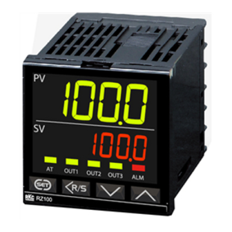
Temperature Controller
Instruction
RZ100/RZ400
Manual
All Rights Reserved, Copyright 2015, RKC INSTRUMENT INC.
Thank you for purchasing this RKC product. In order to achieve maximum performance and ensure
proper operation of the instrument, carefully read all the instructions in this manual. Please place
the manual in a convenient location for easy reference.
For detailed handling procedures and key operations, refer to separate
RZ100/RZ400/RS100/RS400 Instruction Manual (IMR02Y03-E).
The manual can be downloaded from the official RKC website:
http://www.rkcinst.com/english/manual_load.htm
!
WARNING
To prevent injury to persons, damage to the instrument and equipment,
a suitable external protection device shall be required.
All wiring must be completed before power is turned on to prevent
electric shock, fire or damage to the instrument and equipment.
This instrument must be used in accordance with the specifications to
prevent fire or damage to the instrument and equipment.
This instrument is not intended for use in locations subject to flammable
or explosive gases.
Do not touch high-voltage connections such as power supply terminals,
etc. to avoid electric shock.
RKC is not responsible if this instrument is repaired, modified or
disassembled by other than factory-approved personnel. Malfunction may
occur and warranty is void under these conditions.
CAUTION
This product is intended for use with industrial machines, test and measuring
equipment. (It is not designed for use with medical equipment and nuclear energy plant.)
This is a Class A instrument. In a domestic environment, this instrument may cause
radio interference, in which case the user may be required to take additional measures.
This instrument is protected from electric shock by reinforced insulation. Provide
reinforced insulation between the wire for the input signal and the wires for instrument
power supply, source of power and loads.
Be sure to provide an appropriate surge control circuit respectively for the following:
- If input/output or signal lines within the building are longer than 30 meters.
- If input/output or signal lines leave the building, regardless the length.
This instrument is designed for installation in an enclosed instrumentation panel. All
high-voltage connections such as power supply terminals must be enclosed in the
instrumentation panel to avoid electric shock to operating personnel.
1.3 Procedures of Mounting and Removing
Mounting procedures
1. Prepare the panel cutout as specified in
1.2 Dimensions.
2. Insert the instrument through the panel
cutout.
3. Insert the mounting bracket into the
mounting groove of the instrument. (Fig. 1)
4. Push the mounting bracket forward until
the bracket is firmly secured to the panel.
(Fig. 2)
5. Tighten the screw for the mounting
bracket with a Phillips screwdriver.
Do not overtighten the screw.
Recommended tightening torque:
0.15 Nm [1.5 kgfcm]
6. The other mounting bracket should be
installed in the same way as described in
3 to 5.
Removal procedures
1. Turn the power OFF.
2. Remove the wiring.
3. Loosen the screw of the mounting bracket.
4. Remove the mounting bracket by pulling it
up (Fig. 4 [1]) and forward (Fig. 4 [2]) while
holding the rear (Fig. 3).
Rear of mounting
bracket
5. The other mounting bracket(s) should be
removed in the same way as described
1
in 3 and 4.
6. Pull
out
the
instrument
from
the
mounting cutout while holding the front
panel frame of this instrument.
3. PARTS DESCRIPTION
Front Panel View
RZ400
RZ100
8888
PV
8888
PV
(1)
(1)
8888
SV
(2)
SV
8888
(3)
AT
OUT1
OUT2
OUT3
ALM
(2)
(3)
(4)
(5)
(6)
(7)
AT
OUT1
OUT2
OUT3
To avoid damage to the
instrument, never use a
sharp object to press keys.
(4)
(5)
(6)
Bottom View
RZ100
RZ400
(8)
5. MODEL CODE
Suffix code
- * /-
RZ100
RZ400
(1) (2) (3)
(4) (5) (6) (7) (8)
(9)
: These codes are used for Quick start code. If not specified, these codes are not shown
on the label.
(1) Output 1 (OUT1),
(7) Quick start code
N: Quick start code not specified
(2) Output 2 (OUT2)
1: Specify quick start code 1
N: None
2: Specify quick start code 1 and 2
M: Relay contact output
V: Voltage pulse output (0/12 V DC)
(8)
Control method [Quick start code 1]
7: Current output (0 to 20 mA DC)
No code: No specify quick start code
8: Current output (4 to 20 mA DC)
F: PID control with AT (Reverse action)
(3) Output 3 (OUT3)
D: PID control with AT (Direct action)
G: Heat/Cool PID control with AT
N: None
A: Heat/Cool PID control with AT
M: Relay contact output
(for Extruder [air cooling])
(4) Current transformer (CT) input
W: Heat/Cool PID control with AT
(optional)
(for Extruder [water cooling])
N: None
(9)
Measured input and Range
T: CTL-6-P-N 2 points
[Quick start code 1]
U: CTL-12-S56-10L-N 2 points
No code: No specify quick start code
(5) Communication (optional)
: Refer to Range Code Table
N: None
5: RS-485 (RKC communication)
6: RS-485 (Modbus)
(6) Waterproof/Dustproof (optional)
N: None
1: Waterproof/Dustproof (IP66)
If "N" or "1" is specified for (7), refer to a separate RZ100/RZ400/RS100/RS400
Instruction Manual (IMR02Y03-E) concerning the control action, input range,
output assignment and alarm type at the time of shipment.
All precautions described in this manual should be taken to avoid damage to the
instrument or equipment.
If the equipment is used in a manner not specified by the manufacturer, the protection
provided by the equipment may be impaired.
All wiring must be in accordance with local codes and regulations.
To prevent instrument damage as a result of failure, protect the power line and the
IMR02Y02-E1
input/output lines from high currents with a suitable overcurrent protection device
with adequate breaking capacity such as a fuse, circuit breaker, etc.
A malfunction in this product may occasionally make control operations impossible or
prevent alarm outputs, resulting in a possible hazard. Take appropriate measures in
the end use to prevent hazards in the event of malfunction.
Prevent metal fragments or lead wire scraps from falling inside instrument case to
avoid electric shock, fire or malfunction.
Tighten each terminal screw to the specified torque found in the manual to avoid
electric shock, fire or malfunction.
For proper operation of this instrument, provide adequate ventilation for heat dissipation.
Do not connect wires to unused terminals as this will interfere with proper operation
of the instrument.
Turn off the power supply before cleaning the instrument.
Do not use a volatile solvent such as paint thinner to clean the instrument. Deformation
or discoloration will occur. Use a soft, dry cloth to remove stains from the instrument.
To avoid damage to the instrument display, do not rub with an abrasive material or
push the front panel with a hard object.
NOTICE
This manual assumes that the reader has a fundamental knowledge of the principles
of electricity, process control, computer technology and communications.
The figures, diagrams and numeric values used in this manual are only for
explanation purpose.
RKC is not responsible for any damage or injury that is caused as a result of using
this instrument, instrument failure or indirect damage.
RKC is not responsible for any damage and/or injury resulting from the use of
instruments made by imitating this instrument.
Periodic maintenance is required for safe and proper operation of this instrument.
Some components have a limited service life, or characteristics that change over time.
Every effort has been made to ensure accuracy of all information contained herein.
RKC makes no warranty expressed or implied, with respect to the accuracy of the
information. The information in this manual is subject to change without prior notice.
No portion of this document may be reprinted, modified, copied, transmitted, digitized,
stored, processed or retrieved through any mechanical, electronic, optical or other
means without prior written approval from RKC.
Various symbols are used on the equipment, they have the following meaning.
: Alternating current
: Reinforced insulation
: Safety precaution
!
This symbol is used where the instruction manual needs to be consulted for the
safety of operator and equipment. Carefully read the cautions in this manual
before using the instrument.
2. WIRING
Fig. 1
WARNING
!
To prevent electric shock or instrument failure, do not turn on the power
until all wiring is completed. Make sure that the wiring is correct before
applying power to the instrument.
Fig. 2
2.1 Terminal Configuration
RZ100
RZ100
①
⑬
⑦
Power supply
②
⑭
⑧
Output 3 (OUT3)
③
⑮
⑨
Output 2 (OUT2)
④
⑩
⑯
⑤
⑪
⑰
Measured input
Output 1 (OUT1)
⑥
⑫
⑱
Communication (Optional)
Current transformer input (Optional)
Communication
Fig. 3
Power supply
(Optional)
AC
L
SG
13
1
100240 V
RS-485
T/R (A)
14
2
N
T/R (B)
15
Output 2 (OUT2)
Fig. 4
Voltage pulse
Current
Relay contact
Current
transformer input
OUT2
(Optional)
3
3
2
OUT2
NO
16
4
4
CT2
17
CT1
Output 1 (OUT1)
18
Voltage pulse
COM
Relay contact
Current
OUT1
5
5
To prevent malfunctioning, do not
OUT1
NO
connect wires to unused terminals
The dotted box diagram describes
6
6
the output state of the instrument.
(1) Measured value (PV)
Displays Measured value (PV) or various parameter
display
[Green]
symbols.
(2) Set value (SV) display
Displays Set value (SV) or various parameter set
[Orange]
values.
(3) AT lamp
[Green] Flashes when Autotuning (AT) is activated.
(After AT is completed: AT lamp will go out)
Lights during Startup tuning (ST) execution.
(After ST is completed: AT lamp will go out)
OUT1 lamp
[Green] Lights when Output 1 (OUT1)
OUT2 lamp
[Green] Lights when Output 2 (OUT2)
OUT3 lamp
[Green] Lights when Output 3 (OUT3)
ALM lamp
[Red] Lights when Alarm 1, Alarm 2, Heater break alarm 1
or Heater break alarm 2 is turned on.
(4) Set (SET) key
Used for calling up parameters and set value
ALM
registration.
(5) Shift key
Shifts digits when settings are changed.
Used to switch RUN/STOP and modes.
(6) Down key
Decreases numerals.
(7) Up key
Increases numerals.
(8) Loader communication
Setting and monitoring on a personal computer (PC)
connector
is possible if the controller is connected with our cable
to a PC via our USB communication converter COM-K
(7)
(sold separately)*. Our communication software**
must be installed on the PC.
* For the COM-K, refer to the official RKC website.
** Only available as a download from the official RKC
website.
http://www.rkcinst.com
1
Control output (heat-side/cool-side), Alarm output and Heater break alarm output
can be assigned to Outputs 1, 2, and 3 (OUT1, 2, and 3).
Output assignment can be made in the Initial setting mode. For details, refer to
separate RZ100/RZ400/RS100/RS400 Instruction Manual (IMR02Y03-E).
2
Lamp indication becomes as follows for current output.
For an output of less than 0 %:
For an output of more than 100 %:
For an output of more than 0 % but less than 100 %: Dimly lit.
Quick start code 2 (Initial setting code)
- - -
(1) (2) (3) (4) (5) (6) (7)
(1) Alarm 1 type, (2) Alarm 2 type
N: None
T: Deviation high/low with re-hold action
A: Deviation high
U: Band
B: Deviation low
(High/low individual setting)
C: Deviation high/low
V: SV high
D: Band
W: SV low
E: Deviation high with hold action
X: Deviation high/low
F: Deviation low with hold action
(High/low individual setting)
G: Deviation high/low with hold action
Y: Deviation high/low with hold action
H: Process high
(High/low individual setting)
J: Process low
Z: Deviation high/low with re-hold action
K: Process high with hold action
(High/low individual setting)
L: Process low with hold action
2: Control loop break alarm (LBA)
Q: Deviation high with re-hold action
4: Monitor during RUN
R: Deviation low with re-hold action
(3) Control output assignment
1: PID control:
Output 1 (OUT1)
Heat/Cool PID control: Heat-side output: Output 1 (OUT1)
Cool-side output: Output 2 (OUT2)
2: PID control:
Output 2 (OUT2)
Heat/Cool PID control: Heat-side output: Output 2 (OUT2)
Cool-side output: Output 1 (OUT1)
b
3
: Heat-side output: Output 1 (OUT1)
Cool-side output: Output 3 (OUT3)
b
4
: Heat-side output: Output 2 (OUT2)
Cool-side output: Output 3 (OUT3)
b
Can be specified only for Heat/Cool PID control.
(4) Output assignment of Alarm 1, (5) Output assignment of Alarm 2
(Cannot be specified if the output terminal is already specified for control output.)
N: No assignment
2: Output 2 (OUT2)
1: Output 1 (OUT1)
3: Output 3 (OUT3)
(6) Output assignment of Heater break alarm 1,
(7) Output assignment of Heater break alarm 2
(Cannot be specified if the output terminal is already specified for control output.)
N: No assignment
2: Output 2 (OUT2)
1: Output 1 (OUT1)
3: Output 3 (OUT3)
1. MOUNTING
!
To prevent electric shock or instrument failure, always turn off the power
before mounting or removing the instrument.
1.1 Mounting Cautions
(1) This instrument is intended to be used under the following environmental conditions.
(IEC61010-1) [OVERVOLTAGE CATEGORY II, POLLUTION DEGREE 2]
(2) Use this instrument within the following environment conditions:
Allowable ambient temperature:
Allowable ambient humidity:
Installation environment conditions: Indoor use
(3) Avoid the following conditions when selecting the mounting location:
Rapid changes in ambient temperature which may cause condensation.
Corrosive or inflammable gases.
Direct vibration or shock to the mainframe.
Water, oil, chemicals, vapor or steam splashes.
Excessive dust, salt or iron particles.
Excessive induction noise, static electricity, magnetic fields or noise.
Direct air flow from an air conditioner.
Exposure to direct sunlight.
Excessive heat accumulation.
(4) Mount this instrument in the panel considering the following conditions:
Ensure at least 50 mm space on top and bottom of the instrument for maintenance and
operating environment.
Do not mount this instrument directly above equipment that generates large amount of heat
(heaters, transformers, semi-conductor functional devices, large-wattage resistors).
If the ambient temperature rises above 55 C, cool this instrument with a forced air fan, cooler,
etc. Cooled air should not blow directly on this instrument.
In order to improve safety and the immunity to withstand noise, mount this instrument as far
away as possible from high voltage equipment, power lines, and rotating machinery.
High voltage equipment: Do not mount within the same panel.
Power lines:
Separate at least 200 mm.
Rotating machinery:
Separate as far as possible.
For correct functioning mount this instrument in a horizontal position.
(5) In case this instrument is connected to a supply by means of a permanent
connection, a switch or circuit-breaker shall be included in the installation. This shall
be in close proximity to the equipment and within easy reach of the operator. It shall
be marked as the disconnecting device for the equipment.
RZ400
Power supply
Output 2 (OUT2)
Output 1 (OUT1)
Unused
Output 3 (OUT3)
Measured input
Power supply
Unused
AC
L
1
100240 V
2
N
Output 2 (OUT2)
Voltage pulse
Relay contact
Current
Output 3 (OUT3)
OUT2
3
3
Relay contact
OUT2
NO
4
OUT3
4
8
NO
Output 1 (OUT1)
9
Voltage pulse
Relay contact
Current
Measured input
OUT1
5
5
TC input
RTD input
OUT1
NO
10
A
6
6
RTD
11
11
B
TC
2.2 Wiring Cautions
12
12
B
For thermocouple input, use the appropriate compensation wire.
For RTD input, use low resistance lead wire with no difference in resistance between
NO: Normally open
the three lead wires.
To avoid noise induction, keep input signal wire away from instrument power line, load
lines and power lines of other electric equipment.
If there is electrical noise in the vicinity of the instrument that could affect operation,
use a noise filter.
4. SPECIFICATIONS
Measured input
Number of input:
1 point
TC input:
K, J, T, S, R, E, B, N (JIS C1602-1995), PLII (NBS),
W5Re/W26Re (ASTM-E988-96), U, L (DIN43710-1985)
RTD input:
Pt100 (JIS C1604-1997), JPt100 (JIS C1604-1997, Pt100 of JIS
C1604-1981)
Input accuracy:
Input type
1
2
is turned on.
1
2
K, J, T, E,
is turned on.
PLII, U, L
1
is turned on.
R, S, N,
W5Re/W26Re
B
Pt100, JPt100
*1: Accuracy is not guaranteed for less than 100 C
*2: Accuracy is not guaranteed for less than 400 C for input type R, S,
W5Re/W26Re and B.
Sampling cycle:
0.25 seconds
Influence of signal source resistance:
Approx. 0.2 V/ (TC input)
Influence of input lead:
Approx. 0.02 %/ of span (RTD input)
Approx. 800 A (RTD input)
Measured current:
Action at input break:
Upscale (TC input and RTD input)
Action at input short circuit:
Downscale (RTD input)
1999 to 9999 C [F] or 199.9 to 999.9 C [F]
PV bias:
PV digital filter (First order lag digital filter):
0 to 100 seconds (0: Filter OFF)
Current transformer (CT) input
Extinguished
Number of input:
2 points (maximum)
Lit
Input range:
0.0 to 30.0 A (CTL-6-P-N)
0.0 to 100.0 A (CTL-12-S56-10-N)
Sampling cycle:
0.5 seconds
Range Code Table
TC input
Type Code
Range
Type Code
0 to 200 C
K
K01
J
0 to 400 C
K02
0 to 600 C
K03
0 to 800 C
K04
T
0 to 1000 C
K05
0 to 1200 C
K06
0 to 1372 C
K07
0.0 to 400.0 C
K09
0.0 to 800.0 C
K10
0 to 100 C
K13
R
0 to 300 C
K14
0 to 450 C
K17
0 to 500 C
K20
200 to +1372 C
K41
S
K43 199.9 to +400.0 C
a
0 to 800 F
KA1
B
0 to 1600 F
KA2
0 to 2502 F
KA3
E
a
Can be specified only for Alarm 2.
KC8 100.0 to 752.0 F
0 to 200 C
J
J01
N
0 to 400 C
J02
W5Re/
0 to 600 C
W26Re
J03
0 to 800 C
J04
0 to 1000 C
J05
PLII
0 to 1200 C
J06
J07 199.9 to +300.0 C
0 to 450 C
J10
0 to 800 F
JA1
0 to 1600 F
JA2
U
0 to 2192 F
JA3
L
0 to 400 F
JA6
1.2 Dimensions
RZ100
タイプ
WARNING
(Unit: mm)
10 to 55 C
5 to 95 %RH
3
(Absolute humidity: MAX. W. C 29 g/m
dry air at 101.3 kPa)
Altitude up to 2000 m
Short-term temporary overvoltage: 1440 V
タ
RZ400
Long-term temporary overvoltage: 490 V
(Unit: mm)
Panel thickness: 1 to 10 mm (When mounting multiple RZ100/400 controllers close together,
the panel strength should be checked to ensure proper support.)
*1 Gasket (optional)
*2 Terminal cover (optional) [sold separately]
*3 To keep the instrument as waterproof as possible, make sure that the panel surface has no
burr or distortion where the hole is to be cut out.
*4 Remove the gasket. When the RZ100/400 is mounted closely protection will be compromised
and they will not meet IP66 standards.
Shorten the distance between the twisted power supply wire pitches to achieve
RZ400
the most effective noise reduction.
①
⑬
Always install the noise filter on a grounded panel. Minimize the wiring distance
Communication
②
⑭
between the noise filter output and the instrument power supply terminals to achieve
(Optional)
③
⑮
the most effective noise reduction.
④
⑯
Do not connect fuses or switches to the noise filter output wiring as this will reduce
⑤
⑰
the effectiveness of the noise filter.
⑥
⑱
Allow approximately 5 seconds for contact output when the instrument is turned on. Use
Unused
⑦
⑲
a delay relay when the output line is used for an external interlock circuit.
⑧
⑳
Power supply wiring must be twisted and have a low voltage drop.
⑨
㉑
This instrument is not provided with an overcurrent protection device (fuse). If a fuse
⑩
㉒
Current transformer input
is required for safety, install close to the instrument.
⑪
㉓
(Optional)
Fuse type:
⑫
㉔
Fuse rating: Rated voltage 250 V
Communication
Use the solderless terminal appropriate to the screw size.
Output 3 (OUT3)
(Optional)
Screw size:
Recommended tightening torque: 0.4 Nm [4 kgfcm]
Relay contact
SG
13
Applicable wire:
OUT3
RS-485
8
Specified dimension: Refer to Fig. at the right
T/R (A)
14
Specified solderless terminal:
NO
9
T/R (B)
15
Make sure that during field wiring parts of conductors cannot come into contact with
Current
adjacent conductive parts.
Measured input
transformer input
If solderless terminal lugs other than the recommended dimensions are used,
TC input
RTD input
(Optional)
terminal screws may not be tightened. In that case, bend each solderless
10
A
terminal lug before wiring. If the terminal screw is forcibly tightened, it may be
22
RTD
damaged.
CT2
11
B
11
Up to two solderless terminal lugs can be connected to one terminal screw.
23
TC
However, reinforced insulation cannot be used.
CT1
12
12
B
24
For isolated device input/output blocks, refer to the following:
COM
NO: Normally open
To prevent malfunctioning, do not
connect wires to unused terminals
Isolated
The dotted box diagram describes
the output state of the instrument.
Isolated
Commu-
nication
(RS-485)
* Outputs are isolated if OUT1 or OUT2 is "relay contact output." If both outputs are
not "relay contact output," outputs are not isolated.
Output
Relay contact output (1) [OUT1, 2 and 3 of RZ100: Control output, OUT3 of RZ400: Control output]:
Contact type:
Contact rating (Resistive load): 250 V AC 3 A, 30 V DC 1 A
Electrical life:
Mechanical life:
Relay contact output (2) [OUT1 and 2 of RZ400: Control output]:
Contact type:
Contact rating (Resistive load): 250 V AC 3 A, 30 V DC 1 A
Input range
Accuracy
Less than 100 C
(2.0 C 1 digit)
Electrical life:
100 C or more,
(1.0 C 1 digit)
Mechanical life:
Less than 500 C
Relay contact output (3) [RZ100 and RZ400: Alarm output (including HBA output)]:
*1
500 C or more
(0.2 % of Reading 1 digit)
Contact type:
Less than 0 C
(4 C 1 digit)
Contact rating (Resistive load): 250 V AC 1 A, 30 V DC 0.5 A
0 C or more,
(2 C 1 digit)
Electrical life:
Less than 1000 C
Mechanical life:
*2
1000 C or more
(0.2 % of Reading 1 digit)
Voltage pulse output:
Less than 400 C
(70 C 1 digit)
Output voltage:
400 C or more
(2 C 1 digit)
*2
Allowable load resistance: 500 or more
Less than 200 C
(0.4 C 1 digit)
200 C or more
(0.2 % of Reading 1 digit)
Current output:
Output current:
Output range:
Allowable load resistance: 500 or less
Communication
Interface:
Protocol:
General specifications
Power supply voltage:
Power consumption:
Rush current:
Memory backup:
Weight:
RTD input
Range
Type Code
Range
0 to 300 F
Pt100 D01 199.9 to 649.0 C
Connect the controller, COM-K, and personal computer using a USB cable and a loader
JA7
communication cable. Make sure the connectors are oriented correctly when connecting.
328 to 2192 F
D02 199.9 to 200.0 C
JB9
JC8 199.9 to 550.0 F
D03 100.0 to 50.0 C
RZ100
T01 199.9 to +400.0 C
D04 100.0 to 100.0 C
T02 199.9 to +100.0 C
D05 100.0 to 200.0 C
T03 100.0 to +200.0 C
0.0 to 50.0 C
D06
0.0 to 350.0 C
0.0 to 100.0 C
T04
D07
T05 199.9 to +300.0 C
0.0 to 200.0 C
D08
0.0 to 400.0 C
0.0 to 300.0 C
T06
D09
0 to 1600 C
0.0 to 500.0 C
R01
D10
0 to 1769 C
DA1 199.9 to 999.9 F
R02
Connect to loader
0 to 1350 C
DA3 199.9 to 200.0 F
R04
communication
0 to 3200 F
DA4 199.9 to 100.0 F
RA1
connector of the
0 to 1600 C
DA5 199.9 to 300.0 F
S01
controller
0 to 1769 C
0.0 to 100.0 F
S02
DA6
400 to 1800 C
0.0 to 400.0 F
B01
DA8
0 to 1820 C
0.0 to 500.0 F
B02
DA9
0 to 800 C
DB2 199.9 to 900.0 F
E01
0 to 1000 C
JPt100 P01 199.9 to 649.0 C
E02
0 to 1200 C
P02 199.9 to 200.0 C
N01
0 to 2000 C
P04 100.0 to 100.0 C
W01
0 to 2320 C
P05 100.0 to 200.0 C
W02
0 to 4000 F
0.0 to 50.0 C
WA1
P06
0 to 1300 C
0.0 to 100.0 C
A01
P07
0 to 1390 C
0.0 to 200.0 C
A02
P08
Communication settings on the computer
0 to 1200 C
0.0 to 300.0 C
A03
P09
(The following values are all fixed)
0 to 2400 F
0.0 to 500.0 C
AA1
P10
0 to 2534 F
Communication speed: 38400 bps
AA2
U01 199.9 to +600.0 C
Start bit: 1
0 to 400 C
L01
Data bit: 8
Parity bit: Without
Stop bit: 1
Communication port of host computer
USB port: Based on USB Ver. 2.0
The Loader port is only for parameter setup. Not used for data logging
during operation.
To use the loader communication, power on RZ100/400.
Loader communication can be used on a RZ100/400 even when the
Communication function (optional) is not installed.
The loader communication corresponds to the RKC communication protocol
"Based on ANSI X3.28-1976 subcategories 2.5 and A4."
*3
Individual mounting
0.6
25
45
0
48
*2
Close horizontal
0.6
*4
mounting
L1
0
*1
1
7.9
63
L1 = 48 n 3
L1 = 48 × n 3
79.1
n = 取付台数 (2 ~6)
n: Number of controllers (2 to 6)
*3
Individual mounting
0.6
25
45
0
48
*2
Close horizontal
*4
0.6
mounting
L1
0
1
*1
7.9
60
L1 = 48 n 3
L1 = 48 × n 3
70.1
n: Number of controllers (2 to 6)
n = 取付台数 (2 ~ 6)
Time-lag fuse
Rated current: 1 A
5.9 MAX
M3×7 (with 5.8×5.8 square washer)
3.2 MIN
2
Solid/twisted wire of 0.25 to 1.65 mm
Manufactured by J.S.T MFG CO., LTD.
5.6 mm
Circular terminal with isolation V1.25MS3
Power supply
Isolated
Isolated
Isolated
MCU
Non-isolated
Output 1*
Measured input
Isolated
Isolated
(OUT1)
Output 3
Non-isolated
非絶縁
Output 2*
(OUT3)
(OUT2)
Loader
Current
commu-
transformer input
nication
(CT1, CT2)
1a contact
100,000 times or more (Rated load)
20 million times or more (Switching: 300 times/min)
1a contact
300,000 times or more (Rated load)
50 million times or more (Switching: 180 times/min)
1a contact
150,000 times or more (Rated load)
20 million times or more (Switching: 300 times/min)
0/12 V DC (Rated) ON voltage: 10 to 13 V
OFF voltage: 0.5 V or less
4 to 20 mA DC, 0 to 20 mA DC
3.2 to 20.8 mA DC, 0 to 21 mA DC
Based on RS-485, EIA standard
RKC communication (ANSI X3.28-1976 subcategories 2.5 and A4)
Modbus-RTU
85 to 264 V AC [Including power supply voltage variation]
(Rated: 100 to 240 V AC), 50/60 Hz
RZ100: 5.1 VA max. (at 100 V AC)
7.6 VA max. (at 240 V AC)
RZ400: 5.9 VA max. (at 100 V AC)
8.4 VA max. (at 240 V AC)
5.6 A or less (at 100 V AC)
13.3 A or less (at 240 V AC)
Backed up by non-volatile memory
Number of writing:
Approx. 1,000,000 times
Data storage period:
Approx. 10 years
RZ100: Approx. 115 g, RZ400: Approx. 165 g
How to connect the controller to a PC
via loader communication port
Loader communication
connector
USB
Connect to
communication
loader
Bottom View
converter
communication
COM-K
connector
Loader communication
cable 1.5 m (W-BV-01)
[COM-K optional]
Connect to USB
connector
Connect to
USB cable 1 m
USB port of
(COM-K accessory)
a personal
computer
Do not unplug the USB cable while the
power to the instrument is ON.
The device address for loader
communication is fixed at "0."
The setting of the device address is
disregarded.
Communication tool PROTEM2
Software operation environment:
Windows Vista, 7, 8 or 8.1
Advertisement

Related Manuals for RKC INSTRUMENT RZ100


Summary of Contents for RKC INSTRUMENT RZ100
- Page 1 (1) Measured value (PV) Displays Measured value (PV) or various parameter display [Green] symbols. Relay contact output (1) [OUT1, 2 and 3 of RZ100: Control output, OUT3 of RZ400: Control output]: Measured input Front Panel View Contact type: 1a contact...
- Page 2 0 to 9999 (10000) hours Heat-side output: Output 2 (OUT2) energize/de-energize when 1000: TC input S Cool-side output: Output 1 (OUT1) Refer to a separate RZ100/RZ400/RS100/RS400 assigned to alarm Alarm Type List 0 0 0 3: Heat-side output: Output 1 (OUT1) Instruction Manual (IMR02Y03-E) for the...
Need help?
Do you have a question about the RZ100 and is the answer not in the manual?
Questions and answers