
Subscribe to Our Youtube Channel
Related Manuals for HIKVISION DS-8104


Summary of Contents for HIKVISION DS-8104
- Page 1 Thank you for purchasing our product. Please read this User’s Manual before using the product. Change without Notice 4 / 8 CH DVR User’s Manual...
- Page 2 CAUTION Please read this user manual carefully to ensure that you can use the device correctly and safely We do not warrant all the content is correct. The contents of this manual are subject to change without notice This device should be operated only from the type of power source indicated on the marking label. The voltage of the power must be verified before using.
- Page 3 1.1 Main Features Real-time surveillance • High resolution VGA output (Default) • • 2 way audio 3G Mobile surveillance(iPhone/ iPad/ Android/ Windows Mobile/ BlackBerry/ Symbian) • Compression • With latest H.264 video compression, better video quality and lower compression rate. Storage •...
-
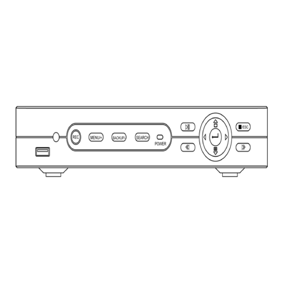
Page 4: Front Panel Instructions
1.2 Front Panel Instructions Notice: The pictures are only for reference; please make the object as the standard. 1. The Front Panel interface for 4/8ch DVR is shown as below: Fig 2.5 Front Panel for 4/8-ch DVR Name Description 1. Record manually Search 1. - Page 5 1.3 Rear Panel Instructions 1.3.1 Rear Panel Interface The rear Panel interface for 4-ch is shown as Fig 2.8: Fig 2.8 Rear Panel for 4-ch Name Description Video out Connect to monitor Audio out Audio output, connect to the sound box Connect to speed dome Connect to keyboard ALARM IN...
-
Page 6: Remote Controller (Optional)
1.4 Remote Controller (Optional) It uses two AAA size batteries and works after loading batteries as following: Step1: Open the battery cover of the Remote Controller Step2: Place batteries. Please take care the poles (+ and -) Step3: Replace the battery cover Notice: Frequently defect checking as following 1. -
Page 7: Use Mouse
1.5.2 Use Mouse The structure of the main menu is shown in Fig 2.11 Remote Controller. In live: Double-click left button on one camera to be full screen display. Double-click again to return to the previous screen display. Click right button to show the control bar at the bottom of the screen as Fig 2.11 Remote Controller. Here are all control and setup. Click right mouse again to hide the control bar. -
Page 8: Basic Function Instruction
Basic Function Instruction 2.1 Power On/Off Before you power on the unit, please make sure all the connection is good. 2.1.1 Power on Step1: connect with the source power; switch on the power button near the power port in the rear panel Step2: the device will be loaded, and the power indicator will display blue Step3: before start, a WIZARD dialogue box will be pop-up (refer to below picture) and show some information about time zone and time setup. -
Page 9: Live Preview
2.3 Live preview Fig 3-2 live preview interface The explanation of symbol in the live preview interface: symbol meaning symbol meaning Green Manual record or time record Alarm record Yellow Motion detection record Blue Schedule record 2.3.1 Live playback Click Play button to playback the record. -
Page 10: Main Menu Setup Guide
Main menu setup guide Click right mouse or press ESC button on the front panel, the control bar will display on the screen, refer to Fig 4-1: Full channel switch, camera 1 ~ 4 or camera 1 ~ 8 ① Single Full channel ②... -
Page 11: Basic Configuration
3.1 Basic configuration Basic configuration includes three sub menus: system、date& time and DST. 3.1.1 System Step1: enter into system configuration basic configuration system; refer to Fig 4-3: Fig 4-3 basic configuration-basic Step2: in this interface user can setup the device name, device ID, video format, max network users, VGA resolution and language. The definitions for every parameters display as below: Device name: the name of the device. -
Page 12: Live Configuration
3.1.3 DST Step1: enter into system configuration basic configuration DST; refer to Fig 4-5: Fig 4-5 basic configuration-DST Step2: in this interface, enable daylight saving time, time offset, mode, start & end month/week/date, etc. Step3: click “default” button to resort default setting; click “apply” button to save the setting; click “exit” button to exit current interface. 3.2 Live configuration Live configuration includes four submenus: live, host monitor, SPOT and mask. - Page 13 3.2.2 SPOT (Not available) Step1: enter into system configuration live configuration SPOT; refer to Fig 4-9: Fig 4-9 live configuration-SPOT Step2: select split mode: 1×1and channel Step3: dwell time: the time interval for a certain dwell picture display switching to next dwell picture display Step4: selected the split mode, then setup current picture group.
-
Page 14: Record Configuration
Live image mask area 3.3 Record configuration Record configuration includes five sub menus: enable, record bit rate, time, recycle record and stamp. 3.3.1 Enable Step1: enter into system configuration record configuration enable; refer to Fig 4-11: Fig 4-11 record configuration-enable Step2: tick off record, audio and record time Step3: user can setup all channels with same parameters, tick off “all”, then to do relevant setup. -
Page 15: Record Stream
3.3.2 Record stream Step1: enter into system configuration record configuration record bit rate; refer to Fig 4-10: Fig 4-10 record configuration-record bit rate Step2: setup rate, resolution, quality, encode and max bit stream Step3: user can setup all channels with same parameters, tick off “All”, then to do relevant setup. Step4: click “default”... -
Page 16: Recycle Record
3.3.4 Stamp Stamp:User can overlap the channel name and time stamp on video. Step1: enter into system configuration record configuration stamp; refer to Fig 4-13: Fig 4-13 record configuration-stamp Step2: tick off camera name, time stamp; click Set button, user can use cursor to drag the camera name and time stamp in random positions, refer to below Figures: Before drag after drag... - Page 17 3.4.1 Schedule The volume means the seven days of a week from Monday to Sunday, the row means 24 hours of a day. Click the grid to do relevant setup. Blue means checked area, gray means unchecked area. Step1: enter into system configuration schedule configuration schedule; refer to Fig 4-14: Fig 4-14 schedule configuration-schedule Step2: select channel, double-click and a dialog box will pop-up as Fig 4-15, user can edit week schedule: Fig 4-15 schedule-week schedule...
-
Page 18: Alarm Configuration
Step2: the setup steps of motion are familiar with schedule; user can refer to 4.4.1 Schedule for details. Note: the default schedule of motion detection is full-selected, that is, the color of schedule setting interface is blue. 3.4.3 Sensor Step1: enter into system configuration schedule configuration alarm; refer to Fig 4-17: Step2: the setup steps of alarm are familiar with schedule;... - Page 19 Step2: select hold time, click Trigger button, and a dialog box will pop-up as Fig 4-20: Fig 4-20 alarm handling-trigger Step3: tick off Buzzer, there will be triggered buzzer alarm out; Full screen alarm: when triggered alarm, there will pop up full screen alarm; To alarm out: tick off the channel, there will be triggered alarm out in the designated channel.
- Page 20 Fig 4-22 alarm configuration-motion Step2: enable motion alarm, set alarm hold time which means time interval between two adjacent detective motions. If there is other motion detected during the interval period which is considered continuous movement; otherwise, it will be considered that those two adjacent detective motions are two different motion events.
-
Page 21: Video Loss
3.5.3 Video loss Step1: enter into system configuration alarm configuration video loss; refer to Fig 4-25: Fig 4-25 alarm configuration-video loss Step2: the setup steps of video loss trigger are familiar with alarm handling; user can refer to Chapter 4.5.1 Sensor alarm handling for more details. -
Page 22: Network Configuration
Step3: user can setup all channels with same parameters, tick off “all”, then to do relevant setup. Step4: click “default” button to resort default setting; click “apply” button to save the setting; click “exit” button to exit current interface. ② Schedule Step1: enter into system configuration schedule;... -
Page 23: Network Stream
Definitions and descriptions of network configuration: Parameter Meaning HTTP port The port number of accessing IE browser. The default port is 80 Server port The port number of data. The default port is 6036 Static IP IP address The IP address of the server Subnet mask The subnet mask of the server Gateway... - Page 24 3.6.3 Email Step1: enter into system configuration network configuration email; refer to Fig 4-31: Fig 4-31 network configuration-email SMTP Server/Port: the name and port number of SMTP server. If your SMTP server support the secure connection (SSL), like gmail, please set the “Port” to 465 and check “SSL Check”...
-
Page 25: User Management Configuration
3.7 User management configuration Step1: enter into system configuration user management configuration; refer to Fig 4-33: Fig 4-33 user management configuration Step2: click Add button, a dialog box will pop-up as Fig 4-34: Fig 4-34 add-general General: Input user name, password; select user type: normal and advance, input the MAC address of the PC; click OK button, this user ①... - Page 26 Step2: tick off Enable, setup the value of address, baud rate and protocol according to the settings of the speed dome. Step3: user can setup all channels with same parameters, tick off “all”, then to do relevant setup. Step4: click “default” button to resort default setting; click “apply” button to save the setting; click “exit” button to exit current interface. Definitions and descriptions of network stream: Parameter Meaning...
- Page 27 b. user can control the dome rotates up, up left, down, right down, left , left down, right and up right and stop rotating; adjust the rotate speed and the value of zoom, focus and iris of the dome; c. select the serial number of the preset point, set the preset name. Click Save button to save the settings, click icon to hide the tool bar, right-key can remerge it;...
-
Page 28: Record Search & Playback And Backup
Record search & playback and backup Search configuration includes three submenus: time search, event search and file manager. 4.1 Time search Step1: enter into Search configuration time search; refer to Fig 5-1: Fig 5-1 Search configuration-time search Step2: select channel, screen display mode, the highlight date in the calendar means have record data Step3: select a date, press Search button, click the time grid to set the play start time or input play record time manually. -
Page 29: File Manager
4.3 File manager Step1: enter into Search configuration file manager; refer to Fig 5-3: Fig 5-3 Search configuration-file manager Step2: click Search button, the searched files will be displayed in the file list box, user can select date, channels accordingly. ①... -
Page 30: Manage Dvr
Step4: in the backup information interface, user can check the relevant information of backup files, storage type, save file type, etc. click Apply button to starting backup. Note: when the monitor resolution is VGA800*600, the file manager interface will appear a hide button, click this button, the whole interface can be expanded. -
Page 31: Network Information
5.1.4 Network information In this interface, user can check relevant parameters of network; refer to Fig 6-4: Fig 6-4 network information 5.1.5 Online information In this interface, user can check the details of the current connection of online users; refer to Fig 6-5: Fig 6-5 online information 5.1.6 Disk manager Step1: enter into disk manager interface;... - Page 32 5.1.7 Upgrade At present, it only supports USB update. Get the firmware from your vendor when there is a new firmware version, and make sure it is corresponding with the DVR. User can check the USB information in Disk manager. 5.1.8 Logoff Click Log off icon, a log off dialogue box will popup, click OK button, the device will log off.
-
Page 33: Remote Surveillance
Remote Surveillance 6.1 Accessing DVR If making remote view, the DVR must connect with LAN or internet. Then enable network server in the unit. Please refer to 4.6 Network Configuration. This unit supports IE browser, without any client software installed. It supports Win 7, XP and Vista. 6.1.1 On LAN Step1: Input IP address, Subnet, Gateway. - Page 34 6.2 The remote live preview interface as below: Fig 7-2 Remote live preview interface Symbol and function Definitions: ① Channel ② Screen display mode ③ Volume indicator ④ Snapping picture ⑤ Start manual record ⑥ Start IE record ⑦ ⑧ ⑨...
- Page 35 PTZ control Please connect speed dome to the device via RS485 firstly, make sure the protocol of the speed dome is supported by the device and set the relative parameters manually. User can control the dome up, down, right, left or stop rotating on Control Center, adjust rotation speed, Iris and zoom, focus on the dome, and set the presets, etc.
- Page 36 Fig 7-5 Play record file interface This DVR supports remote time search, event search and file management. By Time Search: Step1: Enter into Search time search; refer to Fig 7-6: Fig 7-6 time search interface Step2: click “Search” button. The record data will be displayed in the data information list box; the highlight date in the area ②...
- Page 37 Fig 7-7 Time search playback By Event Search: Step1: Enter into Search event search; refer to Fig 7-8: Fig 7-8 event search interface Step2: click the highlight date and select record channels and then tick off the event type: motion and sensor, click “search”...
- Page 38 Fig 7-9 file management interface Lock: select certain file item in the file list box, click “Lock” button to lock this file that ca not be deleted or overlaid Unlock: select a locked file, click “unlock” button to unlock this file Delete: select an unlock file, click “delete”...
- Page 39 Fig 7-11 remote menu setup The sub menu lists and the options in every item are similar with those on the DVR. Please refer to Chapter 3 Main Menu Setup Guide for more details. Click “Apply” button to save above settings; click “default” button will recover the original settings. 6.5 Remote Management Remote Information Search The system will automatically record the working condition and operation process during the period of work.
-
Page 40: Mobile Surveillance
Mobile Surveillance This DVR supports mobile surveillance by Iphone, Gphone or smart phones with WinCE and symbian OS. At the same time, it supports 3G network. We tested Dopod D600 (WM5) and Dopod S1 (WM6), which work fine with the DVR. It wants to make mobile surveillance, need first enable network service on the DVR, and refer to Chapter 4.6 Network configuration. -
Page 41: By Phones With Symbian
Notice: User name and password here are the same with that used on the DVR. The default is admin and 123456. 7.2 By Phones with Symbian Please use the smart phones with symbian version supported by this unit. Step1: Firstly enable the network access on mobile phone. Then run Web browser. Step2:... -
Page 42: The Operation Method For Iphone Mobile Clients
Notice: About Access point, there may be different access points in different countries or from service providers. Enter Live View, it will connect the server and display pictures. Step9: Notice: User name and password here are the same with that used on the DVR. The default is admin and 123456. Step10:... - Page 43 Note: if it was the first time for user to operate please enter into user ID; if there is no Store account, user need to apply one. Step 5: Just be patient to download and install. After installed, SuperCam icon will display. Click this icon, a function interface will appear Step 6: Click “System setting”, enter into login interface.
- Page 44 Iphone help Pic1 Pic2 Pic3 Live View After successfully installed SuperCam software, Click on System Setting (Pic 1), and then input Server IP address or Domain, User name and password to log in (Pic 2). If connected successfully, it will go to Live View of CH1 as default (Pic 3), please choose other desired channels from channel button underneath.
-
Page 45: Appendix A Faq
Appendix A Q1. Why the DVR cannot start after connected to the power? a. The adapter has been damaged. Please change an adapter b. The power of the adapter is not enough. Please remove the HDD to check c. Hardware problem Q2. - Page 46 Fig7-1 Fig7-2 Q8: How to deal with when DVR starts, it displays “please wait…”all the time First possible reason: hard-disk cable and data cable are not well connected. Solution: Please check the connection of hard-disk cable and data cable and make sure they are well connected; If still not working, please unplug them and then try re-plugging again;...
- Page 47 Q12: What are the minimum configurations of PC for clients connecting? PC Module Parameters Intel Celeron 2.4G Motherboard Intel 845 512M NVIDIA GeForce MX440/FX5200 ATIRADEON 7500/X300 Windows 2000(SP4 above) /Windows XP(SP2 above) /VISTA DirectX Q13: What are the PC configurations for 8-ch real time product with fully open channel mainstream? PC Module Parameters Intel Core(TM)2 Duo CPU E4600...
-
Page 48: Appendix B Calculate Recording Capacity
Appendix B Calculate Recording Capacity Users can calculate the size of hard disk according to the saving time and DVR recording settings. The DVR uses fixed video bit rate. The below are the details at different settings. Frame Rate Video Format Resolution Video Quality Bit Rate (kbps) - Page 49 Appendix C Compatible Devices and DDNS Compatible Devices Compatible USB drive after test. Brand Capacity A-DATA 512MB, 1G, 2GB Transcend Kingston Toshiba SanDisk 2. Compatible external USB CD/DVD writers after test Brand Model Wyvo SAF-588S 3. Compatible HDD 4/8CH (Brand) (Quantity) (Model) 20EVDS, FW:63T3B0...
- Page 50 3. DDNS setup procedure (Take DynDNS as an example) *Take “DynDNS” as an example. Visit DynDNS website, Click “Sign In” to login or create an account. If you already have an account, please jump to step 5. If you choose to “create an account”, you will get into register procedure. You need to fill the following information to register.
- Page 51 DynDNS website will send an e-mail to your e-mail address to verify the registration. Click the URL Link in your mailbox to activate your DDNS account. Visit DynDNS website, Click “Sign In” to login. Fill the Username and Password then click “Log in”. Enter management page, select “Add Host Services”.
- Page 52 Choose a hostname and extension name of DynDNS service then click “Add To Cart”. For example: Hostname: dvr4093.dyndns.org Service Type: Host with IP address (Default) IP Address: 192.168.1.1 (Suggestion) Mail Routing: Do not need to check. (Suggestion) What do you want to use this host for? Work From Home Office or VPN: vpn (Suggestion) Hosting and Design For Web Sites and Blogs: web page (Suggestion) Remote Access For Devices: dvr (Suggestion)
- Page 53 Click “Activate Services” to Finish. 10. DDNS activated. You can also see some detail information below. 11. Fill all setting on DHx093 DVR then click “Test” to verify. Then click “Apply” to Finish DVR network setting. (Menu-> Network -> Other Settings)
- Page 54 DDNS: Check DDNS Server: www.dyndns.org (select) User Name: dvruser (your account on DynDNS website, as step 2) Password: xxxxxx (your account password on DynDNS website, as step 2) Host Domain: dvr4093.dyndns.org (you create on DynDNS website, as step 7) Update Interval [M]: 12x60 (a time period to sync with DynDNS service) (12x60 means 12 hr) 12.
- Page 55 DIMENSION 85-DH4095-A002G-A...
Need help?
Do you have a question about the DS-8104 and is the answer not in the manual?
Questions and answers