Advertisement
Quick Links
1-888-346-7539
Installation, Operation & Maintenance Instructions
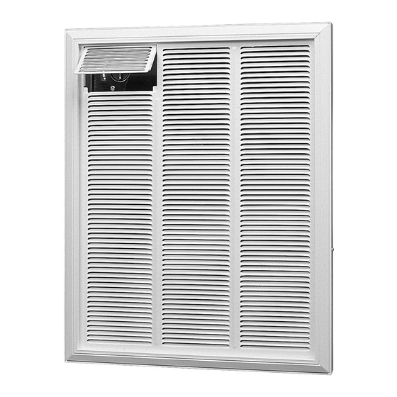
Remove heater from carton. The front grille and trim can
be lifted off assembly, and placed in carton to prevent
damage. Remove screws securing heater assembly to
the recess box and separate. (Fig. 1).
Note - Mount the heater a minimum of 12" (30.5cm) from the
finished floor, and a minimum of 6" (15cm) from any
vertical surface if installed in the ceiling.
Recessed Installation
1.
The recess box provided with the heater is designed for
attachment between studs placed on 16" (40.6cm)
centres. If different spacing exists, construct frame tosuit
the box in order to avoid any vibration and noise caused
by loose mounting (Fig. 2a).
2.
Note orientation of box ("TOP" shown on recess box) and
secure to studs using four holes provided on side flanges,
ensuring these flanges are flush with finished surface of
wall or ceiling (Fig. 2b).
Surface Installation
1.
Secure optional surface mount box (Part No. RFP8D) by
angling screws through holes provided in rear of surface
box into studs or finished surface.
2.
Position surface box into recess box and secure with four
screws provided in parts bag of surface box.
Fig. 2
(a)
19 3/4"
(50cm)
MIN. 12"
(30.5cm)
NOTE: Dimensions are shown as size of rough opening in stud wall
14 1/4"
(36cm)
SIDE FLANGES
Series RFI-D for wall or ceiling mounting
Fig.1
GROUND
SCREW
(b)
15"
(38cm)
FINISHED WALL
SURFACE
FINISHED FLOOR
Forced Air Heater
FRONT PANEL
(GRILLE) & TRIM FRAME
HEATER
ASSEMBLY
RECESS BOX
7/8" (22MM) DIA. KNOCKOUT
14 1/4"
(36cm)
3 5/8"
(9cm)
19 3/4"
(50cm)
MIN. 12"
(30.5cm)
Advertisement

Related Manuals for Dimplex RFI815D31


Summary of Contents for Dimplex RFI815D31
- Page 1 Forced Air Heater Series RFI-D for wall or ceiling mounting 1-888-346-7539 Fig.1 Installation, Operation & Maintenance Instructions FRONT PANEL (GRILLE) & TRIM FRAME Remove heater from carton. The front grille and trim can be lifted off assembly, and placed in carton to prevent damage.
- Page 2 Fig. 3 (A)Place frame over top of tabs. (B) Push in at bottom until frame is flush with front panel. (C) Insert two screws to hold frame in place. Supply Wiring and Heater Installation Insert approximately 15” (38cm) of supply wire into recess box through knockout provided in upper left hand corner (Fig. 2b). Wire should be rated for a minimum of 75°C (167°F) Connect power supply to terminals provided marked L1 and L2.
-
Page 3: Wiring Diagram
WIRING DIAGRAM 1 WIRING DIAGRAM 2 BUILT IN THERMOSTAT (FACTORY WIRED) S.P. “LINE” VOLTAGE REMOTE THERMOSTAT L2 (L-277V) L2 (L-277V) SUPPLY SUPPLY L1 (N-277V) L1 (N-277V) REMOTE SP STAT CYCLE CYCLE UNIT UNIT CAPACITOR CAPACITOR GND. GND. THERMAL THERMAL CUT OUT CUT OUT FAN DELAY FAN DELAY... - Page 4 7200610100 REV10...