Sign In
Upload
Download
Table of Contents
Contents
Add to my manuals
Delete from my manuals
Share
URL of this page:
HTML Link:
Bookmark this page
Add
Manual will be automatically added to "My Manuals"
Print this page
×
Bookmark added
×
Added to my manuals
Manuals
Brands
Hobart Manuals
Welding System
Handler 135
Owner's manual
Hobart Handler 135 Owner's Manual
Handler 135; handler 175; h-10 gun
Hide thumbs
1
2
Table Of Contents
3
4
5
6
7
8
9
10
11
12
13
14
15
16
17
18
19
20
21
22
23
24
25
26
27
28
29
30
31
32
33
34
35
36
37
38
39
40
41
42
43
44
45
46
47
48
page
of
48
Go
/
48
Contents
Table of Contents
Troubleshooting
Bookmarks
Table of Contents
Table of Contents
Section 1 - Safety Precautions - Read before Using
Symbol Usage
Arc Welding Hazards
Additional Symbols for Installation, Operation, and Maintenance
Principal Safety Standards
EMF Information
Section 1 - Consignes de Securite - Lire Avant Utilisation
Signification des Symboles
Dangers Relatifs Au Soudage À L'arc
Dangers Supplémentaires en Relation Avec L'installation, Le Fonctionnement Et la Maintenance
Principales Normes de Sécurité
Information Sur Les Champs Électromagnétiques
Section 2 - Specifications
Specifications
Duty Cycle and Overheating
Volt-Ampere Curves
Section 3 - Installation
Installing Welding Gun
Installing Work Clamp
Process/Polarity Table
Changing Polarity
Installing Gas Supply
Selecting a Location and Connecting Input Power for 115 VAC Model
Selecting a Location and Connecting Input Power for 230 VAC Model
Electrical Service Guide for 230 VAC Model
Installing Wire Spool and Adjusting Hub Tension
Threading Welding Wire
Section 4 - Operation
Controls
Weld Parameters for 115 VAC Model
Weld Parameters for 230 VAC Model
Section 5 - Maintenance &Troubleshooting
Routine Maintenance
Overload Protection
Drive Motor Protection
Changing Drive Roll or Wire Inlet Guide
Replacing Gun Contact Tip
Cleaning or Replacing Gun Liner
Replacing Switch And/Or Head Tube
Troubleshooting Table
Section 6 - Electrical Diagram
Section 7 - Mig Welding (Gmaw) Guidelines
Typical MIG Process Connections
Typical MIG Process Control Settings
Holding and Positioning Welding Gun
Conditions that Affect Weld Bead Shape
Gun Movement During Welding
Poor Weld Bead Characteristics
Good Weld Bead Characteristics
Troubleshooting - Excessive Spatter
Troubleshooting - Porosity
Troubleshooting - Excessive Penetration
Troubleshooting - Lack of Penetration
Troubleshooting - Incomplete Fusion
Troubleshooting - Burn-Through
Troubleshooting - Waviness of Bead
Troubleshooting - Distortion
Common MIG Shielding Gases
Section 8 - Parts List
Advertisement
Quick Links
1
Specifications
2
Installing Wire Spool and Adjusting Hub Tension
3
Section 8 - Parts List
Download this manual
Handler 135 / 175
And H-10 Gun
OM-944
196 639C
October 2001
Processes
MIG (GMAW) Welding
Flux Cored (FCAW) Welding
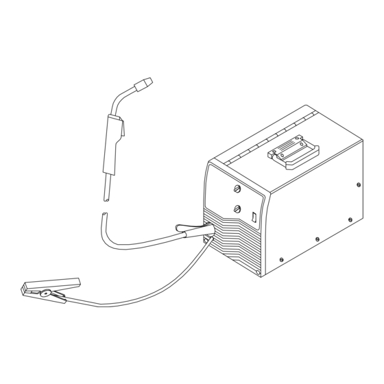
Description
Arc Welding Power Source And
Wire Feeder
Table of
Contents
Previous
Page
Next
Page
1
2
3
4
5
Advertisement
Table of Contents
Troubleshooting
SECTION 5 - MAINTENANCE &TROUBLESHOOTING
26
Troubleshooting Table
30
Troubleshooting - Excessive Spatter
38
Troubleshooting - Lack Of Penetration
39
Troubleshooting - Waviness Of Bead
40
Need help?
Do you have a question about the Handler 135 and is the answer not in the manual?
Ask a question
Questions and answers
Related Manuals for Hobart Handler 135
Welding System Hobart Handler 140 Owner's Manual
(48 pages)
Welding System Hobart 1435 Owner's Manual
Engine driven welding generator (60 pages)
Welding System Hobart 0 Specifications
All-in-one 10,000-watt ac generator and dc welder 211801 (4 pages)
Welding System Hobart CHAMPION 10,000 Owner's Manual
Stick (smaw) welding, engine driven welding generator (69 pages)
Welding System Hobart Champion 10,000 Owner's Manual
Stick (smaw) welding, engine driven welding generator (64 pages)
Welding System Hobart Handler 125 Owner's Manual
Flux cored (fcaw) welding, mig (gmaw) welding ,(optional), arc welding power source and wire feeder (52 pages)
Welding System Hobart Handler 125 Owner's Manual
Flux cored (fcaw) welding, mig (gmaw) welding (optional), arc welding power source and wire feeder (48 pages)
Welding System Hobart Handler 125 Specifications
115v wire feed welder (2 pages)
Welding System Hobart H100S2-10 Owner's Manual
(40 pages)
Welding System Hobart Handler 140 Specifications
115v wire feed welder (4 pages)
Welding System Hobart Handler 140 Technical Manual
(48 pages)
Welding System Hobart Handler 125 EZ Owner's Manual
(48 pages)
Welding System Hobart Handler 190 Technical Manual
(48 pages)
Welding System Hobart Handler 130 XL Owner's Manual
(37 pages)
Welding System Hobart Stickmate 160i Owner's Manual
(40 pages)
Welding System Hobart Champion 145 Owner's Manual
(48 pages)
This manual is also suitable for:
Handler 175
H-10 gun
H-10
Table of Contents
Save PDF
Print
Rename the bookmark
Delete bookmark?
Delete from my manuals?
Login
Sign In
OR
Sign in with Facebook
Sign in with Google
Upload manual
Upload from disk
Upload from URL


Need help?
Do you have a question about the Handler 135 and is the answer not in the manual?
Questions and answers