
Related Manuals for Hobart Champion 145


Summary of Contents for Hobart Champion 145
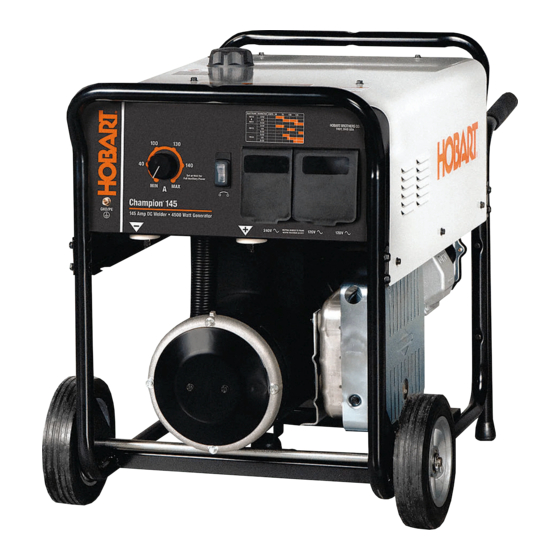
- Page 1 OM-250 200B 2012−08 Processes Stick (SMAW) Welding Description Engine Driven Welding Generator Champion 145 File: Engine Drive www.HobartWelders.com...
-
Page 2: Table Of Contents
Amperage Selection Table For Stick (SMAW) Electrodes ......Hobart is registered to the ISO 9001 Quality 6-4. -
Page 3: Section 1 − Safety Precautions − Read Before Using
SECTION 1 − SAFETY PRECAUTIONS − READ BEFORE USING rom_2011−10 Protect yourself and others from injury — read, follow, and save these important safety precautions and operating instructions. 1-1. Symbol Usage DANGER! − Indicates a hazardous situation which, if Indicates special instructions. not avoided, will result in death or serious injury. - Page 4 D Do not weld on containers that have held combustibles, or on FUMES AND GASES can be hazardous. closed containers such as tanks, drums, or pipes unless they are properly prepared according to AWS F4.1 and AWS A6.0 (see Welding produces fumes and gases. Breathing these Safety Standards).
-
Page 5: Engine Hazards
1-3. Engine Hazards EXHAUST SPARKS can cause fire. BATTERY EXPLOSION can injure. D Do not let engine exhaust sparks cause fire. D Always wear a face shield, rubber gloves, and protective clothing when working on a battery. D Use approved engine exhaust spark arrestor in required areas —... -
Page 6: Additional Symbols For Installation, Operation, And Maintenance
HOT METAL from air arc cutting and MOVING PARTS can injure. gouging can cause fire or explosion. D Keep away from moving parts such as fans, D Do not cut or gouge near flammables. belts and rotors. D Watch for fire; keep extinguisher nearby. D Keep all doors, panels, covers, and guards closed and securely in place. - Page 7 BATTERY CHARGING OUTPUT and BATTERY STATIC (ESD) can damage PC boards. EXPLOSION can injure. D Put on grounded wrist strap BEFORE handling Battery charging not present on all models. boards or parts. D Use proper static-proof bags and boxes to D Always wear a face shield, rubber gloves, and protective store, move, or ship PC boards.
-
Page 8: California Proposition 65 Warnings
1-6. California Proposition 65 Warnings For Gasoline Engines: Welding or cutting equipment produces fumes or gases which contain chemicals known to the State of California to Engine exhaust contains chemicals known to the State of cause birth defects and, in some cases, cancer. (California California to cause cancer, birth defects, or other reproduc- Health &... -
Page 9: Section 2 − Consignes De Sécurité − Lire Avant Utilisation
SECTION 2 CONSIGNES DE SÉCURITÉ − LIRE AVANT − UTILISATION fre_rom_2011−10 Pour écarter les risques de blessure pour vous−même et pour autrui — lire, appliquer et ranger en lieu sûr ces consignes relatives aux précautions de sécurité et au mode opératoire. 2-1. - Page 10 Il reste une TENSION DC NON NÉGLIGEABLE dans les LES RAYONS DE L’ARC peuvent sources de soudage onduleur UNE FOIS le moteur coupé. provoquer des brûlures dans les yeux et sur la peau. D Couper l’alimentation du poste et décharger les condensateurs d’entrée comme indiqué...
-
Page 11: Dangers Existant En Relation Avec Le Moteur
D Protéger les bouteilles de gaz comprimé d’une chaleur excessive, LE BRUIT peut affecter l’ouïe. des chocs mécaniques, des dommages physiques, du laitier, des flammes ouvertes, des étincelles et des arcs. Le bruit des processus et des équipements peut D Placer les bouteilles debout en les fixant dans un support station- affecter l’ouïe. -
Page 12: Dangers Liés À L'air Comprimé
LA VAPEUR ET LE LIQUIDE DE L’ACIDE DE LA BATTERIE peut pro- REFROIDISSEMENT CHAUD peuvent voquer des brûlures dans les YEUX et provoquer des brûlures. sur la PEAU. D Il est préférable de vérifier le liquide de refroi- D Ne pas renverser la batterie. dissement une fois le moteur refroidi pour éviter D Remplacer une batterie endommagée. -
Page 13: Dangers Supplémentaires En Relation Avec L'installation, Le Fonctionnement Et La Maintenance
détendre la pression et s’assurer que le circuit d’air ne peut être L’INHALATION D’AIR COMPRIMÉ risque mis sous pression par inadvertance. de provoquer des blessures ou même D Demander seulement à un personnel qualifié d’enlever la mort. les dispositifs de sécurité ou les recouvrements pour effectuer, s’il y a lieu, des travaux d’entretien et de dépannage. - Page 14 LA SORTIE DE RECHARGE et L’EXPLO- LES CHARGES ÉLECTROSTATI- SION BATTERIE peuvent QUES peuvent endommager les provoquer des blessures. circuits imprimés. D Établir la connexion avec la barrette de terre La recharge de batterie n’existe pas sur tous les avant de manipuler des cartes ou des pièces. modèles.
-
Page 15: Proposition Californienne 65 Avertissements
2-6. Proposition californienne 65 Avertissements Pour les moteurs à essence : Les équipements de soudage et de coupage produisent des fumées et des gaz qui contiennent des produits chimiques Les gaz d’échappement des moteurs contiennent des pro- dont l’État de Californie reconnaît qu’ils provoquent des mal- duits chimiques dont l’État de Californie reconnaît qu’ils formations congénitales et, dans certains cas, des cancers. -
Page 16: Section 3 − Definitions
Complete Parts List available at www.HobartWelders.com SECTION 3 − DEFINITIONS 3-1. Additional Safety Symbols And Definitions Some symbols are found only on CE products. Warning! Watch Out! There are possible hazards as shown by the symbols. Safe1 2012−05 Never use generator inside a home or garage, even if doors and win- dows are open. -
Page 17: Section 4 − Specifications
Complete Parts List available at www.HobartWelders.com SECTION 4 − SPECIFICATIONS 4-1. Weld, Power, And Engine Specifications Weld Maximum Welding Rated Generator Fuel Output Open Circuit Engine Mode Welding Output Power Rating Capacity Range Voltage Single-Phase, Briggs & Stratton 4.5 kVA/kW (Surge) Intek 4 kVA/kW Air-Cooled,... -
Page 18: Fuel Consumption
Complete Parts List available at www.HobartWelders.com 4-3. Fuel Consumption 1.20 1.00 0.80 0.60 0.40 0.20 0.00 DC WELD AMPERES at RATED DUTY CYCLE 250194 4-4. Duty Cycle Duty cycle is the percentage of 10 minutes that unit can weld at rated load without overheating. -
Page 19: Generator Power Curve
Complete Parts List available at www.HobartWelders.com 4-5. Generator Power Curve The ac generator power curves show the generator power available in amperes at the receptacles. 240 VAC 120 VAC AC POWER AMPERES 250 192 4-6. Volt-Ampere Curves The volt-ampere curve shows the minimum and maximum voltage and amperage output capabilities of the welding generator. -
Page 20: Section 5 − Installation
Complete Parts List available at www.HobartWelders.com SECTION 5 − INSTALLATION 5-1. Serial Number And Rating Label Location The serial number and the rating information for this product is located on the stator. Use rating label to determine input power requirements and/or rated output. -
Page 21: Engine Prestart Checks
Complete Parts List available at www.HobartWelders.com 5-4. Engine Prestart Checks Check all fluids daily. Engine must be cold and on a level surface. Unit is shipped with 10W30 engine oil. Engine stops if oil level gets too low. 1/2 in (13 mm) Fuel Valve Full... -
Page 22: Weld Output Terminals
Complete Parts List available at www.HobartWelders.com 5-5. Weld Output Terminals Negative (−) Weld Output Terminal Positive (+) Weld Output Terminal For Direct Current Electrode Posit- ive (DCEP), connect electrode holder to Positive (+) terminal and work cable to Negative (−) terminal. For Direct Current Electrode Neg- ative (DCEN), reverse cable con- nections. -
Page 23: Selecting Weld Cable Sizes
**Weld cable size (AWG) is based on either a 4 volts or less drop or a current density of at least 300 circular mils per ampere. ( ) = mm for metric use ***For distances longer than those shown in this guide, call a factory applications rep. at 920-735-4505 (Miller) or 1-800-332-3281 (Hobart). Ref. S-0007-J 2011−07 Notes... -
Page 24: Section 6 − Operating The Welding Generator
Complete Parts List available at www.HobartWelders.com SECTION 6 − OPERATING THE WELDING GENERATOR 6-1. Controls (See Section 6-2) 251 051 / 251 052 / 250 186-B OM-250 200 Page 22... -
Page 25: Description Of Controls (See Section 6-1)
Complete Parts List available at www.HobartWelders.com 6-2. Description Of Controls (See Section 6-1) Engine Switch D Pull starter handle until engine starts. Amperage Control Use control to select weld amperage. Control Use switch to control ignition circuit, and to D Move Choke control to the left (Run) as may be adjusted while welding. -
Page 26: Section 7 − Operating Auxiliary Equipment
Complete Parts List available at www.HobartWelders.com SECTION 7 − OPERATING AUXILIARY EQUIPMENT The welding generator provides power while welding and with the Amperage control in any position. However, under these conditions equipment connected to the welding generator may be subject to larger than normal voltage fluctuations. It is recommended that only lamps be powered under these conditions. -
Page 27: Gfci Receptacle Information, Resetting And Testing
Complete Parts List available at www.HobartWelders.com 7-2. GFCI Receptacle Information, Resetting And Testing Test and reset GFCI only at Run speed and with controls set for full generator power. RotGFCI2 2012−05 disconnect power to the faulty equipment. power) speed. Set front panel amperage Use GFCI protection when operat- A GFCI receptacle does not protect against controls at Max to achieve full generator... -
Page 28: Section 8 − Maintenance
Complete Parts List available at www.HobartWelders.com SECTION 8 − MAINTENANCE 8-1. Routine Maintenance Stop engine before maintaining. See Engine Manual and Maintenance Label Recycle engine for important start-up, service, and storage fluids. information. Service engine more often if used in severe conditions. n = Check Z = Change ~ = Clean... -
Page 29: Servicing Air Cleaner
Complete Parts List available at www.HobartWelders.com 8-2. Servicing Air Cleaner Stop engine. NOTICE − Do not run engine with- out air cleaner or with dirty element. 1. Cover 2. Precleaner Remove air cleaner cover. Wash precleaner with soap and water so- lution. -
Page 30: Section 9 − Troubleshooting
Complete Parts List available at www.HobartWelders.com SECTION 9 − TROUBLESHOOTING 9-1. Troubleshooting A. Welding Trouble Remedy No weld output; no generator power Be sure all equipment is disconnected from receptacles when starting unit. output at ac receptacles. Have Factory Authorized Service Agent check brushes, slip rings, rotor, stator, integrated rectifier SR1, and capacitor C1. -
Page 31: Section 10 − Parts List
Complete Parts List available at www.HobartWelders.com Trouble Remedy Erratic output at generator power ac Check fuel level. receptacles. Check Amperage control setting. Set Amperage control at Max for generator power. Check receptacle wiring and connections. Check governor linkage for smooth, non-binding operation. Service air cleaner according to engine manual. -
Page 32: Section 11 − Electrical Diagrams
SECTION 11 − ELECTRICAL DIAGRAMS 250 189-A Figure 11-1. Circuit Diagram For Welding Generator OM-4418 Page 30... -
Page 33: Section 12 − Generator Power Guidelines
SECTION 12 − GENERATOR POWER GUIDELINES The views in this section are intended to be representative of all engine-driven welding generators. Your unit may differ from those shown. 12-1. Selecting Equipment Generator Power Receptacles − Neutral Bonded To Frame 3-Prong Plug From Case Grounded Equipment 2-Prong Plug From Double Insulated Equipment... - Page 34 12-3. Grounding When Supplying Building Systems Equipment Grounding Terminal Grounding Cable Use #8 AWG or larger insulated copper wire. GND/PE Ground Device Use ground device as stated in electrical codes. Ground generator to system earth ground if supplying power to a premises (home, shop, farm) wiring system.
- Page 35 12-5. Approximate Power Requirements For Industrial Motors Industrial Motors Rating Starting Watts Running Watts Split Phase 1/8 HP 1/6 HP 1225 1/4 HP 1600 1/3 HP 2100 1/2 HP 3175 Capacitor Start-Induction Run 1/3 HP 2020 1/2 HP 3075 3/4 HP 4500 1400 1 HP...
- Page 36 12-7. Approximate Power Requirements For Contractor Equipment Contractor Rating Starting Watts Running Watts Hand Drill 1/4 in. 3/8 in. 1/2 in. Circular Saw 6-1/2 in. 7-1/4 in. 8-1/4 in. 1400 1400 Table Saw 9 in. 4500 1500 10 in. 6300 1800 Band Saw 14 in.
- Page 37 12-8. Power Required To Start Motor Single-Phase Induction Motor Starting Requirements Motor Start Code KVA/HP 10.0 11.2 12.5 14.0 Motor Start Code Running Amperage Motor HP Motor Voltage To find starting amperage: Step 1: Find code and use table to find kVA/HP.
- Page 38 12-10. Typical Connections To Supply Standby Power Have only qualified persons perform these connections according to all applicable codes and safety practices. Properly install, ground, and operate this equipment ac- cording to its Owner’s Manu- al and national, state, and lo- cal codes.
- Page 39 12-11. Selecting Extension Cord (Use Shortest Cord Possible) Cord Lengths for 120 Volt Loads Use GFCI protection when operating auxiliary equipment. If unit does not have GFCI receptacles, use GFCI-protected exten- sion cord. Do not use GFCI receptacles to power life support equipment. Maximum Allowable Cord Length in ft (m) for Conductor Size (AWG)* Current Load (Watts)
-
Page 40: Section 13 − Stick Welding (Smaw) Guidelines
SECTION 13 − STICK WELDING (SMAW) GUIDELINES 13-1. Stick Welding Procedure Weld current starts when electrode touches work- piece. Weld current can damage electronic parts in vehicles. Disconnect both battery cables before welding on a vehicle. Place work clamp as close to the weld as Equipment Needed: Tools Needed: possible. - Page 41 13-2. Electrode and Amperage Selection Chart 6010 DEEP 3/32 MIN. PREP, ROUGH HIGH SPATTER 6011 DEEP 6010 5/32 & 6013 EP,EN GENERAL 3/16 6011 7/32 SMOOTH, EASY, 7014 EP,EN FAST 1/16 LOW HYDROGEN, 7018 5/64 STRONG 3/32 FLAT SMOOTH, EASY, 7024 EP,EN HORIZ...
- Page 42 13-4. Positioning Electrode Holder End View Of Work Angle Side View Of Electrode Angle ° ° ° ° Groove Welds ° ° ° ° Fillet Welds S-0060 13-5. Poor Weld Bead Characteristics Large Spatter Deposits Rough, Uneven Bead Slight Crater During Welding Bad Overlap Poor Penetration S-0053-A...
- Page 43 13-7. Conditions That Affect Weld Bead Shape Weld bead shape is affected electrode angle, length, travel speed, and thick- ness of base metal. Correct Angle Angle Too Large ° - ° Angle Too Small Electrode Angle Drag Spatter Arc Length Normal Too Long Too Short...
- Page 44 13-9. Groove (Butt) Joints Tack Welds Prevent edges of joint from draw- ing together ahead of electrode by tack welding the materials in posi- tion before final weld. Square Groove Weld Good for materials up to 3/16 in. (5 mm) thick. Single V-Groove Weld Good for materials 3/16 −...
- Page 45 13-12. Weld Test Vise Weld Joint Hammer Strike weld joint in direction shown. A good weld bends over but does not break. 2 To 3 in. (51-76 mm) 2 To 3 in. (51-76 mm) 1/4 in. (6.4 mm) S-0057-B 13-13. Troubleshooting Porosity −...
- Page 46 Lack Of Penetration − shallow fusion between weld metal and base metal. Lack of Penetration Good Penetration Possible Causes Corrective Actions Improper joint preparation. Material too thick. Joint preparation and design must provide access to bottom of groove. Improper weld technique. Keep arc on leading edge of weld puddle.
- Page 47 Effective January 1, 2012 5/3/1 WARRANTY applies to all Hobart welding equipment, plasma cutters and spot welders with a Warranty Questions? serial number preface of MC or newer. Call This limited warranty supersedes all previous Hobart warranties and is exclusive with 1-800-332-3281 no other guarantees or warranties expressed or implied.
- Page 48 Thank you for purchasing Hobart. Our trained technical support team is dedicated to your satisfaction. For questions regarding performance, op- eration, or service, contact us! Resources Available Always provide Model Name and Serial/Style Number. To locate a Service Center: Call 1-800-332-3281 or visit our website at www.HobartWelders.com/wheretobuy...
Need help?
Do you have a question about the Champion 145 and is the answer not in the manual?
Questions and answers