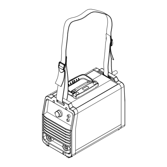
Do you have a question about the Stickmate 160i and is the answer not in the manual?
Questions and answers
greg
April 5, 2025
what wattage generater will run the hobart 160i stick welder
1 comments:
Mr. Anderson
April 5, 2025
The Hobart Stickmate 160i welder requires a maximum input of 2.48 kVA at 120V. To determine the required generator wattage, convert kVA to kilowatts (kW) using the power factor (assume ~0.8 for welders), then convert to watts:
2.48 kVA × 0.8 = 1.984 kW → 1,984 watts (at 120V)
For 240V use, double the voltage reduces current draw, but wattage remains about the same.
To ensure reliable operation, a generator with at least 20–25% more capacity is recommended. Therefore, a generator rated at 2,500–3,000 watts minimum is needed.
SECTION 1 − SAFETY PRECAUTIONS - READ BEFORE USING som 2015−09 Protect yourself and others from injury — read, follow, and save these important safety precautions and operating instructions. 1-1. Symbol Usage DANGER! − Indicates a hazardous situation which, if Indicates special instructions.
Page 6
D Remove stick electrode from holder or cut off welding wire at FUMES AND GASES can be hazardous. contact tip when not in use. D Wear body protection made from durable, flame−resistant material Welding produces fumes and gases. Breathing (leather, heavy cotton, wool). Body protection includes oil-free these fumes and gases can be hazardous to your clothing such as leather gloves, heavy shirt, cuffless trousers, high health.
1-3. Additional Symbols For Installation, Operation, And Maintenance FIRE OR EXPLOSION hazard. MOVING PARTS can injure. D Do not install or place unit on, over, or near D Keep away from moving parts such as fans. combustible surfaces. D Keep all doors, panels, covers, and guards D Do not install unit near flammables.
1-4. California Proposition 65 Warnings Welding or cutting equipment produces fumes or gases This product contains chemicals, including lead, known to which contain chemicals known to the State of California to the state of California to cause cancer, birth defects, or other cause birth defects and, in some cases, cancer.
SECTION 2 − CONSIGNES DE SÉCURITÉ − LIRE AVANT UTILISATION fre_som_2015−09 Pour écarter les risques de blessure pour vous−même et pour autrui — lire, appliquer et ranger en lieu sûr ces consignes relatives aux précautions de sécurité et au mode opératoire. 2-1.
Page 10
chauffement ou un incendie. Avant de commencer le soudage, vérifier LES PIÈCES CHAUDES peuvent et s’assurer que l’endroit ne présente pas de danger. provoquer des brûlures. D Déplacer toutes les substances inflammables à une distance de D Ne pas toucher à mains nues les parties chaudes. 10,7 m de l’arc de soudage.
D Tenir les bouteilles éloignées des circuits de soudage ou autres LE BRUIT peut endommager l’ouïe. circuits électriques. D Ne jamais placer une torche de soudage sur une bouteille à gaz. Le bruit des processus et des équipements peut affecter l’ouïe. D Une électrode de soudage ne doit jamais entrer en contact avec D Porter des protections approuvées pour les une bouteille.
RAYONNEMENT HAUTE LE SOUDAGE À L’ARC risque de FRÉQUENCE (H.F.) risque provoquer des interférences. provoquer des interférences. D L’énergie électromagnétique risque D Le rayonnement haute fréquence (H.F.) peut provoquer des interférences pour l’équipement provoquer des interférences avec les équi- électronique sensible tel que les ordinateurs et l’équipement commandé...
A complete Parts List is available at www.HobartWelders.com SECTION 3 − DEFINITIONS 3-1. Miscellaneous Symbols And Definitions Some symbols are found only on CE products. Direct Current Amperage Negative Shielded Metal Arc Input Power Or Welding (SMAW) Voltage Input Voltage Single Phase Rated No-Load Voltage (OCV)
For future reference, write serial number in space provided on back cover of this manual. 4-2. Unit Specifications Do not use information in unit specifications table to determine electrical service requirements. See Sections 5-8 thru 5-10 for information on con- necting input power. A. Stickmate 160i Maximum Amperage Maximum...
−4 to 131°F (−20 to 55°C) *Output is derated at temperatures above 104°F (40°C). Temp_2016- 07 4-4. Duty Cycle Charts A. Stickmate 160i Duty Cycle is percentage of 10 min- utes that unit can weld at rated load without overheating.
Page 16
A complete Parts List is available at www.HobartWelders.com B. Stickmate 210i Duty Cycle is percentage of 10 min- utes that unit can weld at rated load without overheating. If unit overheats, thermostat(s) opens, output stops, and cooling fan runs. Wait fifteen minutes for unit to cool.
A complete Parts List is available at www.HobartWelders.com 4-5. Volt-Ampere Curves The volt-ampere curves show the minimum and maximum voltage A. Stickmate 160i (120 Volt Input) and amperage output capabilities. Curves of other settings fall be- tween the curves shown.
A complete Parts List is available at www.HobartWelders.com SECTION 5 − INSTALLATION 5-1. Selecting a Location Do not move or operate unit where it could tip. Movement Location And Airflow Special installation may be required where gasoline or volatile liquids are present − see NEC Article 511 or CEC Section 20.
A complete Parts List is available at www.HobartWelders.com 5-2. Installing Electrode Holder And Work Clamp Removing Barrel From Electrode Holder Barrel Barrel Set Screw Electrode Holder Loosen barrel set screw. Slide barrel away from electrode holder. Installing Electrode Cable and Barrel onto Electrode Holder Electrode Cable From Unit (Has Bare Conductors on End)
A complete Parts List is available at www.HobartWelders.com 5-4. Connecting To Weld Output Terminals Turn off power before connecting to weld output terminals. Do not use worn, damaged, un- dersized, or repaired cables. Negative (−) Weld Output Terminal Positive (+) Weld Output Terminal Dinse Weld Connector Insert Dinse connector fully into termi- nal.
A complete Parts List is available at www.HobartWelders.com 5-6. Multi−Voltage Plug Adapter (MVP) Connection (Stickmate 160i Only) Selecting Plug Adapter Do not cut off power cord connector and rewire. The power cord connector and plugs adapters will work with standard NEMA receptacles.
5-8. Electrical Service Guide Elec Serv 2017-01 A. Stickmate 160i Failure to follow these electrical service guide recommendations could create an electric shock or fire hazard. These recommenda- tions are for a dedicated circuit sized for the rated output and duty cycle of the welding power source.
A complete Parts List is available at www.HobartWelders.com 5-9. Connecting 120 Volt Input Power (Stickmate 160i Only) Installation must meet National and Local Codes − have only qualified persons make this installation. Special installation required where gasoline or volatile liquids are present − see NEC Ar- ticle 511 or CEC Section 20.
A complete Parts List is available at www.HobartWelders.com 5-10. Connecting 240 Volt Input Power Installation must meet all National and Local Codes − have only qualified persons make this installation. Disconnect and lockout/tagout in- put power before installing recep- tacle. Follow established proced- ures regarding the installation and removal of lockout/tagout devices.
A complete Parts List is available at www.HobartWelders.com SECTION 6 − OPERATION 6-1. Controls A. Stickmate 160i Amperage Adjustment Control Use control to select desired weld amperage. Power Indicator Light Lamp goes on when unit is on. Over Temperature Light...
Page 26
A complete Parts List is available at www.HobartWelders.com B. Stickmate 210i Amperage Adjustment Control Use control to select desired weld amperage. Power Indicator Light Light goes on when unit is on. Over Temperature Light Light goes on when unit has stopped due to overheating (see Section 4-4).
A complete Parts List is available at www.HobartWelders.com SECTION 7 − MAINTENANCE & TROUBLESHOOTING 7-1. Routine Maintenance Disconnect power Maintain more often before maintaining. during severe conditions. n = Check Z = Change ~ = Clean l = Replace Reference * To be done by Factory Authorized Service Agent Every Months...
........♦OPTIONAL * Available at farm and tool supply retailers. ** Available at Hobart/Miller welding distributors. Notes Work like a Pro! Pros weld and cut safely.
SECTION 10 − STICK WELDING (SMAW) GUIDELINES 10-1. Stick Welding Procedure Weld current starts when electrode touches work- piece. Weld current can damage electronic parts in vehicles. Disconnect both battery Equipment Needed: Tools Needed: cables before welding on a vehicle. Place work clamp as close to the weld as possible.
Page 31
10-2. Electrode and Amperage Selection Chart 6010 DEEP 3/32 MIN. PREP, ROUGH HIGH SPATTER 6011 DEEP 6010 5/32 & 6013 EP,EN GENERAL 3/16 6011 7/32 SMOOTH, EASY, 7014 EP,EN FAST 1/16 LOW HYDROGEN, 7018 5/64 STRONG 3/32 FLAT SMOOTH, EASY, 7024 EP,EN 6013...
Page 32
10-4. Positioning Electrode Holder End View Of Work Angle Side View Of Electrode Angle After learning to start and hold an arc, practice running beads of weld metal on flat plates using a full electrode. ° ° Hold the electrode nearly per- pendicular to the work, although tilting it ahead (in the direction of °...
Page 33
10-7. Conditions That Affect Weld Bead Shape Weld bead shape is affected electrode angle, length, travel speed, and thick- ness of base metal. Correct Angle Angle Too Large ° - ° Angle Too Small Electrode Angle Drag Spatter Arc Length Normal Too Long Too Short...
Page 34
10-10. Welding Groove (Butt) Joints Tack Welds Prevent butt joint distortion by tack welding the materials in position before final weld. Workpiece distortion occurs when heat is applied locally to a joint. One side of a metal plate will “curl” up toward the weld.
Page 35
10-12. Weld Test Vise Weld Joint Hammer Strike the weld joint in the direction shown. A good weld bends over but does not break. If the weld breaks, examine it to determine the cause. If the weld is porous (many holes), the arc length was probably too long.
Page 36
Lack Of Penetration − shallow fusion between weld metal and base metal. Lack of Penetration Good Penetration Possible Causes Corrective Actions Improper joint preparation. Material too thick. Joint preparation and design must provide access to bottom of groove. Improper weld technique. Keep arc on leading edge of weld puddle.
Page 39
Effective January 1, 2017 5/3/1 WARRANTY applies to all Hobart welding equipment, plasma cutters and spot welders with a Warranty Questions? serial number preface of MH or newer. Call This limited warranty supersedes all previous Hobart warranties and is exclusive with 1-800-332-3281 no other guarantees or warranties expressed or implied.
Page 40
Thank you for purchasing Hobart. Our trained technical support team is dedicated to your satisfaction. For questions regarding performance, op- eration, or service, contact us! Resources Available Always provide Model Name and Serial/Style Number. To locate a Service Center: Call 1-800-332-3281 or visit our website at www.HobartWelders.com/wheretobuy...
Need help?
Do you have a question about the Stickmate 160i and is the answer not in the manual?
Questions and answers
what wattage generater will run the hobart 160i stick welder
The Hobart Stickmate 160i welder requires a maximum input of 2.48 kVA at 120V. To determine the required generator wattage, convert kVA to kilowatts (kW) using the power factor (assume ~0.8 for welders), then convert to watts:
2.48 kVA × 0.8 = 1.984 kW → 1,984 watts (at 120V)
For 240V use, double the voltage reduces current draw, but wattage remains about the same.
To ensure reliable operation, a generator with at least 20–25% more capacity is recommended. Therefore, a generator rated at 2,500–3,000 watts minimum is needed.
This answer is automatically generated