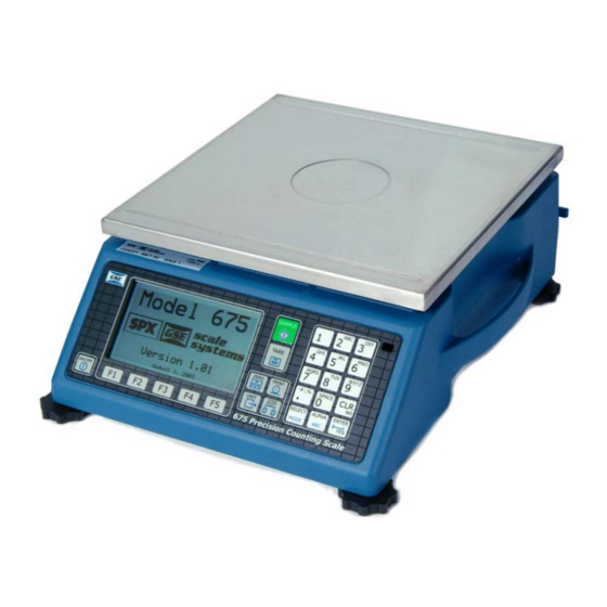
GSE 675 User Instructions
Precision parts counter
Hide thumbs
Also See for 675:
- Technical reference manual (430 pages) ,
- User manual (48 pages) ,
- User instruction manual (4 pages)

Related Manuals for GSE 675


Summary of Contents for GSE 675
- Page 1 Model 675 Precision Parts Counter User Instructions 39-10-40879 Issue AI September 2010...
- Page 2 All third party brands and product names used within this document are trademarks or registered trademarks of their respective holders. All Weigh-Tronix / GSE products bearing the Factory Mutual seal are designed and manufactured according to the guidelines set forth by Factory Mutual Research. It is the responsibility of owners to gain approval from their insurance company for the suitability of the Weigh-Tronix equipment and installation for their particular environment.
-
Page 3: Table Of Contents
Permanently Wired Equipment - Isolator Requirements ..........5 Safe Handling of Equipment with Batteries ..............5 Wet Conditions ......................5 Routine Maintenance ......................6 Cleaning the Model 675 ..................... 6 Training ..........................6 Sharp Objects ........................6 Display ..........................7 Keypad .......................... - Page 4 Known Loadcell Output ..................... 37 Multi - Scale Calibration .................... 38 Chapter 5 Troubleshooting ........................39 Operational Errors ......................39 Hardware Errors ....................... 40 ICalibration Errors ......................41 General Errors ......................... 41 Miscellaneous Errors ....................... 42 Communication Errors ..................... 43 Model 675 User Instructions...
-
Page 5: Chapter 1 General Information And Warnings
Cautions give information about procedures that, if not observed, could result in damage to equipment or corruption to and loss of data. NOTE: This is a Note symbol. Notes give additional and important information, hints and tips that help you to use your product. Model 675 User Instructions... -
Page 6: Installation
1.2 Installation THE MODEL 675 DOES NOT INCLUDE AN ON/OFF SWITCH AND, THEREFORE, MUST BE INSTALLED NEAR A POWER OUTLET SOCKET THAT IS EASILY ACCESSIBLE AND IN KEEPING WITH UL/CSA SAFETY STANDARDS. INFORMATION IMPORTANT! PRENDRE NOTE QUE LES MODEL 675 NE SONT PAS MUNIS D'INTERRUPTEURS "MARCHE / ARRÊT". -
Page 7: Electrical Installation
équivalent recommandé par le constructeur. Mettre au rebut les batteries usagées conformément aux instructions du fabricant. 1.4.4 Wet Conditions The Model 675 is not a washdown unit. Do not install near water. Model 675 User Instructions... -
Page 8: Routine Maintenance
ALWAYS TURN OFF THE MACHINE AND ISOLATE FROM THE POWER SUPPLY BEFORE STARTING ANY ROUTINE MAINTENANCE TO AVOID THE POSSIBILITY OF ELECTRIC SHOCK. Make sure that the Model 675 is placed securely on a flat and level surface. 1.6 Cleaning the Model 675 Table 1.1 Cleaning DOs and DON’Ts... -
Page 9: Display
The large graphic display features a backlight for use in poorly lit areas. 1.10 Keypad The Model 675 comes standard with a durable and versatile polymeric switch plate. The keys are large and easy to use. The keypad is easily cleaned with a damp cloth or non-abrasive cleaner. -
Page 10: Keypad Functions
Enter data or answer "YES" to a question. Enable/disable alpha entry mode. Refer to page 4 for setup information.Key Turn the scale on or off. Numeric keys used to manually enter a value for tare weight, average piece weight, sample size etc. Model 675 User Instructions... -
Page 11: Alpha Entry
1.10.2 Alpha Entry The Model 675 provides quick and easy alpha entry. The [ALPHA] key becomes the "Alpha enable/disable" key. The alpha characters assigned to each numeric key mimic a telephone layout with the addition of the [0/space] key. This allows additional ASCII characters to be accessed via the decimal point key. -
Page 12: Rear Panel
1.11 Rear Panel The Model 675 comes standard with 2 communication ports, which use Male DB-9 connectors. A remote base can also be connected to the SCALE 2 Female DB-9 connector. The positions that are shown with dotted lines are available for options such as scale 3 and 4, Ethernet, communication ports and setpoints. -
Page 13: Communication Port Connections
1.11.2 Communication Port Connections Comm port 1 and 2 are standard on the Model 675. Comm port 3 and Comm port 4 are optional. Refer to Table 4 for communication port pin outs. Table 1.4 Comm Port 1 - 4 Pin Out... -
Page 14: Fcc And Emc Declarations Of Compliance
Classe A prescrites dans le Règlement sur le brouillage radioélectrique edicté par le ministère des Communications du Canada. European Countries Table 1.8 WARNING: This is a Class A product. In a domestic environment, this product may cause radio interference in which the user may be required to take adequate measures. Model 675 User Instructions... -
Page 15: Chapter 2 Configuration
Configuration The Model 675 Precision Counting Scale comes from the factory with the Application Menu enabled. This is where you will choose the preferred method of parts counting or weighing. See the explanations of each method in this chapter. After each counting method are the instructions for setting up that method. -
Page 16: Quick Count Setup Menu
At this time you can choose the Quick Count mode by pressing [ENTER] (YES) or return to the Application Menu by pressing [F5] (Exit) or [CLR] (NO). The Quick Count file will load automatically and return to the Quick Count mode. Model 675 User Instructions... -
Page 17: Setup
Choose one of the display types and press [F5] (EXIT) to save the change and return to the main menu. Style 1 This is the classic GSE 2x5 display. The weight or quantity will be displayed in larger font while the prompts will be to the right of the weight display. Model 675 User Instructions... -
Page 18: Preset Print Formats
Style 2 This style incorporates the classic GSE 2x5 display along with two smaller displays, which will show other parameters. Press the [SELECT] key from Quick Count to toggle through the different parameter choices. Preset Print Formats The preset print formats are viewable on the LCD display. Use the [F3] left arrow and [F4] right arrow keys to view all transmit styles. -
Page 19: Advanced Setup Menu
NOTE: Press [F5] at any time to abort loading the Apps Menu. Scanner This tab was specifically designed to show the string received from a scanner. Scan a label and the raw scanner data will be shown on the display. Model 675 User Instructions... -
Page 20: F2 - Gse Custom
2.2 F2 - GSE Custom Presently APW Lookup is the only application offered under GSE Custom. 2.2.1 APW Lookup The APW LOOKUP offers the flexibility of storing and recalling part numbers. The average piece weight and part description will be stored and recalled with the part number. - Page 21 Setup Style Style Style Exit Modes See Advanced Menu Section for complete details Next Enable Disable Exit Print D-load Print Exit Part#s Part#s Formats Comm Comm Exit Comm Comm Exit Figure 2.2 APW Lookup Menu Structure Model 675 User Instructions...
-
Page 22: Setup
Model 675. 2.2.6 Display Style Different display styles are offered to help customize the Model 675 parts counter to fit your needs. Choose one of the display types and press [F5] (EXIT) to save the change and return to the main menu. - Page 23 Quantity Part # Style 2 This style incorporates the classic GSE 2x5 display and a second display, which will show three other parameters. Press the [SELECT] key from the Application Menu screen to toggle through the different parameter choices. Large Display...
-
Page 24: Set Modes
Press the [F5] (EXIT) key to save the format and return to the main menu. Print #1 6/30/10 Part# 123456 Description Drywall Screws 8.363 lb Gross QTY: 1.133 lb Tare 7.230 lb 0.0075 lb APW: Print #2 Part# 123456789 0.017823 Tare 2.5143 Model 675 User Instructions... - Page 25 Lot # APW: 0.0075 lb QTY: Tare 1.133 lb Print #5 - 9 Reserved for future use. Custom Print CREATE A CUSTOM TRANSMIT FORMAT! SEE THE TECH MANUAL FOR DETAILS CREATE AND LOAD AS TRANSMIT #130 Model 675 User Instructions...
-
Page 26: Advanced Setup Menu
Setup (Setup Mode Access) This tab allows access to the setup mode to make changes to parameters such as full scale, count accuracy and baud rate etc. Please refer to the Model 675 Service Manual for details on more advanced setups and configurations. -
Page 27: F3 - Gse Default
This mode will reset the Model 675 to GSE factory default status. Note: The preset applications will be lost. The Model 675 can still be used as a parts counter after it is factory defaulted. Refer to page 31 for more details on simple counting. - Page 28 Model 675 User Instructions...
-
Page 29: Chapter 3 Operation
This chapter will give detailed operating instructions on each preprogrammed mode. The Model 675 is designed to operate from the 5 soft keys or the dedicated keys of the keypad. The advantage of using the soft keys is they are placed in succession for easy operation. - Page 30 Use the [SELECT] key to check other modes such as the Tare weight and Average Piece Weight. The [F2] (Count) can be pressed to return to the count mode at any time. Model 675 User Instructions...
-
Page 31: Accumulate
- or - If a container is not used: Press the [F1] Sample or [SAMPLE] key without the sample pieces on the scale. The scale will tare to establish a net zero reference. 0 000 Model 675 User Instructions... - Page 32 Press the key associated with the desired field (see page 9 for details on alpha entry). Key in the text and press [ENTER]. Press [F2] to store the part number, APW, Lot #, Bin # and description. Model 675 User Instructions...
-
Page 33: Accumulate
3.3 GSE Default 3.3.1 Simple Keypad Sample Auto Tare Method Sampling Pieces: If a container is used - Place container on scale and press the [SAMPLE] key. The scale will automatically tare the container. Model 675 User Instructions... - Page 34 Place the sample on the scale. Key in the sample size and then press the [SAMPLE] key. The scale will accept the current weights as a sample and will display the quantity. Figure 3.2 Example[5] [0] [SAMPLE] Model 675 User Instructions...
-
Page 35: Chapter 4 Calibration
This selection is not available with linearization enabled. Temp Zero - Performs a calibration without removing the current gross weight. The zero reference determined during the last calibration is maintained. This selection is not available with linearization enabled. Model 675 User Instructions... -
Page 36: New Zero
- or - To exit the calibration mode without saving the new calibration, press [CLR] at the ENTER=SAVE prompt. Then press [ENTER] at the ENTER=UNDO prompt and again at the ENTER=EXIT prompt to exit the calibration mode. Model 675 User Instructions... -
Page 37: Last Zero
Access the calibration mode as described on page Select the Temp Zero calibration method as described in Calibration Methods page Model 675 User Instructions... -
Page 38: Only Zero
After establishing zero, CAL OK? is displayed suggesting that the calibration is acceptable. Accept the calibration by pressing [ENTER] at the CAL OK? prompt. - or - Repeat the calibration by pressing [CLR] at the CAL OK? prompt. Model 675 User Instructions... -
Page 39: Calibration Reset
- or - Press [ENTER] to accept the displayed value. The display prompts LC#x mVv (where 'x' is the load cell number) and then shows the mV/V value (0.1 - 5.0) last entered for this load cell. Model 675 User Instructions... -
Page 40: Multi - Scale Calibration
[ENTER]. Proceed with a calibration method as described in Calibration Methods on page After completing a calibration, the Keyin Scl# appears once again. Enter the next scale number to be calibrated, or press [CLR] to exit the calibration mode and save the new calibration data. Model 675 User Instructions... -
Page 41: Chapter 5 Troubleshooting
Troubleshooting This section describes all error codes generated by the Model 675. Most error codes show a two-digit code reference along with a short text message. Possible causes and remedies are described for each error. 5.1 Operational Errors Message Description Input signal less than negative full scale. -
Page 42: Hardware Errors
The stored data has a checksum error. Check all parameters or re-load setup. CoDE26 Setup The indicator cannot use the FRAM for data storage and is attempting to power-up again CoDE27 to cure the problem. BOOT! The FRAM is corrupted in the PIN section. CoDE29 error Model 675 User Instructions... -
Page 43: Icalibration Errors
An attempt to select a disabled scale was made. CoDE54 Scale Disbl The FRAM database is corrupt (valid signature, invalid checksum). Contact GSE. CoDE57 dbOpt Error A new FLASH file has been uploaded via the ReFlash or BDM flash utilities in order to CoDE60 upgrade the firmware. -
Page 44: Miscellaneous Errors
This is not an error. Press to acknowledge your entry, or [ENTER] to re-enter. Okay? ##### Upon each power-up, the Model 675 tests the integrity of its firmware. If the result is Cksum not correct this message is displayed and the scale is not usable. -
Page 45: Communication Errors
COMM port number on which the problem error occurred. The Model 675 did not check it's receive data register in time, thus missing a portX character. The 'X' in the error message represents the COMM port number on which error the problem occurred. - Page 46 Model 675 User Instructions...
- Page 48 Avery Weigh-Tronix USA 1000 Armstrong Dr. Fairmont MN 56031 USA Tel:507-238-4461 Fax:507-238-4195 Email: usinfo@awtxglobal.com www.wtxweb.com Avery Weigh-Tronix UK Foundry Lane, Smethwick, West Midlands, England B66 2LP Tel:+44 (0) 8453 66 77 88 Fax: +44 (0)121 224 8183 Email: info@awtxglobal.com www.averyweigh-tronix.com...
Need help?
Do you have a question about the 675 and is the answer not in the manual?
Questions and answers