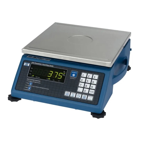
GSE 370 Technical Reference Manual
Precision counting scale
Hide thumbs
Also See for 370:
- Brochure & specs (6 pages) ,
- Technical reference manual (4 pages) ,
- User instructions (3 pages)

Related Manuals for GSE 370


Summary of Contents for GSE 370
- Page 1 Model 370 & Model 375 Precision Counting Scale Technical Reference Manual Version 1.0...
- Page 3 Model 370 & Model 375 Technical Reference Manual Version 1.0...
- Page 4 The information described in this manual is solely the property of GSE. No part of this manual may be reproduced or transmitted in any form or by any means, electronic or mechanical, including photocopying and recording and sold for any monetary figure without the express written permission of GSE.
-
Page 5: Table Of Contents
CHAPTER 1: INTRODUCTION ....................... 1 ..............................1 NCLOSURE ......................... 1 EPLACEMENT Load Cell Connections ........................... 2 ..............................2 EYPAD Model 370............................... 2 MODEL 375 ............................3 ..............................5 ISPLAY Annunciators ............................5 ........................5 ANEL ONNECTIONS Communication Port 1..........................6 Remote Display Connections........................ - Page 6 Setup Mode Errors ..........................74 Hardware Errors ..........................74 Calibration Errors..........................75 Communication Errors ......................... 75 Miscellaneous Errors ........................... 75 Viewing Setup ............................75 Information Mode Parameters (370 and 375)..................76 A/D C ........................ 77 ALIBRATION ROCEDURE ................77 NALOG...
-
Page 7: Chapter 1: Introduction
Chapter 1: INTRODUCTION This chapter describes the components of the Model 370/375 such as keypad, enclosure and display. Also included is wiring for the load cell and communication port. The enclosure is made of die cast aluminum with rib enforcement that includes built in carrying handles and a line cord wrap for ease of portability. -
Page 8: Load Cell Connections
All of the keys perform different functions. Some keys have more than one function. ODEL The Model 370 offers a 6-button durable and versatile Polymeric switch plate with large keys for ease of use. The keypad is easily cleaned with a damp cloth or non-abrasive cleaner. Each key is assigned two distinct functions. -
Page 9: Model 375
Toggles between display modes and/or restores modes and/or restores power to the Model Advances to the next setup power to the Model 370/375 (if auto-shutoff parameter. 370/375 (if auto-shutoff enabled) and/or toggles enabled). through standard sample sizes during a sample. - Page 10 ‘YES’ to query prompts. Toggles between display Toggles between display modes and/or restores power modes and/or restores to the Model 370/375 (if auto- Advances to the next power to the Model shutoff enabled) and/or toggles setup parameter. 370/375 (if auto-shutoff through standard sample sizes enabled).
-
Page 11: Display
The Model 370 and Model 375 come standard with a six digit, 7-segment bright green LED display. The Model 370 and Model 375 will display alphanumeric data, but due to the nature of 7- segment LED and the limitation of six digits, some information is abbreviated. -
Page 12: Communication Port 1
ISPLAY ONNECTIONS It is possible to connect a Model 370/375 to another 300 Series or 60 Series indicator and have the remote indicator display a copy of the master indicator or customize the display of the remote (slave) indicator. The remote (slave) indicator’s keypad will operate the master indicator. Refer to page 55 to configure the master and remote (slave) displays. -
Page 13: Chapter 2: Option Installation
6. Reinstall the enclosure bottom plate. Figure 2-1: RS-485 / 20 mA Option Installation RS-485 Connections (Comm Port 1) The Model 370/375 will be connected to a peripheral via the DB 9 connector on comm port 1. Refer to Table 2-1 for wiring connections. - Page 14 Table 2-1: RS-485 Comm Port 1 Connections Comm port 1 pin out Connection No connection TX (B+) TX (A-) ISO ground Ground RX (A-) RX (B+) Half Duplex (2-wire) Installing jumpers 1, 2 and 4 on the RS-485 option board electrically connects pin RX B(+) to pin TX B(+), and pin RX A(-) to pin TX A(-) on the option board.
-
Page 15: Ma Current Loop Option
Model 370/375). Installation Instructions DISCONNECT POWER! UNPLUG THE MODEL 370/375 TO INSURE DAMAGE WILL NOT OCCUR DURING OPTION INSTALLATION. Remove the six 8 mm screws (size) from the bottom plate. Separate the top enclosure... - Page 16 Only baud rates of 9600 baud and less are supported. Active/Passive The Tx output may be used as an active or passive output from the Model 370/375. Either active or passive is chosen depending upon which terminals are used for the connections. In active mode the Model 370/375 supplies the current.
-
Page 17: Analog Output Option
This section provides procedures for installing and configuring the analog output module. The analog output modules enable the Model 370/375 to generate a 0-10VDC, active 0-20mA or active 4-20mA output signal corresponding to the value of most operating parameters. For parameter setup see page 35. -
Page 18: Setpoint Option
High voltage AC, 2/in - 2/out Installation Instructions DISCONNECT POWER! UNPLUG THE MODEL 370/375 TO INSURE DAMAGE WILL NOT OCCUR DURING OPTION INSTALLATION Remove the (6) 38-31-8710 M5 x 0.8 x 10 mm screws from the enclosure bottom plate and set it aside. -
Page 19: Setpoint Card Connections
ONNECTIONS Using one of the software setpoint configurations (see General Setpoint Setup on page 36) in conjunction with the setpoint option board gives the Model 370/375 the ability to directly control external devices such as valves, relays, actuators, etc. There are up to three setpoint outputs available. The activation and deactivation is controlled by the setpoint configuration. - Page 20 Figure 2-3: Option Bracket Installation...
-
Page 21: Chapter 3: Scale Configuration
To prevent accidental changes to the Model 370/375 Setup, a sequence of keystrokes is used to gain access to the Setup Mode. If the Model 370 is set for remote display, unplug the unit and press [ZERO] + [SELECT] upon power up. Follow the instructions below to access the setup mode. -
Page 22: Entering The Setup Mode (Model 375)
To prevent accidental changes to the Model 370/375 Setup, a sequence of keystrokes is used to gain access to the Setup Mode. If the Model 375 is set for remote display, unplug the unit and press [ZERO] + [SELECT] upon power up. Follow the instructions below to access the setup mode. -
Page 23: Changing A Parameter Value
The choice number is shown to the right of the decimal point within the parameter number. Repeatedly pressing [TARE] (Model 370) or [SAMPLE/Enter] (Model 375) while viewing a selection parameter cycles through the available choices, or you can key in the choice number. - Page 24 To enter a Key-In Parameter (375): 1. Key in the number by using the numeric keys. 2. Press [SELECT] to accept the entry. To setup a full scale value of 250 lbs (370): Access the setup mode. DISPLAY READS P110.- - ~ F.S.= ~ 100 Press [PRINT] four times to select the first digit.
-
Page 25: Saving Parameters
Enter ~ =End 4. Press [SAMPLE/Enter] to complete exit. DISPLAY READS 0.00 To exit the Setup Mode from the view-only mode (370 and 375): 1. Press [ZERO] to begin exiting Setup Mode. DISPLAY READS Enter ~ =End 2. Press [TARE] (370) or [SAMPLE/Enter] (375) to complete exit. -
Page 26: Factory Default
Parameter 65001 will reset parameters including the calibration, while parameter 65002 resets all parameters except the calibration. After a factory default is performed and saved the Model 370/375 will be in the Quantity mode. The display will show ‘do APS’ which means an average piece weight needs to be established. - Page 27 Enable / Disable P161.00 TarSa Disable Tare Save (Toggle) Enable / Disable P166.01 AutoT Enable Auto Tare (Toggle) Disable (370) Enable / Disable P167.01 TarIn Keyboard Tare Enable (375) (Toggle) Enable / Disable P169.00 AtClr Disable Auto Tare Clear (Toggle) Enable / Disable P171.00...
- Page 28 Parameter Display Default Parameter Valid Range/ Choices Page Number Name Value Description Off – ID P230.01 Send2 Press Comm 2 Transmit (5 Selections) Off – Delay P232.01 Stbl2 Delay Comm 2 Motion (Toggle) 1 – 16, Custom P233.01 Ttyp2 --1-- Print Transmission (Selection) Enable / Disable...
-
Page 29: Parameter Map Details
Specifies how often the display is updated with new data and the rate of continuous transmits (if P210 or P230 are enabled). For example, if 0.05 is selected, the Model 370/375 will write data to the display and send continuous transmits 20 times a second. Selections from 0.05 to 20.0 seconds are available. - Page 30 P150 Units (Toggle) Set default units to 'lb', 'kg' or ‘other’ (third unit). The Model 370/375 must use the default units during calibration procedures (see Chapter 4:). The default units are the displayed units upon power-up. If ‘other’ is chosen, P152 must be set to one of the available unit selections.
- Page 31 P202 Parity (Comm 1) (Selection) Select Odd, Even or None for the transmission parity. P203 Stop Bits (Comm 1) (Toggle) Select 1 or 2 stop bits for communication port transmissions. P204 Comm Handshake (Comm 1) (Selection) Select from None, Software (Xon/Xoff), Hardware (CTS/RTS), or Both. P210 Send (Comm 1) (Selection) Transmission Send options:...
- Page 32 Set the style of indicator the display will be echoed to. Choose from 300 or 60. The 300 choice is for 350, 355, 350 I.S., 355 I.S., 351, 370, 375, ABS 4100. The 60 choice is for 460 series, 560 series and 660 series indicators.
- Page 33 Display (Selection) Select display control option. Choose from On, Off or Auto. The auto setting helps conserve power for extended battery life. When the Model 370/375 display is off, the load cell(s) are still powered. If P420 is set to Off or selection 0, you can turn on the display by holding down the [ZERO] key upon power up.
- Page 34 Enables or disables the editing of time and date the weigh mode. P800 Remote Key 1 Operation (Selection) A physical Remote Key closure does not exist and is not functional on the Model 370/375. The remote key choice for activation within a setpoint will not work. P1000 Custom Transmit 1 A custom transmit is a user-defined string of data that can be sent to the serial port.
-
Page 35: Printing
RESET RANSMIT ELECTIONS The Model 370 and Model 375 provide 16 preset formats for printing tickets or sending data to a computer. Only one format or custom transmit may be enabled at a time. Choice 0 Custom Transmit: User-defined serial data string (see Custom Transmit Setup on page 31). - Page 36 Choice 7: <STX><Unsigned DATA><sp><CR> Choice 8: <STX><Signed DATA><sp><lb/kg><sp><Gross/Net/Qty><STAT><SPS><CR> Choice 9: <STX><Signed DATA><sp><lb/kg><STAT><SPS><CR> Choice 10: <STX><Signed Displayed Weight><sp><lb/kg><SPS><CR> Choice 11: <STX><Unsigned Displayed Weight><SPS><CR> Choice 12: <STX><Unsigned DATA><sp><lb/kg><sp><Gross/Net/Qty><STAT><CR> Use choice 12 to send to a 450/455/550 remote display that is set to text mode and a <CR> terminator.
-
Page 37: Custom Transmit
The custom transmit must be designed in a computer-transmittable ASCII text file. The custom transmit can only be loaded into the Model 370/375 through the serial port. P213 or P233 must be set to 0 to select the custom transmit format for transmission. -
Page 38: Entering Ascii Control Codes
Access Setup and Clear Old Cust om Transmit ASCII Text ASCII Control Codes Gross, Tare and Net Paramet ers Exit Setup and Save Changes Figure 3-1: Custom Transmit File Entering ASCII Text ASCII text is defined as printable characters, including alpha-numerics as well as punctuation and symbols. - Page 39 Table 3-2: ASCII / HEXADECIMAL CONVERSION CHART CHAR “ < > & ‘ ‘ Most printers require a carriage return (.013) and/or a line feed (.010) to print preceding data and avoid leaving data in the printer buffer. See Table 3-2 for a list of ASCII codes.
-
Page 40: Parameter Selection Numbers
Parameter Selection Numbers The following sequence enters parameters into a custom transmit: %e , the parameter number, %e%e , a format code, and then %e%e with no intervening spaces. %e 0 %e%e 0 %e%e Enters Initiates Parameter Format Parameter and Enters Format Parameter Number... -
Page 41: Analog Output Parameter Setup
Each custom transmit file must end with: %z%c%e%e This exits the Setup Mode, bypasses the calibration procedure and saves the Model 370/375 configuration file. Analog output setup parameters beginning at P171 - P177 are used to setup the output module. -
Page 42: Setpoint Configuration
Analog signal resolution: the output is the result of a 16 bit conversion resulting in a resolution of 1 part in 65535 or 10 / 65535 = 0.00015 V. The Model 370/375 has several pre-programmed scale setpoint applications available at P5100. Various related setpoint parameters may appear according to which of the standard programs is chosen. -
Page 43: Activation Methods (General)
For instance, after repeated tests, a system consistently over-fills by .5 lbs. This is the value that should be entered as the pre-act. The 370/375 would then deactivate the setpoint .5 lbs. less than the desired final target value. - Page 44 A negative target value many be entered for the independent setpoints only. To enter the negative sign press [PRINT] then [PRINT] + [UNITS] (Model 370) or [TARE] (Model 375). A negative sign will be displayed. Press [TARE] to continue with the entry Programs that involve a discharge cycle are loss-in-weight type applications.
-
Page 45: Percentage Check-Weighing
ERCENTAGE HECK EIGHING This feature is commonly used in check-weigh applications. After a target weight is entered, upper and lower tolerances are entered as a percentage of the target. Over and under tolerance values are automatically calculated according to the percentages entered. The desired target may be based on gross weight, net weight or quantity (if counting is enabled). -
Page 46: Fill
Relay 1 and Relay 2 Contacts Open Pre-Acts (Fill) Pre-act 1 is used for dual-speed filling. Pre-act 1 specifies when the Model 370/375 should switch from fast-fill to slow-fill. When using a single-speed device, pre-act 1 should be set to 0 from the Setup Mode. -
Page 47: Batch
See Pre-acts (General) on page 37 for details on the operational functions of pre-acts. Learn Feature (Fill) Pre-act 2 has a learn feature available which allows the Model 370/375 to adjust the final cutoff based on changing environmental conditions. See Learn Feature (General) on page 37 for 'learn' feature details. - Page 48 37 for pre-act details. Learn Feature (Batch) Each batch pre-act has the learn feature available which allows the Model 370/375 to automatically adjust the final cutoff based on changing environmental conditions. See Learn Feature (General) on page 37 for 'learn' feature details.
-
Page 49: Discharge
Parameter Setting Actual Cutoff Value Comments Start 1 = [TARE] Start water with [TARE]. Target 2 = 15,000 Desired corn syrup weight. Corn syrup valve closes at 14,764 lbs. Free-fall will bring weight Pre-Act 2 = 236 15,000 – 236 = 14,764 to 15,000. - Page 50 If the total amount of product in the weigh vessel is less than the entered target, the Model 370/375 will prompt “Tare ~ =Cont”. Pressing [TARE] will dispense whatever is left in the vessel. Pressing any other key will abort the discharge cycle to allow for refilling the vessel.
-
Page 51: Both
Pre-act 1 controls setpoint 1. Pre-act 2 controls setpoint 2. Learn Feature (Both) Both pre-act 1 and 2 have the learn feature available which allows the Model 370/375 to automatically adjust the final cutoff based on changing environmental conditions. See Learn Feature (General) on page 37 for 'learn' feature details. -
Page 52: Absolute Check-Weighing
In order for the annunciators or setpoints to activate, the displayed value must be at least five graduations above zero. A setpoint option board may be installed to allow the Model 370/375 to directly control lights, buzzers, drop-gates, or reject devices. -
Page 53: Independent Setpoint Operation
Check-Weigh Status Annunciator Status Annunciator Color (LED) OVER SP 1 Illuminated GOOD SP 2 Illuminated Green UNDER SP 3 Illuminated Yellow The Pre-Acts, Learn Mode, and Pause Feature options are not applicable to check-weigh operation. Changing Targets From The Weigh Mode (Absolute Check- Weighing) When Check-Weigh by Absolute is configured in the setpoint setup, the Targ 1 value automatically becomes an available mode for the [SELECT] key. - Page 54 Activation Method (Independent) Independent Setpoints can be activated when either the gross weight, net weight or quantity (if counting is enabled) is above or below a target value. When an independent setpoint is set to Activate Above, the setpoint will activate when the selected mode (gross, net or quantity) is equal to or above the target.
-
Page 55: Target Deviation Check-Weighing
Instead of keying in the target value from Targ 1, press [TARE] (370) or [SAMPLE/Enter] (375). Press [TARE] (370) or [SAMPLE/Enter] (375) again to accept the target. Lo and Hi are the subsets for Targ 1. Lo and Hi are entered as actual values. -
Page 56: Parts Counting
3. Press [TARE] or [SAMPLE/Enter] to access the low tolerance parameter. This parameter does not have to be changed. Go to step 4 to change the low tolerance or press [SELECT] to go to the weigh mode or press [TARE] to view the high tolerance, go to step 6. DISPLAY READS Lo ~ 2 4. -
Page 57: Remote Serial Operation
Table 3-13: Remote Serial Operation ASCII Command Description Initiates print function. Print restrictions (P200 – P233) will be adhered Print W<CR> Initiates print function. Print restrictions (P200-P212) will be 57h, 0Dh adhered to. Requires both hex values, 57h followed by 0Dh. P<CR>... -
Page 58: Time And Date Setup
The time and date feature is stored as non-volatile (time/date setting will not be lost when the unit power is reset). The time/date parameter is available in the first two fixed transmits (See Transmit Selection on page 29) and can be included in a custom transmit (See Custom Transmit Setup on page 31). -
Page 59: Time And Date Setup
2. Press [SAMPLE/Enter] to except the time and move to the weigh mode. The Model 370 and Model 375 have flash memory on the main board where the parameters are stored. It is possible to update the firmware simply by using a computer. The firmware is loaded... -
Page 60: Prepare For Upgrade
Model 370/375. After the file loads the menu choices will be replicated. 3. To end the flash process, enter a d from the computer keyboard to quit. The Model 370/375 will restart. 4. If the Reflash jumper (E2) was set to REFLASH, unplug the Model 370/375 and return the jumper to the NORMAL position. -
Page 61: Remote Display Configuration
After in the setup mode, you can make changes from the remote unit or the master unit. To enter the master unit or remote unit (local unit) setup mode (370, 350, 350 I.S. or 355 I.S., 375): [ZERO] + [SELECT]... -
Page 62: Setup Remote Unit
ETUP EMOTE For an Model 370/375 to become a remote display P260 must be set for r-dsp. There are two styles in which the remote unit will display data received from the master unit. These styles are display and custom. Choose one of the display styles at P271. Refer to page 57 for details on display and custom styles. - Page 63 Enables or disables the use of the [PRINT] and [UNITS] keys on the master unit (350 or 370). When this parameter is enabled and the keys are pressed, the [PRINT] and [UNITS] keys will be simulated.
-
Page 64: Access The Setup Mode From The Remote Display Mode
CCESS ETUP ODE FROM THE EMOTE ISPLAY If the Model 370/375 is set for remote display, unplug the unit and press [ZERO] + [SELECT] upon power up. Follow the instructions below to access the setup mode. -
Page 65: 300 S C C
Remote Key 2 %’ Backward Select Clear Key (clears user input or can initiate an action Enter Key ID Key (Print & Units on 370) Turn off 370 Print Key/ Arrow Up Key Remote Key 1 Select Key Tare Key... -
Page 66: Id Number Entry
Key in the desire ID number (numeric and/or alphanumeric) and press [TARE] (Model 370) or [SAMPLE/Enter] (Model 375). This will print a ticket. ~or~ If the ID number shown is acceptable simply press [TARE] (Model 370) or [SAMPLE/Enter] (Model 375). This will print a ticket. -
Page 67: Chapter 4: Calibration
Press [ZERO] or [CLR] during calibration to back up one step in the procedure. Establishing Zero The Model 370/375 provides five methods for obtaining a zero (no load) calibration reference, First Zero, Last Zero, False Zero, Only Zero, and Cal Reset. -
Page 68: First Zero
IRST The most common zeroing procedure, First Zero is used to establish a new zero (no load) calibration reference before proceeding to span the Model 370/375. Use this method for first-time calibration and complete recalibration. First Zero Calibration Method Example (370): 1. -
Page 69: Last Zero
This is especially beneficial when checking high capacity applications such as tank weighing to minimize the task of placing and removing test weights. Establish gross zero before entering setup or calibration! Last Zero Calibration With Weight Already Applied Example (370): 1. Remove any load on the scale. DISPLAY READS 2. - Page 70 7. Press [TARE] to use last zero. DISPLAY READS Enter ~ Load? ~ 9970 8. Enter 10000. DISPLAY READS 10000 9. Press [TARE] to establish span. DISPLAY READS 10000. 10. Pause for motion delay. DISPLAY READS Cal ~ Good? ~ 10000. 11.
-
Page 71: False Zero
ALSE False Zero calibrates the Model 370/375 without removing the current gross weight. This is particularly useful in tank weighing applications where it may be both time consuming and costly to completely empty the tank. This operation is achieved by establishing a false (temporary zero) zero reference. -
Page 72: Only Zero
Only Zero is used to establish a new calibration zero without affecting the span. This is useful for correcting changes to the scale's dead load, for example adding safety rails to a truck scale platform. Only Zero Calibration Example (370): 1. From the Weigh Mode, press [ZERO] + [SELECT]. DISPLAY READS Setup 2. -
Page 73: Reset Calibration
A/D amplifier to factory default values for maximum sensitivity. After performing a calibration reset, a complete recalibration is required. The effects of a calibration reset do not take effect until the Model 370/375 recalibrated and calibration information has been saved. - Page 74 DISPLAY READS Enter ~ Load ~ xx.xx 11. Enter 100 with the [PRINT] and [UNITS] keys. DISPLAY READS 12. Press [TARE] to establish span. DISPLAY READS 100.00 13. Pause for motion delay. DISPLAY READS Cal ~ Good? ~ 100.00 14. Press [TARE] to accept calibration. DISPLAY READS Enter ~ =Stor 15.
-
Page 75: Multi -Point Linerization
DISPLAY READS 0.00 If the load cell signal input to the Model 370/375 has good repeatability and stability, then using multi-point linearization during calibration may significantly improve the ultimate accuracy of the data displayed by the Model 370/375. Parameter 119 (P119) enables or disables this feature. -
Page 76: Examining Calibration Results
After the last point is established, the Model 370/375 will prompt with Cal ~ Good? Press the [TARE] or [SAMPLE/Enter] key to accept the calibration or press [ZERO] or [CLR] to backup and redo the last point as described below. -
Page 77: Exiting Calibration
2. Enter 100. DISPLAY READS 3. Press [ZERO] or [SAMPLE/Enter] to establish span. DISPLAY READS 100.00 4. Pause for motion delay. DISPLAY READS Cal ~ Good? ~ 100.00 When making a significant change to the previous calibration, or when the calibration weight is less than 5% of full scale capacity, ReCal ~ ??? will be displayed instead of Cal ~ Good? In this event it is recommended that the calibration be performed a second time. - Page 78 0* - 4,294,967,295 Entering Calibration Values Analog calibration values can be entered into the Model 370 and Model 375 by keying in the data in the left-hand column, beginning at the line starting with "61200…", replacing the "%s" character pairs with the [SELECT] key and "%e" with the [TARE] (370) or [SAMPLE] (375) key. The line with the "%c"...
-
Page 79: Chapter 5: Troubleshooting
This chapter contains error messages and information parameters, as well as information on setup parameter selections and A/D Calibration. The Model 370/375 utilizes the following types of error messages: Operational Errors, Setup Mode Errors, Hardware Errors, Calibration Errors, Communication Errors, and Miscellaneous Errors. -
Page 80: Setup Mode Errors
ETUP RRORS Bad ~ Code! An incorrect access code was entered Unit ~ Seald Access to the Setup or Calibration Mode was denied. Check the internal "YES/NO" program jumper. Unit3 Ntep Parameter 440 (NTEP) is enabled and parameter 152 (third unit) is set to an Code 49. -
Page 81: Calibration Errors
(even with the internal program jumper in the "NO" position). Note that accessing the Setup Mode in this manner will not permit parameter changes. To view the setup parameter selections (370): 1. From the Weigh Mode, press [ZERO] + [SELECT]. -
Page 82: Information Mode Parameters (370 And 375)
The default value is 3.69 MHz. 60090 SPEEd Press the [TARE] key on the 370 or [SAMPLE/Enter] key on the 375 to change the value. The value will not take affect until power is cycled. View the current processor speed by pressing [PRINT] or [UNITS]... -
Page 83: A/D Calibration Procedure
Deflt ~ -CAL Same as above, except calibration is retained. The Model 370/375 Analog-to-Digital Converter (A/D) is calibrated at the factory to ensure a stable, linear response to the load cell signal. This calibration procedure calculates critical values that are permanently stored in parameters P61110 - P61121. The A/D calibration should not be confused with the standard weight calibration. - Page 84 This test procedure requires that the initial analog option calibration procedure has been completed. To test the 0-10v output mode: Enter the Setup Mode (see Setup Mode on page 15). Chngs Poss! P110.-- ~ F.S.= ~ 100.00 Attach the voltmeter + (red) lead to pin 3 (0-10VDC) and the - (black) lead to pin 2 (ISOLATED GND) of the Analog Output connector.
- Page 85 2.5 V Press [SAMPLE/Enter] to increase the output to 50%. 0-20A ~ 50P Press [SAMPLE/Enter] to increase the output to 75%. 0-20A ~ 75P 7.5 V 10. Press [SAMPLE/Enter] to increase the output to 100%. 0-20A ~ 100P 10 V To test the 4-20mA output mode: Voltmeter readings are based on the use of a 500 ohm precision resistor.
- Page 88 Model 370 & Model 375 Technical Reference Manual Version 1.0 39-10-43145...
Need help?
Do you have a question about the 370 and is the answer not in the manual?
Questions and answers