Table of Contents
Advertisement
Quick Links
Advertisement
Table of Contents

Related Manuals for Simrad NSO-II


Summary of Contents for Simrad NSO-II
-
Page 1: Installation Manual
NSO-II Marine Processor Installation Manual ENGLISH simrad-yachting.com... -
Page 3: Installation Manual
This equipment is intended for use in international waters as well as coastal sea areas administered by countries of the E.U. and E.E.A. Compliance Statements The Simrad NSO-II; • meets the technical standards in accordance with Part 15.103 of the FCC rules •... - Page 4 • Navionics is a registered trademark of Navionics SpA • Simrad is a trademark of Kongsberg Maritime AS Company registered in the US and other countries and is being used under license • B&G, StructureScan, Navico, SonicHub, SimNet, Skimmer, InsightHD, Broadband Radar...
-
Page 5: Table Of Contents
Contents NSO-II Overview Included Items NSO-II Marine Processor Box OP40 Controller (not included) Hardware Installation Mounting location Marine Processor Installation OP40 Installation Wiring Guidelines Power Connection Power Control Connection (yellow wire) External alarm Connecting displays Connecting control devices NMEA 2000 / SimNet... -
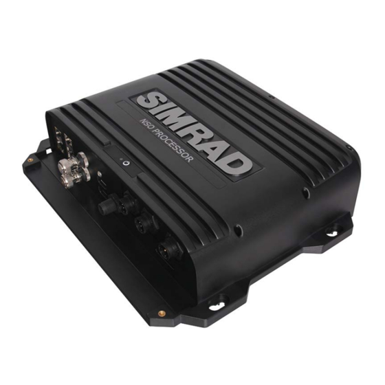
Page 6: Nso-Ii Overview
NSO-II Overview The NSO-II Marine Processor features a fast quad core processor, and dual monitor outputs to drive two displays with independant information. Connectivity options for data are broad, with an internal ethernet switch with three ports, NMEA 0183 transmit and receive ports, and a connection point for a NMEA 2000 compliant data bus. -
Page 7: Nso-Ii Marine Processor Box
NSO-II Marine Processor Box Description Ethernet Network ports with PoE (2x) Ethernet Network port (1x) Video Input BNC sockets (2x) NMEA 2000 data port NMEA 0183 & RS422 (2x) Power connector USB ports (2x) HDMI sockets (2x) SD Card slot... -
Page 8: Op40 Controller (Not Included)
(and Radar STBY if applicable) STBY AUTO : Autopilot Auto steer / Stand-By Alphanumeric keypad: Used for entering numbers and text in dialog boxes NSO-II Overview | NSO-II Installation Manual... -
Page 9: Hardware Installation
Refer to the mounting template supplied with the OP40. Installation location should be planned keeping in mind space required for the selected monitor. Ensure the OP40 is conveniently located within easy reach of helm seating or standing position. Hardware Installation | NSO-II Installation Manual... -
Page 10: Wiring
Power Control Connection (yellow wire) Planning is required how you want to be able to turn on and off the NSO-II and connected compatible devices. The yellow Power Control wire on the NSO-II power cable can either be an input that will turn on the processor when power is applied, or an output that turns on other devices when the processor is powered on. - Page 11 If the right NSO-II is set to Power Control Slave, it cannot be powered down using its own power button, but can be set to standby. If the left NSO-II (Power Control Master) is off , the right NSO-II can be turned on using its own power button, but won’t turn on any other devices.
-
Page 12: External Alarm
External alarm Blue wire on power cable: An external alarm can be connected to one or more NSO-II Processors on the network. The external alarm can be a small peizo buzzer connected directly, or a horn siren connected via a relay. -
Page 13: Connecting Displays
HDMI amplifi er or use HDMI-CAT6 adaptors. Connecting control devices The NSO-II can be controlled via the OP40 keypad, or by 1 or 2 Touch screens. If a mixed system is run, with one touch and one non-touch screen, an OP40 will also be required to control the display without touch. -
Page 14: Nmea 2000 / Simnet
The KEP monitor control is connected via USB. Each USB port relates to one of two screens on the NSO-II. Naturally USB 1 relates to HDMI 1 OUT, and USB 2 relates to HDMI 2 OUT. - Page 15 Note: Most NMEA 2000 devices can be connected directly to a Simrad SimNet backbone and SimNet devices can be connected to a NMEA 2000 network by using adapter cables. Note: Simrad devices with Micro-C NMEA 2000 connectors are fully compatible with a Sim- Net network by using a Micro-C to SimNet adapter cable.
-
Page 16: Nmea 0183 Device Connection
NMEA 0183 device connection The NSO-II has four serial ports, which are connected to via two discrete cables. Each cable has one set of connections for NMEA 0183 Receive and Transmit. Both the baud rate (up to 38,400 baud) and sentences output by the NSO-II, can be confi gured. Refer to “NMEA 0183 supported sentences”... -
Page 17: Video In
When designing a system, take in to account the ports ‘lost’ when used for linking multiple NEP-2 modules together. Video In Each NSO-II can be connected to two composite video cameras, and display video images on its displays. Both NTSC and PAL formats are supported. Note: The video images will not be shared with another unit via the network. -
Page 18: Czone Connection To Nmea 2000
Network interface bridge provides power isolation and correct termination. C-ZONE 12- 24 V DC NETWORK C-ZONE Network 1 NETWORK INTERFACE Network 2 CZONE 12 V DC Network interface bridge Simrad network power Czone network power Simrad network termination CZone network termination 16 | Wiring | NSO-II Installation Manual... -
Page 19: Software Setup
To confi gure a display as a Power Control ‘Slave’ or ‘Master’ , select ‘Power Control’ from the ‘Settings’ menu. The following Simrad products can be activated by a device set to master: NEP-2, BSM-1, BSM-2, LSS-1, LSS-2, WM-2, SonicHub, BR24/3G/4G Broadband radar, , as well as all current Simrad MFDs. - Page 20 Transducer type is used for selecting the transducer model connected to the echosounder module. In some transducers with built-in temperature sensors, the temperature reading may be inaccurate if the wrong transducer is selected from the transducer type menu. 18 | Software setup | NSO-II Installation Manual...
-
Page 21: Radar Setup
MARPA calculations. Reset device ID NSO-II only support one radar on the network. Should a radar be connected, that has been connected to a dual radar network in the past, it may not be detected by the display because it has an incorrect Device ID. -
Page 22: Video In Confi Guration
Mirror image may be applied where the camera is providing a rear view, and the user wishes to see objects as they would appear in a vehicle rearview mirror, ie, on the same side as they actually are. 20 | Software setup | NSO-II Installation Manual... -
Page 23: Serial Port Setup
To enable data output, fi rst enable the ‘Serial output’ option, and then select which sentences the NSO-II needs to transmit to other devices from the ‘Serial output sentences’ list. Only a select list of the most commonly used sentences are enabled by default. -
Page 24: Nmea 2000 / Simnet Setup
In order to enable group selection, the display must be set to ‘Default’ group. In some cases it may be desired that an NSO-II on a network receives the same type of data, but from diff erent sources to that of the rest of the network devices. To do this set the data... -
Page 25: Ethernet Setup
The upper table gives an account of the various automatically synchronised databases that ensure Simrad display units (NSO-II, NSS, NSE plus B&G Zeus, and Zeus Touch) are all using the same user settings and data. Each unit stores the database locally, so that all information is available if the device is run in standalone. - Page 26 The network LED on modules such as NEP-2, BSM-1, and RI10, can be useful for determining if the network is fundamentally operational. No light indicates no connection. A rapidly blinking green LED means the network module is communicating with another device. 24 | Software setup | NSO-II Installation Manual...
-
Page 27: Wifi Setup
GoFree module. If the module is installed out of easy access, see the following section ‘Access Points’ on how to identify the ‘Network Key’ (password) from the NSO-II. The above dialogue will appear on the NSO-II display when connection is attempted. Select ‘Yes’... - Page 28 DHCP servers. To make it easy to fi nd DHCP servers on a network, dhcp_probe may be run from the NSO-II, which will show results similar to the following when another dhcp server is found;...
-
Page 29: Autopilot Setup
NSO-II unit. If you connect the NSO-II to an already commissioned autopilot system, you only have to do an automatic source selection as described above before the autopilot is ready to be used. - Page 30 Find the lowest possible value that will prevent the rudder from continuous hunting. A wide deadband will cause inaccurate steering. Note: The rudder deadband setting is not available when the autopilot is confi gured for Virtual Rudder Feedback. 28 | Software setup | NSO-II Installation Manual...
- Page 31 (local) fi eld angle will guide you to the local interfering magnetic object. Note: Calibration must be made on the compass that is active for the autopilot. If the compass is not possible to initiate calibration from the device list on the NSO-II, refer to the compass’ own instructions regarding calibration. Note: In certain areas and at high latitudes the local magnetic interference becomes more signifi...
- Page 32 10kn Transition speed set to 9kn Transition to HI parameters with decreasing speed: 8kn Active response parameter set is shown in the autopilot popup, and the following abbreviations are used: 30 | Software setup | NSO-II Installation Manual...
- Page 33 (or close to), while steering to apparent wind is used when beating or reaching. Apparent wind steering is preferred when you want to maintain maximum boat speed without continuous trimming of the sails. | 31 Software setup | NSO-II Installation Manual...
- Page 34 20 seconds. Rate limit Sets the maximum allowed rate of turn. The value should be kept at 6.0°/second unless there is a need for more rapid response in turns. 32 | Software setup | NSO-II Installation Manual...
-
Page 35: Czone Setup
CZone Confi guration Tool, a specialised PC application available from BEP Marine Ltd, and associated CZone distributors. The NSO-II system provides a means to load the Confi g fi le, as well as apply updates to module fi rmware, removing the need to take a laptop computer aboard the vessel. - Page 36 Setting CZone to display at startup With this option selected, the CZone control page will be shown fi rst, every time the NSO-II is powered up. CZone backlight control Enabling this will cause the NSO-II to synchronize its backlight setting with that of any CZone Display Interfaces set up to share backlight settings.
-
Page 37: Software Updates And Screen Calibration
Later, if the NSO-II is defaulted or user data is accidentally deleted, simply return to the fi les page, highlight the backed up fi le, and select ‘Import’ . View fi le details for creation date. -
Page 38: Accessory Cables
Ethernet cable yellow 5 Pin 2 m (6.5 ft) 000-0127-29 Ethernet cable yellow 5 Pin 4.5 m (15 ft) 000-0127-30 Ethernet cable yellow 5 Pin 7.7 m (25 ft) 000-0127-37 Ethernet cable yellow 5 Pin 15.2 m (50 ft) 36 | Accessory cables | NSO-II Installation Manual... -
Page 39: Supported Data
Time & Date 129038 AIS Class A Position Report 129039 AIS Class B Position Report 129040 AIS Class B Extended Position Report 129283 Cross Track Error 129284 Navigation Data 129539 GNSS DOPs | 37 Supported data | NSO-II Installation Manual... - Page 40 Suzuki Engine and Storage Device Confi g 130832 Fuel Used - High Reolution 130834 Engine and Tank Confi guration 130835 SetEngineAndTankConfi guration 130838 Fluid Level Warning 130839 Pressure Insect Confi guration 130843 Sonar Status, Frequency and DSP Voltage 38 | Supported data | NSO-II Installation Manual...
- Page 41 SetEngineAndTankConfi guration 130836 Fluid Level Insect Confi guration 130837 Fuel Flow Turbine Confi guration 130839 Pressure Insect Confi guration 130845 Weather and Fish Prediction and Barometric Pressure History 130850 Evinrude Engine Warnings | 39 Supported data | NSO-II Installation Manual...
-
Page 42: Nmea 0183 Supported Sentences
Receive Transmit Echo Receive Transmit Compass Receive Transmit Wind Receive Transmit AIS / DSC Receive AIS sentences are not bridged to or from NMEA 2000. MARPA Transmit These are only output sentences 40 | Supported data | NSO-II Installation Manual... -
Page 43: Specifi Cations
NMEA 0183 port baud rate 4800, 9600, 19200, & 38400 (via proprietary cable) RS422 port baud rate 1200, 2400, 4800, 9600, 19200, 38400, 57600, 115200 Charting support Navionics and CMap on SD card | 41 Specifi cations | NSO-II Installation Manual... -
Page 44: Dimensioned Drawings
Dimensioned drawings 281 mm (11.05”) 66 mm (2.58”) 265 mm (10.42”) 42 | Dimensioned drawings | NSO-II Installation Manual...
Need help?
Do you have a question about the NSO-II and is the answer not in the manual?
Questions and answers