Table of Contents
Advertisement
Quick Links
Advertisement
Table of Contents

Related Manuals for Simrad FU80


Summary of Contents for Simrad FU80
- Page 1 FU80, NF80, QS80 User Guide ENGLISH...
- Page 2 This manual represents the product as at the time of printing. Navico Holding AS and its subsidiaries, branches and affiliates reserve the right to make changes to specifications without notice. Compliance statements Simrad FU80, NF80 and QS80: • meet the technical standards in accordance with Part 15.103 of the FCC rules •...
-
Page 3: Table Of Contents
Basic operation - all remotes Using the NF80 Using the FU80 Using the QS80 Changing commanded rudder direction Alerts Restoring factory settings Maintenance Changing default settings The main menu Specifications Technical specifications Drawings Contents | FU80, NF80, QS80 User Guide... -
Page 4: Introduction
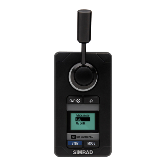
Introduction About this manual This manual describes how to install and use the FU80, NF80 and the QS80 remotes. NF80 FU80 QS80 These remotes can be used to remotely control autopilot systems. They can also be used to remotely operate the autopilot function in a Simrad MFD (Multifunction Display). -
Page 5: Parts Included
Description Remote unit, including 6 m (19.7 ft) Micro-C drop cable Bezel Bag including: - Gasket for panel sealing - Mounting accessories Long type lever (FU80 and NF80) Micro-C T-connector User manual Mounting template Warranty card Introduction | FU80, NF80, QS80 User Guide... -
Page 6: Installation
Peel backing off the gasket (A) and apply it to the remote or to the mounting surface Place the remote into the console Secure the unit with the 4 screws (B) Clip the bezel (C) in place. Installation | FU80, NF80, QS80 User Guide... - Page 7 (D) Secure the unit with the 4 screws (B) Clip the bezel (C) in place. The NF80 lever The lever is not mounted from factory. Screw the lever firmly into the mounting hole. Installation | FU80, NF80, QS80 User Guide...
-
Page 8: Wiring
If required, make drip and service loops. The remotes connect to the CAN bus backbone or SimNet backbone as shown below. For part AP60/AP70/AP80 system AP24/AP28/NSE/NSS/NSO systems numbers, refer to our website. Installation | FU80, NF80, QS80 User Guide... -
Page 9: Configuring
If the remotes are installed in a system with an AC12/AC12N or an AC42/AC42N computer, the Alarms and Sources SimNet groups must be changed from default value (100) to 1. Note that the value defaults to 100 also after a reset. 10 | Installation | FU80, NF80, QS80 User Guide... -
Page 10: Operation
Softkey Function OK/Accept STBY MODE STBY MODE Cancel/Return to previous menu level Mute alert STBY MODE Move upwards in menu STBY MODE Move downwards in menu STBY MODE | 11 Operation | FU80, NF80, QS80 User Guide... - Page 11 Active thrusters are indicated with thruster Thruster icon on the display Screen alive indicator - black square moving Alive up/down in the top left corner of the screen 12 | Operation | FU80, NF80, QS80 User Guide...
- Page 12 Active thrusters are indicated with thruster icon on the display. ¼ Note: Only available in AP60, AP70 and AP80 systems. The thrusters must be available for autopilot steering in active steering profile. | 13 Operation | FU80, NF80, QS80 User Guide...
-
Page 13: Using The Nf80
If the mode is available on other autopilot systems, the mode can only be used if the system is set up for sailboat. See the Installation manual for your system. 14 | Operation | FU80, NF80, QS80 User Guide... - Page 14 NoDrift mode. The value will change 1° each time the lever is pressed to left or right. If you keep the lever pressed, the value automatically changes at a rate of 5° per second. Each beep indicates a 1° change. | 15 Operation | FU80, NF80, QS80 User Guide...
-
Page 15: Using The Fu80
Default mode selection ¼ Note: It is not possible to use FU80 with an AP24/28 operating on VRF (Virtual Rudder Feedback). You toggle between available modes by repeatedly pressing the MODE key. The selection times out and triggers a mode shift. - Page 16 They are located in Local Settings on an FU80, and does not affect the rest of the system (other than the mentioned behavior - see below). With multiple FU80 units in a system, the units are configured independently from each other.
- Page 17 Follow-Up on Command This feature makes it possible to switch the autopilot system to FU mode by a single press on the take command button on the FU80. Follow-up steering In FU mode you use the lever to set the commanded rudder angle.
-
Page 18: Using The Qs80
Centering the rudder A single downwards press on the stick while in Standby or NFU mode will command the rudder to mid-position. A short beep will sound when the rudder is centered. | 19 Operation | FU80, NF80, QS80 User Guide... - Page 19 1° each time the stick is pressed to left or right. If you keep the stick pressed, the value automatically changes at a rate of 5° per second. Each beep indicates a 1° heading/course change. 20 | Operation | FU80, NF80, QS80 User Guide...
-
Page 20: Changing Commanded Rudder Direction
FU80 and NF80. When you press the lever to port, the rudder is directed to port. If the lever is rotated 180° on an FU80, or if an FU80 or NF80 is mounted facing aft, the rudder movement can be inverted to maintain a rudder command that coincide with the lever movement. -
Page 21: Restoring Factory Settings
If the unit requires any form of cleaning, use fresh water and a mild soap solution (not a detergent). It is important to avoid using chemical cleaners and hydrocarbons such as diesel, petrol, etc. 22 | Operation | FU80, NF80, QS80 User Guide... -
Page 22: Changing Default Settings
Units Contrast Damping Station Alarms Sources *) Only available on FU80 and NF80. **) Only available on FU80. • Local settings: Gives access to settings that applies to this unit • SimNet group: Assigns this unit to a SimNet group You remove the menu and return to standard display by pressing and holding the STBY key, or by moving the lever/stick. -
Page 23: Specifications
Back: Plastic cover Temperature -25° C to + 55° C (-13° F to +131° F) Weight NF80, FU80: 0.5 kg (1.10 lbs) QS80: 0.4 kg (0.88 lbs) Environmental Weather IEC 60945 sec. 8.8, exposed, front when desk mounted or bulkhead mounted with optional frame. -
Page 24: Drawings
Drawings Dimension, Remotes 66 mm (2.60") 40 mm (1.55") 80 mm (3.15") 66 mm (2.60") NF80 QS80 FU80 51 mm (1.98") 63 mm (2.46") 16 mm (0.63") 63 mm (2.46") | 25 Specifications | FU80, NF80, QS80 User Guide... - Page 25 40 mm (1.55") 80 mm (3.15") 66 mm (2.60") Connector pin-out Color Function Shield NET-S (Power source +) Black NET-C (Power source -) White NET-H (CAN high) Blue NET-L (CAN low) 26 | Specifications | FU80, NF80, QS80 User Guide...
Need help?
Do you have a question about the FU80 and is the answer not in the manual?
Questions and answers