
Related Manuals for Samsung CHB5707L/5237L


Summary of Contents for Samsung CHB5707L/5237L
-
Page 1: Table Of Contents
COLOR MONITOR CHB5707L/5237L CHB6107L(M)/6117L(M) CHB7707L(M)/7227L(M)/7727L(M) SERVICE Manual COLOR MONITOR CONTENTS 1. Precautions 2. Reference Information 3. Product Specifications 4. Operating Instructions 5. Disassembly & Reassembly 6. Alignment & Adjustments 7. Troubleshooting 8. Exploded View & Parts List 9. Electrical Parts List MENU 10. - Page 2 Samsung Electronics Co., Ltd. September 1998 Printed in Korea Code No.: BH68-61129A...
-
Page 3: Precautions
1 Precautio 1-1 Safety Precautions WARNINGS Inspect all protective devices such as nonmetallic For continued safety, do not attempt to modify the control knobs, insulating materials, cabinet backs, circuit board. adjustment and compartment covers or shields, isolation resistor-capacitor networks, mechanical Disconnect the AC power before servicing. -
Page 4: Servicing Precautions
1 Precautions 1-2 Servicing Precautions WARNING1: First read the “Safety Precautions” section of this manual. If unforeseen circumstances create conflict between the servicing precautions and safety precautions, always follow the safety precautions. WARNING2: A high voltage VR replaced in the wrong direction may cause excessive X-ray emissions. -
Page 5: Reference Information
2 Reference Information 2-1 List of Abbreviations, Symbols and Acronyms 2-1-1 Abbreviations Abbreviation Definition Abbreviation Definition ASS’Y Assembly Oscillator Blue C-Polyester B+ ADJ B+ Adjustment PARA Parabola B-CUT Blue-Cutoff PARALL Parallelogram B-GAIN Blue Gain PIN-BAL Pincushion Balance BRIGHT Brightness PRE-AMP Pre-Amplifier R-Composition Power Saving1 (suspend) - Page 6 2 Reference Information 2-1-2 Symbols Can emit X-radiation Hot Ground Cold Ground Electrostatically Sensitive Device (ESD) Provides special safety considerations 2-1-2 Acronyms Acronym Definition Acronym Definition Automatic Brightness Limits Horizontal/Vertical High Voltage Alternating Current Automatic Contrast Limit Input/Output Automatic Frequency Control Integrated Circuit ANSI American National Standards Institute...
-
Page 7: Product Specifications
3 Product Specifications 3-1 Specifications Item Description Picture Tube: 15-Inch (38 cm): 13.8-inch (35 cm) viewable, 16-Inch (40 cm): 15.0-inch (38 cm) viewable, 17-Inch (43 cm): 15.7-inch (39.80 cm) viewable, Full-square flat-face tube, 90˚ Deflection, 0.28 mm Dot pitch, Semi- tint, Non-glare, Invar shadow mask, Anti-static silica coating Conventional type (16”), AK Shadow mask (16”) Scanning Frequency Horizontal : 30 kHz to 70 kHz (Automatic) -
Page 8: Pin Assignments
3 Product Specifications 3-2 Pin Assignments Sync 15-Pin Signal Cable Connector (Figure 3-1) Cable Adapter (Figure 3-2) Type Macintosh Separate Pin No. GND-R Green Blue H/V Sync Sense 0 DDC Return Green GND-R GND-G GND-G Sense 1 GND-B Reserved Reserved Blue GND-Sync/Self-raster Sense 2... -
Page 9: Timing Chart
3 Product Specifications 3-3 Timing Chart This section of the service manual describes the timing that the computer industry recognizes as standard for computer-generated video signals. Table 3-1. Timing Chart Mode VESA VGA2/70 Hz VGA3/60 Hz 640/75 Hz 640/85 Hz 800/75 Hz 800/85 Hz 1024/75 Hz... - Page 10 3 Product Specifications Memo CHB5**7L/6**7L/7**7L...
-
Page 11: Operating Instructions
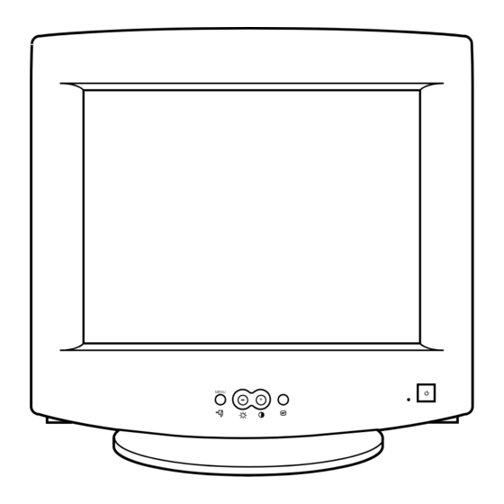
4 Operating Instructions 4-1 Front View and Control 4-1-1 Front View MENU Signal Cable Power Port Figure 4-2. Rear View MENU Table 4-1. Front Panel Controls Location Symbol Description Power Button Power Indicator LED (Dual Color) Figure 4-1. Front Control Panel MENU Menu Display &... - Page 12 4 Operating Instructions Note 1: This monitor requires a cable adapter for use with a Macintosh computer. The MacMaster Cable Adapter supports all monitors and all Macintosh, Centris, Quadra, Duo Dock, and Power Macintosh computers. If you do not already have a cable adapter, check with your computer dealer.
-
Page 13: Disassembly And Reassembly
5 Disassembly and Reassembly This section of the service manual describes the disassembly and reassembly procedures for the CHB5**7L/6**7L/7**7L monitors. WARNING: This monitor contains electrostatically sensitive devices. Use caution when handling these components. 5-1 Disassembly (CHB7**7L/CHB6**7L) Cautions:1. Disconnect the monitor from the power source before disassembly. 2. - Page 14 5 Disassembly and Reassembly 5-2 Disassembly (CHB5**7L) Cautions:1. Disconnect the monitor from the power source before disassembly. 2. Follow these directions carefully; never use metal instruments to pry apart the cabinet. 5-2-1 Cabinet Disassembly 5-2-3 Removing the Main PCB 1. With a pad beneath it, stand the monitor on its 1.
-
Page 15: Alignment And Adjustments
Computer with a video board that uses the interfere with monitor performance. ET-4000 chipset (strongly recommended if using Samsung DM 200 software) and that Use an external degaussing coil to limit magnetic displays: 1024 x 768 @ 85 Hz, or 800 x 600 build up on the monitor. - Page 16 6 Alignment and Adjustments 6-1-3 Connecting the SoftJig 6-1-4 After Making Adjustments Connect the monitor to the signal generator and/ After finishing all adjustments, test the monitor in or PC as illustrated in Figures 6-1 and 6-2. all directions. If, for example, the monitor does not Note: The signal cable connector which includes meet adjustment specifications when facing north, the 3-wire cable must connect to the...
-
Page 17: Display Control Adjustments
6 Alignment and Adjustments 6-2 Display Control Adjustments 6-2-1 Centering 6-2-1 (c) HORIZONTAL POSITION ADJUSTMENT Centering means to position the center point of CONDITIONS the display in the middle of the display area. Scanning frequency: 68 kHz/85 Hz (17Ó/16Ó) Horizontal size and position and vertical size and 54 kHz/85 Hz (15Ó) position control the centering of the display. - Page 18 6 Alignment and Adjustments 6-2-2 (a) HORIZONTAL LINEARITY ADJUSTMENT 6-2-4 Pinbalance Adjustment CONDITIONS CONDITIONS Scanning frequency: 68 kHz/85 Hz (17Ó/16Ó) Scanning frequency: 68 kHz/85 Hz (17Ó/16Ó) 54 kHz/85 Hz (15Ó) 54 kHz/85 Hz (15Ó) Display image: Crosshatch pattern Display image: Crosshatch pattern Brightness: Maximum...
- Page 19 6 Alignment and Adjustments 6-2-6 Side Pincushion Adjustment 6-2-7 Tilt Adjustment CONDITIONS CONDITIONS Scanning frequency: 68 kHz/85 Hz (17Ó/16Ó) Scanning Frequency: 68 kHz/85 Hz (17Ó/16Ó) 54 kHz/85 Hz (15Ó) 54 kHz/85 Hz (15Ó) Display image: Crosshatch pattern Display image: Crosshatch pattern Brightness: Maximum Increase or decrease BARREL to straighten the...
-
Page 20: Color Adjustments
6 Alignment and Adjustments 6-3 Color Adjustments 6-3-1 Color Coordinates (Temperature) 6-3-2 (b) G-GAIN ADJUSTMENT Color temperature is a measurement of the 1/3H-1/2H radiant energy transmitted by a color. For FRONT BEZEL OPENING computer monitors, the color temperature refers to the radiant energy transmitted by white. Color BACK RASTER 1/3V-1/2V coordinates are the X and Y coordinates on the... - Page 21 6 Alignment and Adjustments 1. Increase or decrease R_GAIN and B_GAIN to 6-3-3 Color Adjustments for 6500K make the video white. 6-3-3 (a) BACK RASTER COLOR ADJUSTMENT (For 9300K color adjustment: x = 0.283 ± 0.02, y = 0.298 ± 0.02.) CONDITIONS Scanning frequency: 68 kHz/85 Hz (17Ó/16Ó)
- Page 22 6 Alignment and Adjustments 6-3-4 Luminance Uniformity Check CONDITIONS Orientation: Monitor facing east Luminance is considered uniform only if the ratio Scanning frequency: 68 kHz/85 Hz (17Ó/16Ó) of lowest to highest brightness areas on the screen 54 kHz/85 Hz (15Ó) is not less than 7.5:10.
- Page 23 CONDITIONS Direction: Monitor facing east Warm-up: 30 minutes Display image: Crosshatch pattern Samsung SDD CRT Tolerances: See Table 6-4 1 Setup Bolt 2 Bow Magnet 3 Band 4 2-Pole Magnet PROCEDURE...
- Page 24 6 Alignment and Adjustments 5. After completing the red and blue center 1. Make sure the display is not affected by convergence adjustment, locate the pair of external magnetic fields. 6-pole magnet rings. 2. Make sure the static convergence is properly 6.
- Page 25 6 Alignment and Adjustments 6-4-3 Bow Convergence Adjustments 6-4-4 (a) HORIZONTAL LINE RED AND BLUE BALANCE CONVERGENCE CONDITIONS Orientation: Monitor facing east. BLUE Display Image: Crosshatch pattern with mixed RGB colors. Required tools: Flat-head (Ð) screwdriver, 1.5 mm Philips (+) screwdriver, 1.5 mm Hexkey, 2.5 mm Figure 6-17.
- Page 26 6 Alignment and Adjustments Memo 6-12 CHB5**7L/6**7L/7**7L...
-
Page 27: Troubleshooting
7 Troubleshooting 7-1 Parts Level Troubleshooting Notes: 1. If a picture does not appear, fully rotate the brightness and contrast controls clockwise and reinspect. 2. Check the following circuits. • No raster appears: Power circuit, Horizontal output circuit, H/V control circuit, and H/V output circuit. •... -
Page 28: Dpms Failure
7 Troubleshooting 7-1-2 DPMS Failure WAVEFORMS Check signal source H/V sync video level. 544 V (IC601, #1) Make No H/V sync (power off mode) CH1 P-P = 544 V CH1 RMS = 332.4 V LED blinks Check IC201 Pin 20. +12 V line off Check IC201 Pin 41. - Page 29 7 Troubleshooting 7-1-3 H_Deflection Failure Does PWM output signal appear Does DC 5 V appear at Check 5 V, 12 V line. at Pin 26 (H_out) of IC401? Pin 32 of IC401? WAVEFORMS Check IC401. 8.80 V (IC401, #26) Does 12 Vp-p signal appear at Check Q441 and Q442.
- Page 30 7 Troubleshooting 7-1-5 H_Lin. Failure IC201 Pin 33 voltage varies with Replace IC201. different H_Lin. DAC values? IC302 Pin 14 voltage varies with Check +12 V, –10 V line. different H_Lin. DAC values? Check some parts around IC302. Check Q471, Q472, T403. 7-1-6 Invariable H_Size IC401 Pin 28 voltage varies with Check and replace IC401.
- Page 31 7 Troubleshooting 7-1-8 Side Pin or Trap Failure WAVEFORMS IC401 Pin 24 output exists? Check and replace IC401. 720 mV (IC401, #24) Check some parts around IC401 Pins 15 and 16. CH1 P-P = 720 mV CH1 RMS = 2.792 V 7-1-9 Para.
- Page 32 7 Troubleshooting 7-1-11 V Deflection Failure WAVEFORMS 13 V, –10 V line is on? Refer to 7-1-1 No Power Supply 3.40 V (IC401, #23) IC401 Pin 23 output exists? Check and replace IC401. CH1 P-P = 3.40 V CH1 RMS = 3.756 V 46.4 V (IC301, #5) Check and replace some parts IC301 Pin 5 output exists?
-
Page 33: High Voltage Failure
7 Troubleshooting 7-1-13 High Voltage Failure WAVEFORMS Check and replace IC501 IC501 Pin 5 OSC pulse exists? 12.16 V (IC501, #5) and +12 V line. Check and replace Q509, Q501 and Q502 Gate driving pulse exists? D504. CH1 P-P = 12.16 V CH1 RMS = 6.376 V 9.12 V (Q502, Gate) Check and replace Q503,... - Page 34 7 Troubleshooting 7-1-15 Dynamic Focus Failure WAVEFORMS IC401 Pin 10 output is right? Replace the IC401. 720 mV (IC401, #10) Some parts around Q551 are right? Replace failed part. CH1 P-P = 720 mV CH1 RMS = 2.710 V 50.8 V (T502, #6) T502 Pin 6 input is right? Check and replace C556.
-
Page 35: No Video
7 Troubleshooting 7-1-16 No Video WAVEFORMS Check signal cable and connection. 780 mV (IC101, #5, 8, 10) IC101 Pins 5, 8 and 10 inputs Check the signal cable connection. are right? CH1 P-P = 780 mV CH1 RMS = 2.494 V 2.72 V (IC101, #21,24,26) IC101 Pins 21, 24 and 26 Check I... -
Page 36: Micom Failure
7 Troubleshooting 7-1-17 Micom Failure WAVEFORMS IC201 Pin 5 input is right? Check IC604. 5.00 V (IC201, #6, 7) IC201 Pins 6 and 7 inputs Check X201, C206 and C207. are right? CH1 P-P = 5.00 V CH1 RMS = 2.966 V IC201 Pin 2 input is right? Check IC202. - Page 37 7 Troubleshooting 7-1-18 OSD Failure WAVEFORMS Check CN104 and connector Ass’y. 4.92 V (IC104, #10) Check and replace Q103. IC104 Pin 10 input is right? Check CN104 Pin 15. CH1 P-P = 4.92 V CH1 RMS = 5.072 V 4.84 V (IC104, #5) Check and replace Q102.
- Page 38 7 Troubleshooting 7-1-19 User Control Failure Does the DC level change at Check the button. Pins 38 and 39 of IC201 when you (SW201 ~ SW203) push the push button S/W? Check IC201. 7-1-20 Degaussing Failure Check degaussing connector. RL601 operation is right? Check D-coil and TH601.
-
Page 39: General Troubleshooting
7 Troubleshooting 7-2 General Troubleshooting 7-2-1 No Picture LED blinks? Refer to 7-2-2 Shut down. LED is green color? Check Micom. Check G2 voltage, high voltage, R, G, B cathode voltage. 7-2-2 Shut Down Blinking LED’s? Check power supply. Check horizontal, vertical deflection Scan failure system and check power supply secondary voltages. -
Page 40: Missing Color
7 Troubleshooting 7-2-3 Missing Color Are proper Video levels on CN101 (D-Sub) Pins 1, 3 and 5, Check signal generator and cathode. R-BNC, G-BNC and B-BNC? Are proper AC voltage on all Refer to 7-1-16 No Video. cathodes? Check IC101 Pins 15, 16 and 17. Are proper DC voltage on all Check QR01, QR02, QG01, QG02, cathodes? - Page 41 7 Troubleshooting 7-2-4 Visible Retrace Check white balance adjustment. Is G2 voltage right? Check G2 control volume and FBT. Is blank pulse on Pin 19 of IC101 Check Q102, CN104 and T402 Pin 10. on Video board? Is blank pedestal on Check IC101 and related components.
-
Page 42: Unsynchronized Image
7 Troubleshooting 7-2-5 Unsynchronized Image Check input signals Pins 9 and 11 of CN101. Are signals right? Check Video cable. Signals at Pins 3 and 4 of Check ZD103 and D106 on CN104 are right? Video board. Signals at CN102A Pins 3 and 6 Check Video and Main board. - Page 43 7 Troubleshooting 7-2-6 Misconvergence Try readjusting convergence. Is the convergence now Done within spec? Readjust convergence. Is the convergence now Done within spec? Change CRT and readjust convergence. Done CHB5**7L/6**7L/7**7L 7-17...
-
Page 44: Purity Failure
7 Troubleshooting 7-2-7 Poor Focus Adjust focus VR. Aging monitor and check for focus Improved focus? change. Check focus leads from FBT to CRT Socket. Check the CRT Socket. Refer to 7-1-15 Dynamic Is dynamic focus circuit right? Focus Failure. Replace the CRT and verify focus. -
Page 45: Electrical Parts List
9 Electrical Parts List 9-1 Main PCB Parts Loc. No. Coordinates (X,Y) Code No. Description Specification Remarks BD311 23.7 140.0 3301-000011 MAG-CORE,FERRITE,BEAD 1.2UH,3.5_5.7MM,10 OHM BD312 40.4 122.7 3301-000011 MAG-CORE,FERRITE,BEAD 1.2UH,3.5_5.7MM,10 OHM BD401 50.9 105.5 3301-000011 MAG-CORE,FERRITE,BEAD 1.2UH,3.5_5.7MM,10 OHM BD402 74.7 139.8 3301-000011 MAG-CORE,FERRITE,BEAD... - Page 46 9 Electrical Parts List Loc. No. Coordinates (X,Y) Code No. Description Specification Remarks C406 52.9 173.8 2401-000027 C-AL 4.7uF,20%,50V,GP,5mm,TP C407 43.9 163.6 2305-000280 C-FILM,MPEF 220nF,10%,63V,7.5x13.5mm,5mm,T C408 42.8 169.6 2401-000031 C-AL 47uF,20%,16V,GP,5mm,TP C409 38.7 160.0 2202-002009 C-CERAMIC,MLC-AXIAL 100nF,+80-20%,50V,Y5V,2.3X3.0 C410 32.2 149.7 2401-000050 C-AL 10uF,20%,16V,GP,5x11mm,2mm,TP...
- Page 47 9 Electrical Parts List Loc. No. Coordinates (X,Y) Code No. Description Specification Remarks C507 155.7 134.5 2401-000053 C-AL 10uF,20%,25V,GP,5mm,TP C508 159.8 137.0 2401-001556 C-AL 47uF,20%,35V,GP,8x11.5mm,5mm,T C509 160.6 134.5 2202-002008 C-CERAMIC,MLC-AXIAL 10nF,+80-20%,50V,Y5V,2.3X3.0 C510 59.8 24.8 2401-000027 C-AL 4.7uF,20%,50V,GP,5mm,TP C511 123.4 145.2 2401-000031 C-AL 47uF,20%,16V,GP,5mm,TP...
- Page 48 9 Electrical Parts List Loc. No. Coordinates (X,Y) Code No. Description Specification Remarks C623_M 167.9 98.8 2401-000151 C-AL 1000uF,20%,25V,GP,12.5x20mm,5m M/MEDIA C624 142.3 67.1 2401-000142 C-AL 1000uF,20%,16V,WT,10x20mm,5mm C625 133.9 39.5 2201-000469 C-CERAMIC,DISC 330pF,10%,500V,Y5P,6x3.5,5,TP C626 148.3 14.6 2301-000012 C-FILM,PEF 2.2nF,5%,100V,10.5x12.5x6.5,5m C627 130.5 23.2 2301-000287 C-FILM,PEF...
- Page 49 9 Electrical Parts List Loc. No. Coordinates (X,Y) Code No. Description Specification Remarks D507 181.2 131.4 0401-000005 DIODE-SIG 1N4148,DO-35,75V,150MA,1V,10MA D508 266.8 166.5 0402-001114 DIODE-RECTIFIER 1N4936GP,400V,1A,DO-204AL,TP 17”/16” D509 269.5 160.0 0401-000006 DIODE-SWITCHING BAV21,200V,250mA,400mW,50nS,DO D511 272.9 216.4 0402-001114 DIODE-RECTIFIER 1N4936GP,400V,1A,DO-204AL,TP D513 270.2 239.0 0401-000006 DIODE-SWITCHING...
- Page 50 9 Electrical Parts List Loc. No. Coordinates (X,Y) Code No. Description Specification Remarks 244.6 237.6 BH39-40305U JUMPER JUMPER WIRE 244.6 240.1 BH39-40305U JUMPER JUMPER WIRE 17”/16” 88.9 190.8 BH39-40305U JUMPER JUMPER WIRE 90.2 186.8 BH39-40305U JUMPER JUMPER WIRE 244.6 230.1 BH39-40305U JUMPER JUMPER WIRE...
- Page 51 9 Electrical Parts List Loc. No. Coordinates (X,Y) Code No. Description Specification Remarks JP52 73.8 132.7 BH39-40305U JUMPER JUMPER WIRE JP53 79.4 154.4 BH39-40305U JUMPER JUMPER WIRE JP54 88.5 130.2 BH39-40305U JUMPER JUMPER WIRE JP55 90.6 122.4 BH39-40305U JUMPER JUMPER WIRE JP56 106.5 122.3...
- Page 52 9 Electrical Parts List Loc. No. Coordinates (X,Y) Code No. Description Specification Remarks JP101 43.2 118.9 BH39-40305U JUMPER JUMPER WIRE JP102 82.2 69.8 BH39-40305U JUMPER JUMPER WIRE JP103 103.4 62.0 BH39-40305U JUMPER JUMPER WIRE JP105 223.7 64.1 BH39-40305U JUMPER JUMPER WIRE JP106 74.2 54.7...
- Page 53 9 Electrical Parts List Loc. No. Coordinates (X,Y) Code No. Description Specification Remarks Q501 141.3 154.0 0501-000303 TR-SMALL SIGNAL KSA733,PNP,TO-92,EBC Q502 212.7 138.5 0505-001181 FET-SILICON IRF634A,N,250V,8.1A,450mohm,74 Q503 270.0 126.6 0501-000122 TR-SMALL SIGNAL 2N3904,NPN,TO-92,EBC Q504 254.3 146.5 0505-001206 FET-SILICON SSS6N90A,N,900V,24A,2.3ohm,50W Q506 289.6 170.0 0501-000303...
- Page 54 9 Electrical Parts List Loc. No. Coordinates (X,Y) Code No. Description Specification Remarks R247 60.3 40.8 2001-000040 R-CARBON 470ohm,5%,1/6W,AA,TP,1.8x3.2m R248 79.4 79.7 2001-000868 R-CARBON 56ohm,5%,1/6W,AA,TP,1.8x3.2mm R249 34.5 81.6 2001-000069 R-CARBON 12Kohm,5%,1/6W,AA,TP,1.8x3.2mm 17”/16” 2001-000889 R-CARBON 6.8Kohm,5%,1/6W,AA,TP,1.8x3.2mm 15” R250 66.2 30.8 2001-000868 R-CARBON 56ohm,5%,1/6W,AA,TP,1.8x3.2mm R301...
- Page 55 9 Electrical Parts List Loc. No. Coordinates (X,Y) Code No. Description Specification Remarks 2001-000075 R-CARBON 39Kohm,5%,1/6W,AA,TP,1.8x3.2mm 16” 2001-000079 R-CARBON 56Kohm,5%,1/6W,AA,TP,1.8x3.2mm 15” R415 61.9 162.6 2001-000056 R-CARBON 4.7Kohm,5%,1/6W,AA,TP,1.8x3.2mm 2001-000976 R-CARBON 8.2Kohm,5%,1/6W,AA,TP,1.8x3.2mm 16” R416 15.4 169.5 2001-000082 R-CARBON 68Kohm,5%,1/6W,AA,TP,1.8x3.2mm 17” 2001-000562 R-CARBON 27Kohm,5%,1/6W,AA,TP,1.8x3.2mm 16”...
- Page 56 9 Electrical Parts List Loc. No. Coordinates (X,Y) Code No. Description Specification Remarks R466 39.2 201.6 2001-000043 R-CARBON 1Kohm,5%,1/6W,AA,TP,1.8x3.2m R467 149.4 233.7 2003-000767 R-METAL OXIDE(S) 680ohm,5%,2W,AA,TP,4x12mm R471 96.5 132.1 2001-000069 R-CARBON 12Kohm,5%,1/6W,AA,TP,1.8x3.2mm R472 100.5 170.4 2001-000108 R-CARBON 18Kohm,5%,1/6W,AA,TP,1.8x3.2mm R473 93.9 173.2 2003-000349 R-METAL OXIDE...
- Page 57 9 Electrical Parts List Loc. No. Coordinates (X,Y) Code No. Description Specification Remarks R542 94.4 161.6 2004-001040 R-METAL 50Kohm,1%,1/4W,AA,TP,2.4x6.4mm 17”/16” 2004-004145 R-METAL 52Kohm,1%,1/4W,AA,TP,2.4x6.4mm 15” R543 101.8 133.1 2001-000077 R-CARBON 47Kohm,5%,1/6W,AA,TP,1.8x3.2mm R544 93.9 133.1 2001-000074 R-CARBON 33Kohm,5%,1/6W,AA,TP,1.8x3.2mm R545 110.5 124.4 2001-000562 R-CARBON 27Kohm,5%,1/6W,AA,TP,1.8x3.2mm R546...
- Page 58 9 Electrical Parts List Loc. No. Coordinates (X,Y) Code No. Description Specification Remarks R637_M 299.6 102.9 2001-000043 R-CARBON 1Kohm,5%,1/6W,AA,TP,1.8x3.2m M/MEDIA R638_M 312.8 84.1 2001-000043 R-CARBON 1Kohm,5%,1/6W,AA,TP,1.8x3.2m M/MEDIA R639_M 306.2 102.9 2001-000067 R-CARBON 10Kohm,5%,1/6W,AA,TP,1.8x3.2m M/MEDIA RL601 285.0 82.9 3501-001111 RELAY-POWER 12Vdc,250mW,5A,1FormA,15mS,5mS SK501 241.5 220.7...
- Page 59 9 Electrical Parts List 9-2 Video PCB Parts Loc. No. Coordinates (X,Y) Code No. Description Specification Remarks C101 46.4 90.9 2401-000037 C-AL 470uF,20%,16V,GP,8x11.5mm,5mm C102 30.7 61.5 2202-002009 C-CERAMIC,MLC-AXIAL 100nF,+80-20%,50V,Y5V,2.3X3.0 C103 2202-002009 C-CERAMIC,MLC-AXIAL 100nF,+80-20%,50V,Y5V,2.3X3.0 C104 91.6 16.3 2401-000010 C-AL 220uF,20%,16V,GP,6.3x11mm,2.5m C106 62.7 37.2 2401-000031...
- Page 60 9 Electrical Parts List Loc. No. Coordinates (X,Y) Code No. Description Specification Remarks DB02 22.8 64.1 0401-000005 DIODE-SIG 1N4148,DO-35,75V,150MA,1V,10MA DB03 106.1 73.2 0401-000006 DIODE-SIG BAV21,DO-35,250V,250MA,1V,100MA DB04 108.4 66.9 0401-000006 DIODE-SIG BAV21,DO-35,250V,250MA,1V,100MA DB05 74.8 0401-000005 DIODE-SIG 1N4148,DO-35,75V,150MA,1V,10MA DG01 72.5 0401-000005 DIODE-SIG 1N4148,DO-35,75V,150MA,1V,10MA DG02 75.1...
- Page 61 9 Electrical Parts List Loc. No. Coordinates (X,Y) Code No. Description Specification Remarks R127 36.1 2001-000868 R-CARBON 56ohm,5%,1/6W,AA,TP,1.8x3.2mm R128 11.7 36.1 2001-000868 R-CARBON 56ohm,5%,1/6W,AA,TP,1.8x3.2mm RB01 14.7 58.8 2001-000026 R-CARBON 75ohm,5%,1/6W,AA,TP,1.8x3.2mm RB02 14.6 61.4 2001-000026 R-CARBON 75ohm,5%,1/6W,AA,TP,1.8x3.2mm RB04 60.3 2001-000040 R-CARBON 470ohm,5%,1/6W,AA,TP,1.8x3.2mm RB05 55.9...
- Page 62 9 Electrical Parts List 9-3 Control PCB Parts (17”/16”) Loc. No. Coordinates (X,Y) Code No. Description Specification Remarks C181 34.3 43.2 2201-000021 C-CERAMIC,DISC 100nF,+80-20%,50V,Y5V,8x3,5,TP C182 66.4 25.6 2201-000530 C-CERAMIC,DISC 4.7nF,10%,500V,Y5P,12.5x4,5,TP C183 63.2 49.6 2201-000022 C-CERAMIC,DISC 2.7nF,0.1,2KV,Y5P,18.5x6,10,BK CN103 BH39-40365Y CONNECTOR-HEADER ASS’Y 9P,1R,2.50mm CN12 BH71-40300A PIN-HINGE...
- Page 63 9 Electrical Parts List Others Loc. No. Code No. Description Specification Remarks BH03-10337X CRT-COLOR 15”,0.28,M36KUK35X02(T4/LP) 15” SDD BH03-10338V CRT-COLOR 15”,0.28,M36KUK35X02(A/LP) 15” SDD BH03-10338R 15”,0.28,M36KUK35X02(M/E/LP) BH03-10338S 15”,0.28,M36KUK35X02(R/E/LP) BH03-10341N 16”,0.28,M38QCL361X111 BH03-10340F CRT-COLOR 17”,0.28,M41KUN36X03(T4/S2) 17” SDD BH03-10337U CRT-COLOR 17”,0.28,M41KUN36X03(A/L/LP) BH03-10340D CRT-COLOR 17”,0.28,M41KUN36X03(M/A/L/LP) BH03-10339J CRT-COLOR 17”,0.28,M41KUN36X03(R/A/L/LP) BH03-10337V...
- Page 64 9 Electrical Parts List Others Continued Loc. No. Code No. Description Specification Remarks B/D ASS’Y BH98-20006Q ASS’Y, PCB/VIDEO CHB7227L BH98-20005Z ASS’Y, PCB/VIDEO CHB7707L BH98-20006P ASS’Y, PCB/VIDEO CHB7227L BH98-20006K ASS’Y, PCB/VIDEO CHB7707L BH98-20006R ASS’Y, PCB/VIDEO CHB7227L BH98-60002B ASS’Y, PCB/SOCKET CHB5237L BH98-60002D ASS’Y, PCB/SOCKET CHB5707L BH98-60002H...
-
Page 65: Block Diagram
10 Block Diagrams CHB5**7L CHB5**7L/6**7L/7**7L 10-1... - Page 66 10 Block Diagrams CHB6**7L 10-2 CHB5**7L/6**7L/7**7L...
- Page 67 10 Block Diagrams CHB7**7L CHB5**7L/6**7L/7**7L 10-3...
- Page 68 10 Block Diagrams Memo 10-4 CHB5**7L/6**7L/7**7L...
- Page 69 11 PCB Diagram 11-1 Semiconductor Lead Identification PARTS TYPE NO. REF. NO. PARTS TYPE NO. REF. NO. PARTS TYPE NO. REF. NO. TDA9302H IC301 SDS06U15OS D442 KSC5088 Q447 KSC945 Q201, Q331, Q402, Q624 KA431 IC603 LM2407 IC102 KSA733 Q401, Q501, Q506 2N3906 Q432, Q509 2N3904...
-
Page 70: Pcb Diagrams
11 PCB Diagrams Memo 11-2 CHB5**7L/6**7L/7**7L... -
Page 71: Wiring Diagram
12 Wiring Diagram MAIN PCB CRT SOCKET PCB CRT SOCKET CN12 FOCUS1 (WHT) FOCUS2 (RED) CN103 (17") (15") (15") (17") FOCUS (WHT) (RED) H+ CN441 (BLUE) H- H– CN442 15" ONLY H– (YEL) V+ H– CN443 V– (BROWN)V- CN446 V– VIDEO PCB (YEL)V+ CLAMP... -
Page 72: Schematic Diagrams
13 Schematic Diagrams 13-1 SMPS Part Schematic Diagram CN603 CN602 CN606 R630 T601 R633 C610 CN_PFC SW601 R609 C619 R634 Power Line 13-1 CHB5**7L/6**7L7**7L... - Page 73 13 Schematic Diagrams Table 13-1. IC601 (KA2S0680) 544 V (IC601, #1) 544 V (IC601, #1) MODES 800 x 600 / 85 Hz 640 x 480 / 60 Hz 1.05 10.30 –33.2 mV –34.0 mV CH1 P-P = 544 V CH1 RMS = 51.84V CH1 P-P = 544 V CH1 RMS = 51.84V –57.0 mV...
- Page 74 13 Schematic Diagrams 13-2 Micom Part Schematic Diagram R249 IC201 SW200 Power Line Signal Line 13-3 CHB5**7L/6**7L7**7L...
- Page 75 13 Schematic Diagrams Table 13-2. IC201 5.00 V (IC201, #6, 7) MODES MODES 800 x 600 / 85 Hz 640 x 480 / 60 Hz 800 x 600 / 85 Hz 640 x 480 / 60 Hz 4.370 4.706 5.079 5.081 5.080 5.079...
- Page 76 13 Schematic Diagrams 13-3 High Voltage Part Schematic Diagram R548 T502 C554 SK501 C556 R553 R554 Q551 D508 C552 C551 R552 C519 R551 R556 C553 T501 R550 C518 R524 R532 R503 Power Line Signal Line 13-5 CHB5**7L/6**7L7**7L...
- Page 77 13 Schematic Diagrams Table 13-3. IC501 (TL494CN) 1.14 V (IC501, #3) 12.16 V (IC501, #5) 9.12 V (Q502, Gate) 50.8 V (T502, #6) 360 V (T502, #1) MODES 800 x 600 / 85 Hz 640 x 480 / 60 Hz 4.859 4.868 4.855...
- Page 78 13 Schematic Diagrams 13-4 H/V OSC & Vertical Parts Schematic Diagram R545 R542 R541 R540 CN302 V_DY R303 R312 R406 R407 C413 R418 C414 R411 R412 R413 C417 Q402 D403 R414 C412 D404 R416 R417 Power Line Signal Line 13-7 CHB5**7L/6**7L7**7L...
- Page 79 13 Schematic Diagrams Table 13-4. IC301 (TDA9302H) Table 13-5. IC302 (LM324N) 8.80 V (IC401, #6) 720 mV (IC401, #24) 3.40 V (IC401, #23) MODES MODES 800 x 600 / 85 Hz 640 x 480 / 60 Hz 800 x 600 / 85 Hz 640 x 480 / 60 Hz 1.221 1.223 2.264...
- Page 80 13 Schematic Diagrams 13-5 Horizontal Part Schematic Diagram H-DY R444 R448 R443 R432 Power Line Signal Line 13-9 CHB5**7L/6**7L7**7L...
- Page 81 13 Schematic Diagrams 104.0 V (T401, #1) 26.4 V (T402, #10) CH1 P-P = 104.0 V CH1 RMS = 51.84 V CH1 P-P = 26.4 V CH1 RMS = 7.02 V CHB5**7L/6**7L/7**7L 13-10...
- Page 82 13 Schematic Diagrams 13-6 Video Part Schematic Diagram Power Line Signal Line 13-11 CHB5**7L/6**7L7**7L...
- Page 83 13 Schematic Diagrams Table 13-7. IC101 (KA5606) 780 mV (IC101 #5, 8, 10) 2.72 V (IC101 #21, 24, 26) 34.4 V (IC102 #1, 3, 5) MODES MODES 800 x 600 / 85 Hz 640 x 480 / 60 Hz 800 x 600 / 85 Hz 640 x 480 / 60 Hz 2.187 2.183...
- Page 84 13 Schematic Diagrams 13-7 CRT Part Schematic Diagram 13-13 CHB5**7L/6**7L7**7L...
Need help?
Do you have a question about the CHB5707L/5237L and is the answer not in the manual?
Questions and answers