
Related Manuals for King Canada KC-3004ST


Summary of Contents for King Canada KC-3004ST
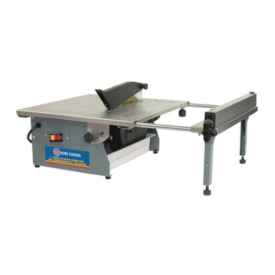
- Page 1 7” PORTABLE TILE SAW WITH EXTENSION TABLE MODEL: KC-3004ST INSTRUCTION MANUAL COPYRIGHT © 2012 ALL RIGHTS RESERVED BY KING CANADA TOOLS INC.
-
Page 2: Warranty Information
LIMITED TOOL WARRANTY King Canada makes every effort to ensure that this product meets high quality and durability standards. King Canada warrants to the original retail consumer a 2-year limited warranty as of the date the product was purchased at retail and that each product is free from defects in materials. - Page 3 GENERAL SAFETY RULES FOR POWER TOOLS 1. KNOW YOUR TOOL 13. DON’T OVERREACH. Read and understand the owners manual and labels affixed to Keep proper footing and balance at all times. the tool. Learn its application and limitations as well as its 14.
-
Page 4: Specific Safety Rules
Do not use this tile saw to cut wood or metal! This tile saw is to be used solely for its intended purpose. Any use other than its intended use is a case of misuse. The user /operator and not King Canada shall be liable for any damage or injury resulting from cases of misuse. - Page 5 For circuits that are further away from the electrical circuit box, the wire size must be increased proportionately in order to deliver ample voltage to the Tile Saw motor. Refer to Fig. 2 for extension cord length and size (gauge). MODEL KC-3004ST Blade diameter 7”...
-
Page 6: Assembly & Set-Up
ASSEMBLY / SET-UP CAUTION: Follow all the assembly & installation instructions completely before connecting the tile saw to a power source. Carefully open and remove all the components and packing materials from the box. ASSEMBLING DIAMOND CUTTING BLADE 1) First remove the water tray from underneath the table. 2) Undo the pan head screws (A) Fig.3 and remove the lower blade guard (B) and lower blade guard plate (C). -
Page 7: Assembly And Operation
ASSEMBLY & OPERATION INSTALLING ASSEMBLED RIP FENCE ON THE TABLE 1) To install the rip fence assembly (A) Fig.7 onto the table or the extension table, first lift the clamp lever (B). 2) Slide the front and back clamps onto the table, once the rip fence is in the desired position, lower the clamp lever (B) to secure the rip fence. -
Page 8: Operation And Maintenance
OPERATION & MAINTENANCE CUTTING OPERATIONS For straight cuts, once the rip fence is positioned for the desired cut, place the material flush against the rip fence then push the material towards the blade. A push block is supplied for this type of operation. For diagonal cuts, to obtain diagonal cuts, follow the steps for straight cuts above, in addition the V-groove push block is used.
Need help?
Do you have a question about the KC-3004ST and is the answer not in the manual?
Questions and answers