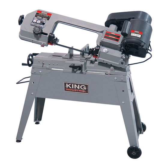
Summary of Contents for King Canada KC-129C
-
Page 1: Instruction Manual
KING CANADA 5” X 6” METAL CUTTING BANDSAW MODEL: KC-129C INSTRUCTION MANUAL COPYRIGHT © 2008 ALL RIGHTS RESERVED BY KING CANADA TOOLS INC. -
Page 2: Warranty Information
LIMITED TOOL WARRANTY King Canada makes every effort to ensure that this product meets high quality and durability standards. King Canada warrants to the original retail consumer a 2-year limited warranty as of the date the product was purchased at retail and that each product is free from defects in materials. -
Page 3: General Safety Instructions
GENERAL & SPECIFIC SAFETY INSTRUCTIONS GENERAL SAFETY INSTRUCTIONS 1. KNOW YOUR TOOL 12. ALWAYS WEAR SAFETY GLASSES. Read and understand the owners manual and labels affixed to the Always wear safety glasses (ANSI Z87.1). Everyday eyeglasses only have impact resistant lenses, they are NOT safety glasses. tool. -
Page 4: Electrical Information
SOURCE. FAILURE TO COMPLY MAY RESULT IN SERIOUS INJURY! KC-129C POWER SUPPLY (120V-1 PHASE) WARNING: YOUR KC-129C (120V) MUST BE CONNECTED TO A 120V, 15-AMP, BRANCH CIRCUIT. FAILURE TO CONNECT IN THIS WAY CAN RESULT IN INJURY FROM SHOCK OR FIRE. - Page 5 12) Blade guides 13) Gear Box 14) Pulley cover 15) Belt tension lock knob 16) Stand wheel set BANDSAW SPECIFICATIONS MODEL KC-129C Cutting capacity at 90˚ Rect. 4-1/2” x 6” Diam. 5” Cutting capacity at 45˚ Rect. 3” x 4-1/2” Diam. 3”...
- Page 6 ASSEMBLY & SETUP INSTRUCTIONS BEFORE OPERATING BANDSAW Assembling Stand, Wheel Set and Mounting Bandsaw (Fig.3) 1) Assemble the stand legs (A & E) Fig.3 and the 4 horizontal bars (B) together using 8 carriage bolts,8 washers and 8 hex. nuts. 2) Once the stand legs and horizontal bars are assembled, assemble the cross braces (C) on top of each end of the stand using 8 carriage bolts, 8 washers and 8 hex.
- Page 7 ASSEMBLY & SETUP INSTRUCTIONS BEFORE OPERATING BANDSAW Installation of the Belt and Pulley Cover, Belt and Tensioning Belt To install the belt and pulley cover; 1) Place the belt and pulley cover fixing plate (A) Fig.7 around the pulleys as shown in Fig.7 and fix it into place with 2 hex.
- Page 8 SETUP & OPERATION INSTRUCTIONS BEFORE OPERATING BANDSAW Adjusting Vise Angle To adjust the angle of the vise; 1) Loosen hex. bolt (A) Fig.11 and slide the vise (B) to the desired angle. Use the scale (C) as a guide to set your angle. 2) Retighten hex.
- Page 9 SETUP & OPERATION INSTRUCTIONS, REPLACING BLADE Blade Selection Material Speed (FPM) Belt groove used 1) A 14 tooth per inch, general-use blade is furnished with this metal 60Hz Motor pulley Drive pulley cutting band saw. Tool, stainless or alloy 2) The choice of blade pitch is governed by the thickness of the work to steel, bearingbronzes.
- Page 10 ADJUSTING BLADE & GENERAL MAINTENANCE Adjusting the Tracking of the Blade The blade tracking has been set at the factory and will rarely need to be adjusted if the bandsaw is used correctly. To adjust the tracking of the blade; 1) Turn the blade tension knob (A) Fig.19 counterclockwise so that the blade loosens a little.
-
Page 11: Troubleshooting Guide
TROUBLESHOOTING GUIDE CORRECTIVE ACTION PROBLEM POSSIBLE CAUSE 1. Clamp work securely. Excessive blade 1. Materials loose in vise. 2. Incorrect speed or feed. 2. Adjust speed or feed. breakage 3. Replace with a small teeth spacing blade. 3. Blade teeth spacing too large. 4.


Need help?
Do you have a question about the KC-129C and is the answer not in the manual?
Questions and answers