Table of Contents

Subscribe to Our Youtube Channel
Related Manuals for Dennis Premier 30”


Summary of Contents for Dennis Premier 30”
-
Page 1: Instruction Manual
PREMIER RANGE INSTRUCTION MANUAL DENNIS, Ashbourne Road, Kirk Langley, Derby, DE6 4NJ, United Kingdom Telephone:- 01332 824 777 Fax:- 01332 824 525 E-mail:- sales@dennisuk.com E-mail:- spares@dennisuk.com SP20005_REV_2 www.dennisuk.com 10/12... -
Page 3: Declaration Of Conformity
Ian Howard Serial Numbers MAKE A NOTE OF THE SERIAL NUMBERS OF YOUR MACHINE & ENGINE AND ALWAYS NOTE QUOTE THEM IN ANY COMMUNICATION WITH PERSONNEL AT DENNIS. MACHINE SERIAL NUMBER ENGINE SERIAL NUMBER Introduction The reliability and quality of performance of this machine depends upon some simple care maintenance carried out regularly. -
Page 4: Table Of Contents
Contents Page Product Application Matrix ..............................2 Declaration of Conformity ..............................3 Serial Numbers ..................................3 Introduction ................................... 3 Technical Data ..................................4 Machine Description ................................5 Important Safety Instructions ..............................6 Controls ....................................7 Operating Instructions ..............................8 - 9 General Adjustments ..............................10 - 11 Routine Maintenance.............................. -
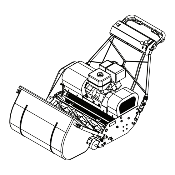
Page 5: Machine Description
Machine Description Manufactured with a 30” (76.2cm) and 36” (91.4cm) cutting width this mower is powered by a 11 h.p. four stroke, petrol engine or a 6 h.p. diesel engine. The rear roller and cylinder are powered via two automotive friction clutches. This allows for independant control of motion and cutter. -
Page 6: Important Safety Instructions
TRAINING READ THE INSTRUCTIONS CONTAINED IN THIS MANUAL WITH CARE. IF YOU ARE IN CAUTION ANY DOUBT PLEASE ASK YOUR EMPLOYER OR CONTACT US DIRECT AT DENNIS. • Be familiar with the controls and the proper use of the equipment. -
Page 7: Controls
Controls FOR THE LOCATION OF CONTROLS AND COMPONENTS REF. “MACHINE DESCRIPTION” PAGE 5. ON / OFF SWITCH (Item 17) This key switch starts the engine and can be used to stop the engine at anytime during the operation of the machine. DEADMANS CONTROL (Item 13) This is an operator presence control. -
Page 8: Operating Instructions
Operating Instructions BEFORE YOU OPERATE THIS MACHINE YOU MUST READ AND STUDY THIS MANUAL. CAUTION IF YOU ARE IN ANY DOUBT PLEASE ASK YOUR EMPLOYER OR CONTACT US DIRECT. FOR THE LOCATION OF CONTROLS AND COMPONENTS REF. “MACHINE DESCRIPTION” PAGE 5. PREPARATION FOR USE • Ensure the turf is free from stones or other obstructions which may damage the cutting cylinder. - Page 9 Operating Instructions TO COMMENCE DRIVING (TRANSPORT BETWEEN SITES / NO CUTTING) • Raise the “Deadmans” lever (item 13) • Push the “Drive Control” lever (item 10) forwards. • Set the “Throttle control” to increase / reduce speed. STOP DRIVING • Pull the “Drive Control” lever (item 10) backwards. RELEASING THE “DEADMANS”...
-
Page 10: General Adjustments
General Adjustments SETTING FOR HEIGHT OF CUT Always stop the engine before adjusting the height of cut. Failure to do this may result in serious injury. The length of grass after cutting and the depth of scarification / dethatching / brushing, depends on the setting of the front roller in relation to the main frame of the machine. - Page 11 General Adjustments SETTING THE CYLINDER Item 1 To set: • Slacken 2-off lock nuts and bolts (Item 1) [19mm spanner] • Rotate bolt (Item 2) clockwise to bring the blade towards the cylinder. Item 2 • Check the setting using thin paper along the length of the cylinder. • Adjust until it cuts along the whole length. • When set, tighten the lock nut. • Recheck adjustment. • Do not set the cylinder hard to the bottom blade. This will cause excessive wear of both components and increase fuel consumption. • Recheck Adjustment. DO NOT SET THE CYLINDER HARD TO THE BOTTOM BLADE. THIS WILL CAUSE NOTE EXCESSIVE WEAR OF BOTH COMPONENTS AND INCREASE FUEL CONSUMPTION.
-
Page 12: Routine Maintenance
Routine Maintenance ENGINE Honda GX340 Petrol Engine. For full specifications please refer to the manufacturers instruction manual included. Area Maintenance First 4 Hours First Month / 20 Hours 3 Months / 50 Hours 6 Months / 100 Hours Engine Oil Check Level ü Engine Oil Change ü ü Check Condition / Air Filter ü... -
Page 13: Storage
Routine Maintenance REAR ROLLER Oil Plug The rear roller is split into 3-sections incorporating a differential gear system running in an oil bath. Change oil every 6-months Oil Type:-EP90 GEAR OIL Oil Qty:- 568ML DRIVING CHAINS The rear roller and the cylinder are chain driven from the gearbox. These are located under the cover on the right hand side plate. -
Page 14: Parts Listings
1.01 Chassis Item No. Part No. Description Quantity Item No. Part No. Description Quantity 146328 30” Scraper Bar SP03030 Washer M12 Toothed 146330 36” Scraper Bar SP05001 Rivet 4.8 x 10 171885 Cassette Thrust Plate 176474 Locking Strip 176475 Front Bar Spacer 176476 Rear Bar Spacer 185641... - Page 15 2.01 Rear Roller - Main Assembly Item No. Part No. Description Quantity 065824 Bearing RLS9-2RS 089575 Key 3/16” x 3/16” x 2 1/4” RD End 176507 Spacer Plate 185660 Locking Collar (Small) 185662 Locking Collar 185698 30” Rear Roller Shaft 185699 36”...
- Page 16 2.02 Rear Roller - Outer Assembly Item No. Part No. Description Quantity 052601 Gear Differential Wheel 158374 Rear Roller Bush 171660 30” Outer Roller 171661 36” Outer Roller SP01036 Hex Set Screw M8 x 35 SP03004 Washer M8 Toothed Premier SP20005_REV_2...
- Page 17 2.03 Rear Roller - Centre Assembly Item No. Part Number Description Quantity 016386 Key Woodruff 3/16” x 7/8” 052602 Gear Differential Pinion 158356 Thrust Washer Soft 158357 Washer Thrust Hard 158372 Gear Diff Double Pinion 158373 Shaft Differential Pinion 185664 Centre Roller Prem 185665 Pivot Differental Pinion...
- Page 18 2.04 Rear Roller - LH Brake Assembly Item No. Part No. Description Quantity 185437 Brg Housing Rear Roller L.H. MD961 Brake Plate 6” SP13004 Spring Brake Steer MD964 Brake Shoe MD967 Brake Cam L.H. MD969 Brake Lever L.H. MD971 Cable Shackle (B Steer) SP01043 Cap Head M5 x 16 SP01086...
- Page 19 2.05 Rear Roller - RH Brake Assembly Item No. Part No. Description Quantity 176370 Cover Plate 185436 Brg Housing Rear Roller R.H. MD961 Brake Plate 6” MD962 Spring Brake Steer (Heavy) MD963 Spring Brake Steer (Light) MD964 Brake Shoe (Prem) MD968 Brake Cam R.H.
- Page 20 49 14 3.01 Handle Item No. Part No. Description Quantity Item No. Part No. Description Quantity 127434 Red Knob M10 SP01076 Hex Set Screw M8 x 16 176457 Black Knob M10 SP01082 Hex Set Screw M12 x 50 178400 Handle Bracket Assy SP01087 Hex Bolt 1/2”...
-
Page 21: Cutting Unit
4.01 Cutting Unit Item No. Part No. Description Quantity 062276 Bearing 6207-2RS 3 065696 Bearing 6206-2RS 3 067171 30” Shear Blade Lipped 086792 36” Shear Blade Lipped 171697 30” Pivot Bar 171698 36” Pivot Bar 185359 Cassette Side Plate R.H. W.A. 185378 Screw 3/8”... - Page 22 5.01 Grassbox Item No. Part No. Description Quantity 209025 30” Grass Box 209026 36” Grass Box 208897 Grass Box Bracket R.H. 208896 Grass Box Bracket L.H. 209030 Grass Box Pivot Bolt 208895 Back Plate SP01028 Hex Set Screw M6 x 20 SP02004 Nut M6 Nyloc Premier...
- Page 23 6.01 Gearbox Item No. Part No. Description Quantity Item No. Part No. Description Quantity 001155 Clutch Pin SP06015 Bearing BA1210Z 029342 Dowel 3/8” x 1 1/2” 065696 Bearing 6206-2RS 3 068633 Seal O Ring 9/16” x 3/32” 171702 Grub Screw 3/8” BSPT 176384 Gear Idler (Prem G’box) 176388...
-
Page 24: Clutch Assembly
13 8 7.01 Clutch Assembly Item No. Part No. Description Quantity Item No. Part No. Description Quantity 001155 Clutch Pin SP01086 Hex Set Screw 5/16” UNF x 5/8” 062662 Bearing 6205-2RS 3 SP01091 Hex Set Screw 5/16” UNF x 1/2” 065696 Bearing 6206-2RS 3 SP01093... -
Page 25: Front Roller
8.01 Front Roller Item No. Description Part Number Quantity 176402 Front Roller Brk Assy R.H. (STD) 176403 Front Roller Brk Assy L.H. (STD) 176411 30” Scraper Front Roller 176416 36” Scraper Front Roller 185880 30” Premier Front Roller 185883 36” Premier Front Roller 185885 Front Roller Special Nut (UNF) SP01065... - Page 26 25 20 9.01 Drive - Main Assembly 1 Item No. Description Part Number Quantity Item No. Description Part Number Quantity 62662 Bearing 6205-2RS 3 228049 Key 1/4” x 1/4” x 1 1/4” Rd End NOT SHOWN (Kubota Diesel) 230065 Drive Plate 230066 G’box Guard MD914...
- Page 27 9.02 Drive - Main Assembly 2 Item No. Description Part Number Quantity 230065 Drive Plate 230066 G’box Guard 230076 Bearing Housing (G’box Plate) 230077 Spacer Layshaft Driven See 9.03 Drive Assy SP01031 Hex Set Screw M10 x 50 SP02008 Nut M10 Nyloc SP03011 Washer M10 Form A SP10001...
- Page 28 9.03 Drive - Drive Assembly Item No. Part No. Description Quantity 230070 Drive Tube Assembly 230075 Shaft Honda Drive 062662 Bearing 6205-2RS 3 Premier SP20005_REV_2...
- Page 29 Gearbox Cover MD675 Battery Cover 230080 Drive Guard (Honda Only) 228031 Chain Case Seal 1735mm 260125 Premier STD Decal 260140 Throttle Decal J20362 Dennis Small Decal B32903 Union Jack Decal B32902 Medium Dennis Decal B21309 Large Dennis Decal Premier SP20005_REV_2...
- Page 30 DENNIS, Ashbourne Road, Kirk Langley, Derby, DE6 4NJ, United Kingdom Telephone:- 01332 824777 Fax:- 01332 824 525 E-mail:- sales@dennisuk.com E-mail:- spares@dennisuk.com www.dennisuk.com...
Need help?
Do you have a question about the Premier 30” and is the answer not in the manual?
Questions and answers