Table of Contents
Advertisement
Quick Links
Advertisement
Table of Contents

Subscribe to Our Youtube Channel
Related Manuals for Dennis RAZOR 560


Summary of Contents for Dennis RAZOR 560
- Page 1 RAZOR 560 & RAZOR ULTRA 560 INSTRUCTION MANUAL...
-
Page 3: Table Of Contents
HANDLEBAR ADJUSTMENT ROUTINE MAINTENANCE GENERAL LUBRICATION PARTS BOOK SERIAL NUMBERS NOTE:- MAKE A NOTE OF THE SERIAL NUMBER OF YOUR MACHINE AND ALWAYS QUOTE IT IN ANY COMMUNICATION WITH PERSONNEL AT DENNIS CHASSIS SERIAL NUMBER ENGINE SERIAL NUMBER INTRODUCTION The reliability and quality of performance of this machine depends upon some simple care maintenance carried out regularly. -
Page 4: Certificate Of Conformity
CERTIFICATE OF CONFORMITY EU DECLARATION OF CONFORMITY Razor Ultra Cylinder Mower powered by Honda GX Petrol Engine Manufacturer:- - Howardson Ltd, Howardson Works, Kirk Langley, Derby, DE6 4NJ. UK Owner of Technical Document:- - Mr I.D. Howard, Howardson Ltd, Howardson Works Kirk Langley, Derby, DE6 4NJ, UK Notified Body:- - Vincotte, NB0026, Jan Olieslagerslaan 35, B-1800 Vilvoorde, Belgium I the undersigned declare that this machine:-... -
Page 5: Technical Data
TECHNICAL DATA Model Razor 560 Razor Ultra 560 A - Width (mm) B - Length with Grassbox (mm) 1172 1220 C - Length without Grassbox (mm) D - Height (mm) 1170 1170 Weight (Kg) Cutting Width (mm) Cylinder 7 Blades... -
Page 6: Machine Description
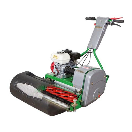
MACHINE DESCRIPTION Manufactured with a 22” (56cm) cutting width this mower is powered by a 4 h.p. air cooled, single cylinder, four stroke, petrol engine. The rear roller and cylinder are powered via independent friction clutches. This allows infinite speed control of the machine independent of the cylinder speed. In the design of the machine, special attention has been given to the importance of easy service and maintenance, with the construction based on a sectional assembly system. -
Page 7: Important Safety Instructions
TRAINING READ THE INSTRUCTIONS CONTAINED IN THIS MANUAL WITH CARE. IF YOU ARE IN CAUTION ANY DOUBT PLEASE ASK YOUR EMPLOYER OR CONTACT US DIRECT AT DENNIS. • Be familiar with the controls and the proper use of the equipment. -
Page 8: Controls
CONTROLS FOR THE LOCATION OF CONTROLS AND COMPONENTS REF. “MACHINE DESCRIPTION” PAGE 5. ON / OFF SWITCH (Item 17) This switch stops the engine and can be used to do so at anytime during the operation of the machine. Ensure it is in the “ON”... -
Page 9: Operating Instructions
OPERATING INSTRUCTIONS BEFORE YOU OPERATE THIS MACHINE YOU MUST READ AND STUDY THIS MANUAL. CAUTION IF YOU ARE IN ANY DOUBT PLEASE ASK YOUR EMPLOYER OR CONTACT US DIRECT. FOR THE LOCATION OF CONTROLS AND COMPONENTS REF. “MACHINE DESCRIPTION” PAGE 5. PREPARATION FOR USE •... - Page 10 OPERATING INSTRUCTIONS (CONTINUED) TO COMMENCE CUTTING Raise the “Deadmans” lever (Item 13) • • Engage the “Cylinder Control” Lever (Item 15) • Press the “Control Hoop” (Item 12) to the handle bar to start moving. Set the “Throttle Control” to increase / reduce speed. •...
-
Page 11: Setting For Height Of Cut
10. SETTING FOR HEIGHT OF CUT SETTING FOR HEIGHT OF CUT Always stop the engine before adjusting the height of cut. Failure to do this may result in severe injury. The length of grass after cutting depends on the setting of the front roller in relation to the main frame of the machine. -
Page 12: Groomer (Razor Ultra Only)
11. GROOMER (RAZOR ULTRA ONLY) GROOMER (RAZOR ULTRA ONLY) The groomer unit has been designed to be removed easily from the “Chassis” for maintenance purposes. It is driven from the cylinder by a robust timing belt. The groomer is NOT a deep scarifier. Failure to use correct will invalidate the warranty and could cause damage to the drive system. -
Page 13: Handlebar Adjustment
13. HANDLEBAR ADJUSTMENT HANDLE BAR ADJUSTMENT The “Handle bars” are adjustable to achieve the correct working height for the operator. To set: • Slacken 4-off nuts (Item 1) ¼” turn [17mm spanner] • Raise / lower the “Handle Bar” to the desired position”... -
Page 14: Routine Maintenance
14. ROUTINE MAINTENANCE ENGINE The machine is fitted with a Honda GX120 petrol engine. For full specifications please refer to the manufacturers instruction manual included. Area Maintenance First 4 Hours First Month / 20 Hours 3 Months / 50 Hours 6 Months / 100 Hours Engine Oil Check Level... -
Page 15: General Lubrication
15. GENERAL LUBRICATION REAR ROLLER (6-months) The main drive roller is split into three sections incorporating a differential gear system running in an oil bath. The old oil should be drained off and the bath replenished with 1 pint (550ml) of clean oil. (1-month) A grease point is located under the belt guard on the side plate of the machine. -
Page 16: Parts Book
14 21 1.01 Chassis Item No. Part No. Description Quantity 228062 3/4” Tube Bung (3132) 229342 Scraper Bar 22” 240001 Side Plate L.H. (Ultra) 240220 Side Plate L.H. (Std) 240002 Side Plate R.H. (Ultra) 240221 Side Plate R.H. (Std) 240003 Engine Deck Assy 22”... - Page 17 2.01 ‘T’ & ‘D’ Handle Item No. Part No. Description Quantity 229166 Handle Pivot Bush 229378 Cutter Drive Clutch Cable 230200 Handle Bracket W.A. 230203 Handle Buffer 230205 Handle Bracket Support 800202 ‘D’ Handle Assy* SP01044 Coach Bolt M10 x 25 SP01047 Hex Set Screw M10 x 60 SP02008...
- Page 18 40 16 2.02 ‘D’ Handle - Main Assembly Item No. Part No. Description Quantity Item No. Part No. Description Quantity 229167 Clutch Spring SP03010 Washer M6 Form A 229599 Engine On / Off Decal SP03012 Washer M12 Form A 229620 Bolt For Spring SP03019 Washer M12 Wave...
- Page 19 2.03 ‘T’ Handle - Main Assembly Item No. Part No. Description Quantity 229167 Clutch Spring 229599 Engine On / Off Decal 229723 Roller Drive Cable G610 229754 Clutch Lever Lever 230170 Lever R.H. W.A. 240027A Guard Handle (Tee Bar) 240169 Sensor Angle Plate 240171 Cutter Control Plate...
- Page 20 3.01 Rear Roller - Main Assembly Item No. Part Number Description Quantity 062662 Bearing 6205-2RS 3 229011 Pinion Shaft 11T 229031 Dirt Excluder 229033 Roller Bearing Housing Oblong 240151 Shaft Extension L.H. 240152 Shaft Extension R.H. 800198 Rear Roller Assy 22” J20052 Bearing 6204-2RS 3 SP01045...
- Page 21 3.02 Rear Roller - Roller Assembly Item No. Part No. Description Quantity 062662 Bearing 6205-2RS 3 228049 Key 1/4” x 1/4” x 1 1/4” Rd End 229022 30 Tooth Bevel Gear 229023 Bush Oilite MBC AJ2024 x 1.5 229025 20 Tooth Bevel Gear 229030 Internal Gear 229032...
- Page 22 4.01 Front Roller - Main Assembly Item No. Part No. Description Quantity 800148 Click Height Adjuster L.H.* 800149 Click Height Adjuster R.H.* 800214 Weile Roller Assy 22” (Razor)** SP01019 Button Head M6 x 16 240105 Roller End Block Assembly SP02010 Nut M12 Nyloc SP02014 Nut M12 Lock (Thin)
- Page 23 4.02 Front Roller - Click Height Adjusters Item No. Part No. Description Quantity J20517 Ht. Adjuster Block J20518 Height Adjuster Knob 228092 Shim Id 25.8 x 1 Thk J20519 Decal Height Of Cut J20528 Grease Nipple 1/4” Bsp J20525 Steel Ball 8mm J20526 Spring SP02013...
- Page 24 4.03 Weile Roller Assembly Item No. Part No. Description Quantity 229833 Bush Oilite AL1622 - 20 230262 Weile Roller Stub Shaft 240108 Weile Roller Body 22” Razor J209068 Nut Locking J209071 Seal Single Lip J209105 Bearing 6201-2RS SP02014 Nut M12 Lock (Thin) SP07003 Circlip D1300 0320 SP20002_REV2-1...
- Page 25 5.01 Cylinder - Main Assembly Item No. Part No. Description Quantity 240034 Cylinder Alignment Collar R.H. (Ultra) 240225 Cylinder Alignment Collar R.H. (Std) 240037 Cylinder Alignment Collar L.H. 240086 Slot Cover 800196 Cylinder Assy 22” (Ultra)* 800215 Cylinder Assy 22” (Std)* 800213 Pulley Assy Cylinder SP01054...
- Page 26 5.02 Cylinder - Cylinder Assembly Item No. Part No. Description Quantity D315163175 Belleville Washer 228074 Cylinder 22” 11 Blade (135 X 559) 240030 Cylinder 22” 7 Blade (135 X 559) 240230 Bearing Housing Cylinder R.H. 240040 Bearing Housing Cylinder L.H. 240041 Shear Blade Adjuster Assy Shear 800224...
- Page 27 22 27 13 13 19 6.01 Engine & Drive Kit - Main Assembly Item No. Part No. Description Quantity Item No. Part No. Description Quantity 228011 Coupling Half (3/4”) SP11019 Belt Ribbed 4pk 800 228103 Coupling Element SP11020 Belt Ribbed 4pk 625 229013 Pulley Spacer SP11021...
- Page 28 22 27 13 13 19 6.01 Engine & Drive Kit - Main Assembly Item No. Part No. Description Quantity Item No. Part No. Description Quantity 228011 Coupling Half (3/4”) SP11019 Belt Ribbed 4pk 800 228103 Coupling Element SP11020 Belt Ribbed 4pk 625 229013 Pulley Spacer SP11021...
- Page 29 6.02 Engine & Drive Kit - Clutch Item No. Part No. Description Quantity 240011 Clutch Pressure Plate 240012 Clutch Shaft 240013 Clutch Bearing Housing 240016 Clutch Drive Bearing Housing 240017 Friction Plate Assy 240018 Clutch Spring Washer J20052 Bearing 6204-2RS 3 J20255 Bearing 5205 - 3205 2RS J209246...
- Page 30 27 26 28 RAZOR ULTRA 560 ONLY 7.01 Groomer Assembly Item No. Description Part Number Quantity SP07006 Circlip D1400-20 240110 Groomer Drive 240111 Pulley 30-5M-25 Finished 240112 Pulley 15-5M-15 Finished 240113 Groomer Drive Shaft 240114 Groomer Actuator 240117 Groomer Actuator Pin Assy 240119 Groomer Spring Plate 240133...
- Page 31 8.01 Brake Assembly Item No. Description Part Number Quantity 240180 Brake Bracket 240181 Brake Pin 240182 Brake Disc 240183 Brake Retainer 240184 Brake Flag J20110 Lever Grip SP12005 Micro Switch* SP01019 Button Head M6 x 16 SP01070 Cap Head M2 x 12 SP02004 Nut M6 Nyloc SP02006...
- Page 32 SP02004 Nut M6 Nyloc SP04002 Screw M6 x 16 Slotted 800203 22” Grass Box Assy (Razor Ultra 560) 800216 22” Grass Box Assy (Razor 560) 240260 Grass Box Mesh Assembly Front 240206 Grass Box Mesh Assembly Rear SP20002_REV2-1 RAZOR PAGE 32...
- Page 33 10.01 Guards & Decals Item No. Part No. Description Quantity SP18002 Decal Drive (Razor) J20362 Dennis Decal Small SP18003 Decal Cutter (Razor) 229375 Warning Decal 1332903 Union Jack Decal 229603 Parking Brake Decal 229376 Cut Decal 240025 Guard Belt 228031B...
- Page 34 11.01 Wheel Kit - Main Assembly Item No. Part No. Description Quantity 228024 1” Tube Bung 229167 Clutch Spring 240160 Stand Transport Wheels 240164 Stand Spring Pin 240167 Stand Bush 800210 Transport Wheel Assy L.H.* 800211 Transport Wheel Assy R.H.* SP02006 Nut M8 Nyloc SP03017...
- Page 35 11.02 Wheel Kit - L.H. Wheel Item No. Part No. Description Quantity 228042 Circlip D1300 0520 240091 Wheel Assy 240094 Wheel Hub 240095 Hub Shaft 240097 Plunger J20527 Circlip D1460 - 25 J209112 Knob Plastic SP01034 Hex Set Screw M10 x 20 SP01051 Grub Screw M5 x 10 SP05009...
- Page 36 11.03 Wheel Kit - R.H. Wheel Item No. Part No. Description Quantity 228042 Circlip D1300 0520 240091 Wheel Assy 240094 Wheel Hub 240095 Hub Shaft 240097 Plunger J20527 Circlip D1460 - 25 J209112 Knob Plastic SP01034 Hex Set Screw M10 x 20 SP01051 Grub Screw M5 x 10 SP05009...
- Page 37 DENNIS, Ashbourne Road, Kirk Langley, Derbyshire, DE6 4NJ, England Tel: +44 (0) 1332 824 777 Fax: +44 (0) 1332 824 525 Email: sales@dennisuk.com A division of Howardson Ltd – a proudly British company Email: spares@dennisuk.com Company reg No: 641526 – Vat No GB 345 9918 12...
Need help?
Do you have a question about the RAZOR 560 and is the answer not in the manual?
Questions and answers