Rane AC 23B Operator's Manual
Active crossover
Hide thumbs
Also See for AC 23B:
- Operator's manual (18 pages) ,
- Datasheet (4 pages) ,
- Datasheet (4 pages)
Advertisement
Quick Links
Download this manual
See also:
Operator's Manual
CH 1
LOW
MASTER
2W: INACTIVE
4
6
4
6
4
2
8
2
8
2
0
10
0
10
MIN
LEVEL
LEVEL
MUTE
DELAY
MONO MASTER
SUBWOOFER
QUICK START
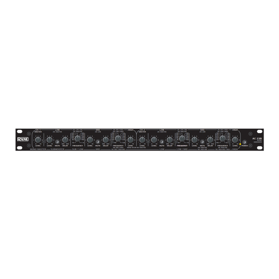
Labels above the controls refer to the unit being operated in the 2- or 3-Way Stereo mode. Labels below the
controls refer to the unit being operated in the 4- or 5-Way Mono mode.
Set the STEREO/MONO switch appropriately. The fact that the AC 23B is a multiple function unit means the outputs
are switched around in Mono mode.
To operate the unit in Stereo 3-Way mode, be sure the rear panel switches are set for STEREO 3-WAY. Following the
labels above the controls and jacks in logical order, you will find Channel 1 Master Input LEVEL, LOW Output, MID
Output, and HIGH Output, with the same for Channel 2. If you need a summed Mono Low Ouput, see 'Monoing the Low
Outputs' on page Manual-7.
To use the unit as a Mono 5-Way, first check that the CHANNEL 1 and 2 switches are set to 3-WAY, and the other
switch is set to MONO. Connect the INPUT source to CHANNEL 1 only. Following the labels below the jacks, look at
SUB OUT, then look over at LOW OUT, now go back to MID OUT, then over to HIGH-MID OUT and then proceed to
the HIGH OUT. An internal switch determines 4 or 5-Way mode. Our apologies to 4-Way users: We must ship the units in
the 5-Way mode since normal Stereo 3-Way operation demands it: a fact not the least bit obvious, but nevertheless, a fact
it remains. Pity. See page Manual-6 for Mono 4-Way configuration.
In agreement with IEC and AES/ANSI standards, AC 22B wiring convention is pin 2 Positive, pin 3 Negative (return),
pin 1 chassis ground. See the "Sound System Interconnection" RaneNote included with this manual for more information
on cabling and grounding requirements.
CAUTION: Never connect anything except an approved Rane Power supply to the thing that looks like a red
telephone jack on the rear of the AC 23B. This is an 18 VAC center tapped power input. Consult the Rane factory for a
replacement or substitution.
WEAR PARTS: This product contains no wear parts.
OPERATORS MANUAL
3W: LOW / MID
MID
3W: MID / HIGH
2W: INACTIVE
2W: LOW
2W: LOW / HIGH
240
400
700
200
600
550
6
4
6
4
6
150
750
475
100
850
350
80
900
250
8
2
8
2
8
70
1k
190
MAX
0
10
MIN
MAX
FREQUENCY
LEVEL
MUTE
DELAY
FREQUENCY
4W: MID / HIGH
SUB / LOW
MID
5W: MID / HIGH-MID
HIGH
CH 2
LOW
MASTER
2W: INACTIVE
1.0k
2.0k
4
6
4
6
4
6
4
6
2.8k
4.5k
5.8k
2
8
2
8
2
8
2
7.0k
0
10
0
10
0
10
MIN
MAX
LEVEL
LEVEL
LEVEL
MUTE
DELAY
MONO 4W OR 5W: INACTIVE
LOW
ACTIVE CROSSOVER
3W: LOW / MID
MID
3W: MID / HIGH
2W: INACTIVE
2W: LOW
2W: LOW / HIGH
240
400
700
200
600
550
4
6
4
6
150
750
475
100
850
350
80
900
250
8
2
8
2
8
70
1k
190
0
10
MIN
MAX
FREQUENCY
FREQUENCY
LEVEL
MUTE
DELAY
FREQUENCY
4W: INACTIVE
4W: INACTIVE
LOW / MID
5W: HIGH-MID
5W: HIGH-MID / HIGH
AC 23B
HIGH
1.0k
2.0k
4
6
2.8k
4.5k
AC 23B
5.8k
2
8
ACTIVE
CROSSOVER
7k
0
10
LEVEL
POWER
HIGH
Manual-1
Advertisement

Subscribe to Our Youtube Channel
Related Manuals for Rane AC 23B


Summary of Contents for Rane AC 23B
- Page 1 CAUTION: Never connect anything except an approved Rane Power supply to the thing that looks like a red telephone jack on the rear of the AC 23B. This is an 18 VAC center tapped power input. Consult the Rane factory for a replacement or substitution.
- Page 2 2W: INACTIVE 2W: LOW / HIGH MASTER 2W: INACTIVE 2W: LOW MASTER 2W: INACTIVE 2W: LOW 1.0k 1.0k 2.0k 2.0k 2.8k 2.8k 4.5k 4.5k AC 23B 5.8k 5.8k ACTIVE CROSSOVER 7.0k LEVEL LEVEL MUTE DELAY FREQUENCY LEVEL MUTE DELAY FREQUENCY LEVEL...
-
Page 3: Chassis Grounding
Low Amp Observe the labels above the Inputs and Outputs for Stereo operation. CHANNEL 1 INPUT: Plug the left output of the mixer, equalizer or other signal source to this Input. See ‘AC 23B Connection’ on page Manual-1 for wiring details. - Page 4 2W: LOW / HIGH MASTER 2W: INACTIVE 2W: INACTIVE 2W: LOW 2W: LOW / HIGH 2W: INACTIVE 1.0k 1.0k 2.0k 2.0k 2.8k 2.8k 4.5k 4.5k AC 23B 5.8k 5.8k ACTIVE CROSSOVER 7.0k LEVEL LEVEL MUTE DELAY FREQUENCY LEVEL MUTE DELAY FREQUENCY...
- Page 5 Observe the labels above the Inputs and Outputs for Stereo operation. CHANNEL 1 INPUT: Plug the left output of the mixer, equalizer or other signal source to this Input. Refer to ‘AC 23B Connection’ on page Manual-1 for wiring details.
- Page 6 * NOTE: Both the CHANNEL 1 HIGH LEVEL control and CHANNEL 2 MASTER LEVEL control are automatically bypassed when the AC 23B is switched to "MONO" on the back panel. Adjusting these controls has no effect in the Mono mode.
- Page 7 3. Move the switch from the 5-WAY position to 4-WAY. 2. Move the header to the J10 mono sum position. 4. Replace the cover. The AC 23B is now set for Mono 4- 3. Moving the header to the SHIP position puts the Low Way Mode.
- Page 8 HlGH-MID OUTPUT (FOR MONO 5-WAY ONLY): Use this Output only for Mono 5-Way applications. Omit this output when using the AC 23B as a Mono 4-Way Crossover. Mono 4-Way Switch Instructions are on the previous page. In 4-Way the AC 23B internally bypasses the High-Mid section and defeats all front panel High-Mid Controls. For Mono 5-Way connect the HIGH-MID OUT to the input of the high-mid frequency amplifier.
- Page 9 1 to 3-Way, and CHANNEL 2 to 2-Way. POWER input connector. Use only a model RS 1 or other power supply approved by Rane. This unit is supplied with a remote power supply suitable for connection to this input jack.
- Page 10 The one catch is that in many cases it is a frequency error greater than a full detent on the AC 23B. physically or otherwise impossible to get all the drivers vertically lined up at the sound source.
- Page 11 2 through 5 for each lower crossover point. time delay. Some references will be made to the Rane RA 30 NOTE: If you are running two separate channels on the...
- Page 12 SPL meter (obtainable at that the high driver is actually in front of the mid driver; most local electronics stores, the best is the Rane RA 30) and adding delay to the mid driver only worsens the situa- some kind of variable tone generator.
- Page 13 It is very important that the meter drivers. The built-in delay system in the AC 23B is remain in exactly the same position throughout the test, so designed to accommodate the majority of common affix it to a mic stand, small tree or other stable object.
- Page 14 In order to phase-align two drivers you must observe only Delay vs. Frequency Table the crossover frequency, which is common to both drivers. If you do not have the equipment necessary to electroni- Pink noise can be used if all other frequencies are disre- cally align the system as described in previous sections, you garded, since room acoustics and imperfect driver response may use the table below to obtain a rough and approximate...
- Page 15 6. Adjust the display controls on the analyzer so that it shows the hands of an expert. This does require experience, skill, the greatest number of 0 dB LED’s (green on Rane and the right equipment to back it up (not to mention a equipment) below the crossover point.
- Page 16 Now go back and re-adjust the previous cross- over level controls, turning these down to get a 0 dB f µ reading on the meter. ©Rane Corporation 10802 47th Ave. W., Mukilteo WA 98275-5098 USA TEL 425-355-6000 FAX 425-347-7757 WEB www.rane.com Manual-16 106002...
Need help?
Do you have a question about the AC 23B and is the answer not in the manual?
Questions and answers