Table of Contents
Advertisement
DIGITAL VIDEO CAMERA
GR-DX55
GR-DX45
GR-DX35
GR-DX25
Please visit our Homepage on the World Wide Web for Digital
Video Camera:
http://www.jvc-victor.co.jp/english/cyber/
For Accessories:
http://www.jvc-victor.co.jp/english/accessory/
INSTRUCTIONS
ENGLISH
CONTENTS
AUTOMATIC
DEMONSTRATION
GETTING STARTED
TAPE
RECORDING &
PLAYBACK
ADVANCED
FEATURES
REFERENCES
EN
LYT1120-001A
6
7 – 10
11 – 15
16 – 33
34 – 47
Advertisement
Table of Contents

Related Manuals for JVC GR-DX25


Summary of Contents for JVC GR-DX25
-
Page 1: Digital Video Camera
DIGITAL VIDEO CAMERA GR-DX55 GR-DX45 GR-DX35 GR-DX25 Please visit our Homepage on the World Wide Web for Digital Video Camera: http://www.jvc-victor.co.jp/english/cyber/ For Accessories: http://www.jvc-victor.co.jp/english/accessory/ INSTRUCTIONS ENGLISH CONTENTS AUTOMATIC DEMONSTRATION GETTING STARTED 7 – 10 TAPE RECORDING & PLAYBACK 11 – 15... -
Page 2: Table Of Contents
SAFETY PRECAUTIONS SOME DO’S AND DON’TS ON THE SAFE USE OF EQUIPMENT PROVIDED ACCESSORIES HOW TO ATTACH THE LENS CAP HOW TO ATTACH THE CORE FILTER AUTOMATIC DEMONSTRATION GETTING STARTED Power ... 7 – 8 Grip Adjustment ... 8 Viewfinder Adjustment ... 8 Tripod Mounting ... -
Page 3: Dear Customer
However, live recording and LCD monitor/viewfinder playback are possible anywhere. Use the JVC BN-V107U/V114U battery packs and, to recharge them or to supply power to the camcorder from an AC outlet, use the provided multi-voltage AC Adapter and Power Cord. -
Page 4: Above All
The following notes concern possible physical damage to the camcorder and to the user. Do not carry or hold the camcorder by the viewfinder and/or the LCD monitor as this can result in dropping the unit, or in a malfunction. -
Page 5: Provided Accessories
In order to maintain optimum performance of the camcorder, provided cables may be equipped with one or more core filter. If a cable has only one core filter, the end that is closest to the filter should be connected to the camcorder. -
Page 6: How To Attach The Core Filter
Core Filter. Stopper When connecting cables, attach the end with the Core Filter to the camcorder. Automatic Demonstration takes place when “DEMO MODE” is set to “ON” (factory-preset). Automatic Demonstration starts when there is no operation for about 3 minutes after the Power Switch and no cassette is in the camcorder. -
Page 7: Getting Started
VU-V856 KIT : BN-V856U battery pack & AA-V80EK Viewfinder on Read the kit's instruction manual before using. Also, by using the optional JVC VC-VBN856U DC 1 hr. 25 min. Cord, it will be possible to connect BN-V840U or BN-V856U battery packs to the camcorder and supply 2 hrs. -
Page 8: Power ............................................................ 7
• Unplug the AC Adapter from the AC outlet. • Detach the battery from the camcorder. This camcorder will be automatically turned off if its power is supplied from the AC adapter and about 5 minutes pass since it has entered into the recording standby mode with a cassette inserted. -
Page 9: Tripod Mounting
Tripod Mounting CAUTION When attaching the camcorder to a tripod, extend its legs to stabilise the camcorder. It is not advised to use small sized tripods. This may cause damage to the unit by falling over. To attach the camcorder to a tripod, align the screw to the mounting socket on the camcorder. -
Page 10: Getting Started 7
Closing the cassette holder cover before the cassette holder comes out may cause damage to the camcorder. Even when the camcorder is switched off, a cassette can be loaded or unloaded. After the cassette holder is closed with the camcorder switched off, however, it may not recede. -
Page 11: Basic Recording
NOTES: If the Record-Standby mode continues for 5 minutes, the camcorder’s power shuts off automatically. To turn the camcorder on again, push back and pull out the pg. 23) and viewfinder again or close and re-open the LCD monitor. When a blank portion is left between recorded scenes on the tape, the time code is interrupted and errors may occur when editing the tape. -
Page 12: Zooming
Power-Linked Operation When the Power Switch is set to “ also turn on/off the camcorder by opening/closing the LCD monitor or pulling out/pushing in the viewfinder. TAPE RECORDING To produce the zoom in/out effect, or an instantaneous change in image magnification. -
Page 13: Time Code
When recording is resumed, the time code starts counting up again from “00:00:00”. This means the camcorder may record the same time codes as those existing in a previously recorded scene. To prevent this, perform “RECORDING FROM THE MIDDLE OF A TAPE”... -
Page 14: Blank Search
... press 5 NOTES: In step 3, if the current position is at a blank portion the camcorder searches in the reverse direction, and if the current position is at a recorded portion the camcorder searches in the forward direction. -
Page 15: Connections
Connections Make sure all units are turned off. Connect the camcorder to a TV or VCR as shown in the illustration. If using a VCR . . . go to step 3. If not . . . go to step 4. -
Page 16: For Recording
• “GAIN UP” in the CAMERA Menu ( • “DIS” in the MANUAL Menu ( During Night-Scope, it may be difficult to bring the camcorder into focus. To prevent this, use of manual focus and/or a tripod is recommended. Programme AE With Special Effects Set the Power Switch to “... -
Page 17: Fade/Wipe Effects
Fade/Wipe Effects These effects let you make pro-style scene transitions. Use them to spice up the transition from one scene to the next. Fade or Wipe works when tape recording is started or when you stop recording. Set the Power Switch to “... -
Page 18: Snapshot Recording
” or When shooting a subject close to the lens, zoom out first camcorder may automatically zoom out depending on the distance between the camcorder and the subject. This will not occur when “TELE MACRO” ( “BEEP” on pg. 23. -
Page 19: Manual Focus
Power Switch to “ ”. If FOCUS is pressed once, the camcorder will enter the focus adjustment mode again. NOTES: Be sure to focus the lens in the maximum telephoto position when you use the Manual Focus mode. If you... -
Page 20: White Balance Adjustment
If the white balance is correct, all other colours will be accurately reproduced. The white balance is usually adjusted automatically. However, more advanced camcorder operators control this function manually to achieve a more professional colour/tint reproduction. Set the Power Switch to “... -
Page 21: Sound Mode
For Recording Menu This camcorder is equipped with an easy-to-use, on-screen menu system that simplifies many of the more detailed camcorder settings ( Set the Power Switch to “ down the Lock Button located on the switch. Open the LCD monitor fully or pull out the viewfinder fully. -
Page 22: Using Menus For Detailed Adjustment
• When shooting subjects with excessive backlighting. • When shooting scenes with movement in various directions. • When shooting scenes with low-contrast backgrounds. Switch off this mode when recording with the camcorder on a tripod. The “ ” indicator blinks or goes out if the Stabiliser cannot be used. - Page 23 If no operation is performed for more than 3 minutes after that, the demonstration will resume. NOTES: If a tape is in the camcorder, the demonstration cannot be turned on. “DEMO MODE” remains “ON” even if the camcorder power is turned off.
-
Page 24: For Playback Menu
TIME CODE [OFF]: Time code is not displayed. ON: Time code is displayed on the camcorder and on the connected TV. Frame numbers are not displayed during recording. CLOCK ADJ. Allows you to set the current date and time (... -
Page 25: Video Display
SOUND 2: Dubbed sound is output on both “L” and “R” channels in stereo. [ ] = Factory-preset NOTES: • The camcorder cannot detect the sound mode in which the recording was made during fast-forward or rewind. During playback the sound mode is displayed in the upper left corner. -
Page 26: Dubbing
Repeat steps 4 through 6 for additional editing, then stop the VCR and camcorder when finished. NOTES: As the camcorder starts to play your footage it will appear on your TV. This will confirm the connections and the AUX channel for dubbing purposes. -
Page 27: Dubbing To Or From A Video Unit Equipped With A Dv Connector (Digital Dubbing)
( If the remote control is used when both the player and recorder are JVC video units, both units will perform the same operation. To prevent this from happening, press the buttons on both units. -
Page 28: Using The Remote Control Unit
(0) repeatedly. Playback Special Effects To start playback, press PLAY (4) Point the remote control at the camcorder’s remote . The PLAYBACK Move the highlight bar to the desired effect by . The selected function is activated on the remote control. Pressing it again re-... -
Page 29: Audio Dubbing
Make sure you only edit recorded areas. If feedback or howling occurs during TV playback, move the camcorder’s microphone away from the TV, or turn down the TV’s volume. If you change from 12-bit to 16-bit in mid-recording and then use the tape for Audio Dubbing, it is not effective from the point where 16-bit recording began. -
Page 30: Random Assemble Editing [R.a.edit]
PHILIPS HITACHI GOLDSTAR USING THE REMOTE CONTROL UNIT Although the MBR is compatible with JVC VCRs and those of many other makers, it may not work with yours or may offer limited functions. NOTES: If the VCR’s power does not come on in step 1, try another code from the VCR CODE LIST. - Page 31 To PAUSE IN * Connect when the S-Video connection is not used. ** When connecting cables, open this cover. SELECT SCENES Point the remote control at the camcorder’s remote sensor. Press PLAY (4) and then press R.A.EDIT ON/OFF on the remote control.
-
Page 32: For More Accurate Editing
USING THE REMOTE CONTROL UNIT Some VCRs make the transition from Record-Pause to Record mode faster than others. Even if you begin editing for the camcorder and the VCR at exactly the same time, you may lose scenes you wanted, or find , or that you have recorded scenes you did not want. -
Page 33: System Connections
When using a DV cable, be sure to use the optional JVC VC-VDV206U or VC-VDV204U DV cable depend- ing on the type of DV connector (4 or 6 pins) on the The system may not work properly depending on the PC or capture board you are using. -
Page 34: Recording Cannot Be Performed
Before consulting your JVC dealer, please check the following to see it you can correct the problem yourself. The camcorder is a microcomputer-controlled device. External noise and interference (from a TV, a radio, etc.) might prevent it from functioning properly. In such cases, first disconnect its power supply unit (battery pack, AC Adapter, etc.) and wait... - Page 35 • When the LCD monitor's fluorescent light reaches the end of its service life, images on the LCD monitor become dark. Consult your nearest JVC dealer. ¥ Adjust the brightness and angle of the LCD monitor pg. 11).
- Page 36 If the indication remains even though you repeat the above two or three times, please consult your nearest JVC dealer. Do not eject the cassette. This will cause damage to the tape. An error indication (E03 or E04) appears.
- Page 37 1. To prevent damage to the LCD monitor, DO NOT ..push it strongly or apply any shocks..place the camcorder with the LCD monitor on the bottom. 2. To prolong service life . . .
-
Page 38: Cautions
20 seconds, it stops automatically. Also refer to the cleaning cassette’s instructions. If, after using the cleaning cassette, the problems still exist, consult your nearest JVC dealer. Mechanical moving parts used to move the video heads and video tape tend to become dirty and worn out over time. - Page 39 Serious malfunctioning If malfunctioning occurs, stop using the unit immediately and consult your local JVC dealer. The camcorder is a microcomputer-controlled device. External noise and interference (from a TV, a radio, etc.) might prevent it from functioning properly.
-
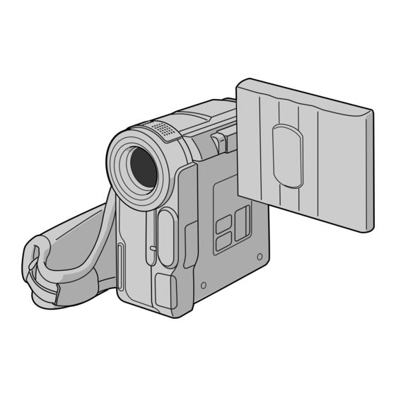
Page 40: Index
Controls, Connectors And Indicators Refer to this diagram while reading the instructions. LCD monitor Stereo microphone Speaker Viewfinder Remote Control INDEX... - Page 41 7 pg. 8 pg. 8 pg. 9 pg. 11 pg. 7 * Functions the same as each corresponding button on the camcorder. pg. 9 The connectors pg. 28 pg. 28 pg. 15, 26, 30 pg. 28, 30 pg. 28 pg.
-
Page 42: Lcd Monitor/Viewfinder Indications
INDEX LCD Monitor/Viewfinder Indications During Tape Recording 0 x W SOUND b i t 5 : 55 During Tape Playback SOUND BLANK SEARCH VOLUME 116 : 21 : 24 1h50m & 25 . 12 . 03 25 . 12 . 03... - Page 43 Appears when the iris is locked ... • SOUND: Displays the sound mode for approx. 5 seconds after turning on the camcorder ... • BRIGHT: Displays the brightness of the LCD monitor ... Appears when Digital Image Stabiliser (“DIS”) is engaged ...
-
Page 44: Warning Indications
” or minutes for the indication to clear. When it does, you can resume using the camcorder. If the indication remains, consult your nearest JVC dealer. E03 or E04 UNIT IN SAFEGUARD MODE EJECT AND REINSERT TAPE The error indications (E03 or E04) show what type of malfunction has occured. -
Page 45: Specifications
Camcorder General Power supply : DC 11.0 V DC 7.2 V Power consumption LCD monitor off, viewfinder on : Approx. 3.4 W LCD monitor on, viewfinder off : Approx. 4.6 W Dimensions (W x H x D) : 55 mm x 102 mm x 96 mm... -
Page 46: Terms
Blank Search ... Brighten The LCD Monitor ... Channels (Left/Right) ... Charge The Battery Pack ... Cinema ... Classic Film ... Clean The Camcorder ... Connections ... Darken The LCD Monitor ... Date/Time Display ... Date/Time Settings ... Demonstration Mode ... - Page 47 Random Assemble Editing ... Record-Standby ... Recording Mode ... Remote Control ... Reset ... Rewind The Tape ... Self-Recording ... Sepia ... Set Remote Control/VCR Code ... Shuttle Search ... Shutter Speed ... Slow-Motion Playback ... Snapshot ... Snapshot Mode ... Snow ...
- Page 48 VICTOR COMPANY OF JAPAN, LIMITED Printed in Japan 0103-HO-UN-SN1 COPYRIGHT© 2003 VICTOR COMPANY OF JAPAN, LTD.
Need help?
Do you have a question about the GR-DX25 and is the answer not in the manual?
Questions and answers
What type of cable do I need to charge the jvc-700x camera?
The JVC GR-DX25 camera is charged using an AC Adapter, not a USB cable. The USB cable is used for data transfer only.
This answer is automatically generated
The LCD screen and viewfinder is black - it is not showing an image and I have turned it off and on again. Everything else is fine.
The LCD screen and viewfinder on the JVC GR-DX25 may appear black if the camcorder is not getting power or if another malfunction exists. To address this issue:
1. Turn the camcorder's power off and then on again.
2. If the LCD monitor's fluorescent light has reached the end of its service life, the screen may appear dark. In this case, consult your nearest JVC dealer.
This answer is automatically generated