Download Print this page
JVC GR-DX107EK Service Manual
Hide thumbs Also See for GR-DX107EK:

Advertisement

SERVICE MANUAL
2004
4
YF046
GR-DX107EK, GR-DX107EX, GR-DX107EY,
GR-DX107EZ, GR-DX307EK, GR-DX307EX,
GR-DX307EY, GR-DX307EZ, GR-DX317EX
For disassembling and assembling of MECHANISM ASSEMBLY, refer to the SERVICE MANUAL No.86700(MECHANISM ASSEMBLY).
1
PRECAUTIONS . . . . . . . . . . . . . . . . . . . . . . . . . . . . . . . . . . . . . . . . . . . . . . . . . . . . . . . . . . . . . . . . . . . . . . . 1-3
2
SPECIFIC SERVICE INSTRUCTIONS . . . . . . . . . . . . . . . . . . . . . . . . . . . . . . . . . . . . . . . . . . . . . . . . . . . . . . 1-5
3
DISASSEMBLY . . . . . . . . . . . . . . . . . . . . . . . . . . . . . . . . . . . . . . . . . . . . . . . . . . . . . . . . . . . . . . . . . . . . . . . 1-6
4
ADJUSTMENT . . . . . . . . . . . . . . . . . . . . . . . . . . . . . . . . . . . . . . . . . . . . . . . . . . . . . . . . . . . . . . . . . . . . . . . 1-15
5
TROUBLE SHOOTING . . . . . . . . . . . . . . . . . . . . . . . . . . . . . . . . . . . . . . . . . . . . . . . . . . . . . . . . . . . . . . . . . 1-18
COPYRIGHT © 2004 VICTOR COMPANY OF JAPAN, LIMITED
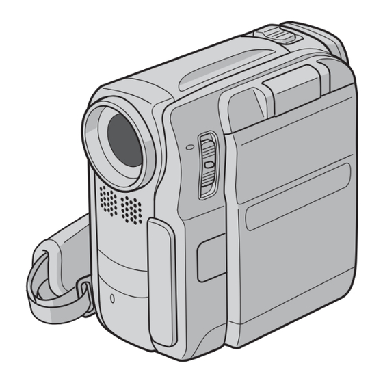
DIGITAL VIDEO CAMERA
TABLE OF CONTENTS
GR-DX107EK, GR-DX107EX, GR-DX107EY, GR-DX107EZ[M4D3S9]
GR-DX307EK, GR-DX307EX, GR-DX307EY, GR-DX307EZ, GR-DX317EX[M4D3M9]
No.YF046
2004/4

Advertisement

loading

Summary of Contents for JVC GR-DX107EK

  • Page 1 2004 GR-DX107EK, GR-DX107EX, GR-DX107EY, GR-DX107EZ, GR-DX307EK, GR-DX307EX, GR-DX307EY, GR-DX307EZ, GR-DX317EX GR-DX107EK, GR-DX107EX, GR-DX107EY, GR-DX107EZ[M4D3S9] GR-DX307EK, GR-DX307EX, GR-DX307EY, GR-DX307EZ, GR-DX317EX[M4D3M9] For disassembling and assembling of MECHANISM ASSEMBLY, refer to the SERVICE MANUAL No.86700(MECHANISM ASSEMBLY). TABLE OF CONTENTS PRECAUTIONS ............... 1-3 SPECIFIC SERVICE INSTRUCTIONS .
  • Page 2 SPECIFICATION 1-2 (No.YF046)
  • Page 3: Precautions

    SECTION 1 PRECAUTIONS SAFTY PRECAUTIONS Prior to shipment from the factory, JVC products are strictly emission. Consequently, when servicing these products, inspected to conform with the recognized product safety and replace the cathode ray tubes and other parts with only the electrical codes of the countries in which they are to be specified parts.
  • Page 4 1.1.2 Safety Check after Servicing Examine the area surrounding the repaired location for damage (4) Leakage current test or deterioration. Observe that screws, parts and wires have been Confirm specified or lower leakage current between earth returned to original positions, Afterwards, perform the following ground/power cord plug prongs and externally exposed tests and confirm the specified values in order to verify accessible parts (RF terminals, antenna terminals, video...
  • Page 5: Specific Service Instructions

    SECTION 2 SPECIFIC SERVICE INSTRUCTIONS The following table indicate main different points between models GR-DX107EK, GR-DX107EX, GR-DX107EY, GR-DX107EZ, GR-DX307EK, GR-DX307EX, GR-DX307EY, GR-DX307EZ and GR-DX317EX. MODEL GR-DX107EK GR-DX107EX GR-DX107EY GR-DX107EZ GR-DX307EK LCD MONITOR 2.5INCH 2.5INCH 2.5INCH 2.5INCH 3.0INCH BODY COLOR Silver & Silver Silver &...
  • Page 6: Disassembly

    SECTION 3 DISASSEMBLY BEFORE ASSEMBLY AND DISASSEMBLY • 3.1.1 Precautions Torque driver • Be sure to disconnect the power supply unit prior to mounting Be sure to use to fastening the mechanism and exterior parts and soldering of parts. because those parts must strictly be controlled for tightening •...
  • Page 7 3.2.2 ASSEMBLY/DISASSEMBLY OF CABINET PARTS AND ELECTRICAL PARTS Disassembly procedure NOTE13: STEP Fig. PART NAME POINT NOTE For the disassembly procedure of the OP BLOCK ASSEM- BLY/CCD BOARD ASSEMBLY, see "3.2.5 DISASSEMBLY CASSETTE COVER ASSY Fig.C1 GRIP BELT ASSY,2(S1),HOOK(F) NOTE1 of [13] OP BLOCK ASSMBLY/CCD BOARD ASSEMBLY"...
  • Page 8 (S1) (S1) NOTE1 (S1) (S1) (S1) COVER(ADJ) HOOK(F) NOTE1 (S1) (S1) Fig.C1 NOTE4a (S3) (S3) (S4a) (S4a) (S4a) (S4c) COVER(DV) (S4a) ASSEMBLY NOTE4b (S4a) (S2a) (S4a) JACK COVER ASSEMBLY (S2b) NOTE4b (S4b) Fig.C2 Fig.C3 1-8 (No.YF046)
  • Page 9 (S5) (S5) NOTE5 (S5) (S5) (S5) COVER(JIG CON) : 0.078N m(0.8kgf Fig.C4 NOTE6 BKT(MIC) ASSEMBLY (S6) (S7) NOTE7 (S7) (S6) (S6) (S6) (S6) Fig.C5 (No.YF046)1-9...
  • Page 10 [10] (S10) [11] CN11e CN11b CN11c (S11) (S11) CN11a CN10 (S11) NOTE8 NOTE11 CN11d (S8) (S8) Fig.C6 Fig.C8 [12] (S9) (S9) NOTE12a, b BKT(TOP)ASSEMBLY (S12) (S12) (S12) (S12) (S9) CN9a (S13) CN9b NOTE9 [13] NOTE13 (S9) (S9) (S9) (S9) (S9) Fig.C7 Fig.C9 1-10 (No.YF046)
  • Page 11 (S14) SHIELD COVER (S14) L14a CN14c NOTE14 SPACER(A) CN14a [14] CN14b L14b : 0.069N m(0.7kgf Fig.10 [16] NOTE16 BKT(PRE-REC) CN16d (S16a) CN16c (S16b) CN16b CN16a (S16b) (S16b) BKT(MECHA)ASSEMBLY [15] (S15) (S15) : 0.069N m(0.7kgf : 0.078N m(0.8kgf Fig.C11 (No.YF046)1-11...
  • Page 12 3.2.3 DISASSEMBLY of [9] MONITOR ASSEMBLY CAUTIONS (3) While removing the five screws (6-10) in numerical order (1) During the procedure, be careful in handling the LCD and disengaging the two hooks (L9a and L9b) in alpha- MODULE,etc., especially not to damage or soil the mon- betical order, remove the MONITOR COVER ASSY.
  • Page 13 3.2.4 DISASSMBLY of [12] VF ASSEMBLY Disassembly (7) Remove the FPC attached to the GUIDE (OUTER) little (1) Remove the EYE CUP. by little so that the FPC moves easily, and remove the COVER (VF) from the GUIDE (OUTER). NOTE12a: After the EYE CUP is removed, be careful of handling NOTE12c: the EYE CUP since the SHEET (LENS) is removed.
  • Page 14 3.2.5 DISASSEMBLY of [13] OP BLOCK ASSMBLY/CCD BOARD ASSEMBLY CAUTIONS Assembly procedure of OP BLOCK ASSEMBLY/CCD (1) During the procedure, remove the OP BLOCK ASSEMBLY BOARD ASSEMBLY if necessary. When removing the OP BLOCK ASSEMBLY, (1) Attach the OP LPF to the OP BLOCK ASSEMBLY, and be careful not to damage the lens.
  • Page 15: Adjustment

    SECTION 4 ADJUSTMENT PREPARATION 4.1.3 TOOLS REQUIRED FOR ADJUSTMENT 4.1.1 Precaution Torque Driver Tweezers YTU94088 YTU94088-003 P-895 Camera system and deck system of this model are specially adjusted by using PC. However, if parts such as the following are replaced, an adjustment is required.
  • Page 16 • Guide driver (Hexagonal) JIG CONNECTOR CABLE CONNECTION To be used to turn the guide roller to adjustment of the linarity • Remove one screw (1), and remove the COVER (JIG CON). of playback envelope. • As the figure shows, insert JIG CONNECTOR CABLE in JIG •...
  • Page 17 Jig connector diagrams MECHANISM COMPATIBILITY ADJUSTMENT 4.3.1 Tape pattern adjustment JIG CONNECTOR CABLE (YTU93106C) NOTE: Prior to the adjustment, remove the COVER (ADJ). MAIN CN105 (1) Play back the compatibility adjustment tape. NOTE : (2) While triggering the HID1, observe the waveform of The JIG CONNECTOR BOARD uses ENV_OUT.
  • Page 18: Trouble Shooting

    SECTION 5 TROUBLE SHOOTING SERVICE NOTE 1-18 (No.YF046)
  • Page 19 TAKE OUT CASSETTE TAPE The following procedure is a method for taking out the cassette tape in case the cassette tape cannot be ejected due to an elec- (DC3V) trical failure. The following procedure is a simplified method; CASSETTE COVER therefore, for more reliable operation, it is recommended that you should remove exterior parts so that you can take out the tape without excessive force.
  • Page 20 EMERGENCY DISPLAY Example (in case of the error number E01): Whenever some abnormal signal is input to the syscon CPU, an error number (E01, as an example) is displayed on the LCD monitor or (in the electronic view finder).In every error status, UNIT IN REMOVE AND such the message as shown below alter nately appear over and...
  • Page 21 VICTOR COMPANY OF JAPAN, LIMITED AV & MULTIMEDIA COMPANY CAMCORDER CATEGORY 12, 3-chome, Moriya-cho, kanagawa-ku, Yokohama, kanagawa-prefecture, 221-8528, Japan (No.YF046) Printed in Japan...
  • Page 22: Digital Video Camera

    GR-DX107EK, GR-DX107EX, GR-DX107EY, GR-DX107EZ, GR-DX307EK, GR-DX307EX, GR-DX307EY, GR-DX307EZ, GR-DX317EX CD-ROM No.SML200405 GR-DX107EK, GR-DX107EX, GR-DX107EY, GR-DX107EZ[M4D3S9] GR-DX307EK, GR-DX307EX, GR-DX307EY, GR-DX307EZ, GR-DX317EX[M4D3M9] For disassembling and assembling of MECHANISM ASSEMBLY, refer to the SERVICE MANUAL No.86700(MECHANISM ASSEMBLY). No.YF046SCH COPYRIGHT © 2004 VICTOR COMPANY OF JAPAN, LIMITED...
  • Page 23 CIRCUIT BOARD NOTES CHARTS AND DIAGRAMS 1. Foil and Component sides NOTES OF SCHEMATIC DIAGRAM 4. Voltage measurement 1) Foil side (B side) : Parts on the foil side seen from foil face (pattern face) 1) Regulator (DC/DC CONV) circuits Safety precautions are indicated.
  • Page 24 BOARD INTERCONNECTION YTU94074-28 YTU94074-20 YTU94077-28 YTU94077-20 INT/R EM_AU/R EM_AU/R INT_GND MD_AU/L MD_AU/R INT/L EM_AU/L EM_AU/L (Page 2-43) MD_AU/R MD_AU/L CN7002 ( E_MIC_GND) CN111 EM_DET_L ( E_MIC_L) EM_DET_L ( E_MIC_R) AUDIO_CS (Page 2-44) (Page 2-13) AU_DATA BUZZER (Page 2-11) SPK+ A_MUTE MD_DEM1 CN7001 SPK-...
  • Page 25 MAIN (MAIN_IF) SCHEMATIC DIAGRAM CN113 CN106 CN112 EJT_SW REG_4.8V IR_OUT IR_RMC TALLY LAMP_ON REG_4.8V CN104 LITHIUM J102 QNZ0497-001 USBSENS CN115 CN108 PWR_LED USB_DP CN109 USB_DN DIAL_PB R2004 TRIG_SW D2802 DIAL_OFF 3.3k KEY_B DIAL_AUTO DIAL_MAN U R2001 R2002 R2003 TELE_SW 3.3k 6.8k KEY_A MENU_SW...
  • Page 26 MAIN ( SYSCON ) SCHEMATIC DIAGRAM LIT_3V TO VIDEO I/O TO MAIN_IF REM_OUT IC1006 IC1005 VDO_CLK AL_3VSYS µ SCLK OSD_HD L1001 RS5C314-X M95320-WDW6-X OSD_CS AL_3.1V µ OSD_VD L1002 R1004 RTC_CS EEP_CS VDO_OUT X1002 REG_3.1V IC1003 DATA C1042 AVREFOFF AREG_CLK NAX0564-001X EEP_IN R1043 74HC1G00GW-X...
  • Page 27 MAIN( REEL ) SCHEMATIC DIAGRAM REEL REG_3.1V R1711 R1712 TO SYSCON S_REEL T_REEL R1702 2.2K R1701 R1710 120K R1709 R1703 2.2K M_REG4.8 R1713 IC1702 IC1701 C1703 10/6.3 NJM2407R-W BA10358FVM-W TO SYSCON T_RL[+] T_RL[-] R1707 R1704 S_RL[+] 2.2K S_RL[-] R1706 R1708 120K R1705 2.2K...
  • Page 28 MAIN ( AUDIO AD/DA ) SCHEMATIC DIAGRAM TO AUDIO TO DSC MD_AU/L DOBCK2 MD_AU/R DOMCK2 DOLRCK2 EM_AU/R DODAT2 EM_AU/L AIDAT2 IC2101 AK4550VT-X C2106 C2107 TO SYSCON R2101 R2102 PWDA2 PWAD2 C2102 C2101 L2101 TO REG 10µ C2108 4.7/6.3 REG_3.1V C2105 10/6.3 y30281001a_rev0.1 2-11...
  • Page 29 MAIN( AUDIO ) SCHEMATIC DIAGRAM Q2403 2SC5658-X REG_3.6V L2401 10µ REG_4.8V Q2401 2SC5658-X REG_3.1V R2401 R2402 4.7k 4.7k J101 C2402 QNS0233-001 D2652 10/6.3 EMZ6.8N-X C2401 R2408 C2404 R2403 L2651 NQR0269-013X 10/6.3 OPEN 10/6.3 L2652 NQR0269-013X R2232 OPEN Q2201 DTC144EE-X R2202 R2231 560k L2653...
  • Page 30 MAIN( DVMAIN ) SCHEMATIC DIAGRAM TO MAIN_IF R3021 TCMK OPEN TCMK TRST TRST R3022 CPUBUSTYPE CPUDSLOGIC C3047 MON0 CPUWAITLOGIC TO SYSCON MON1 CPUWAIT VDDE XINT XINT VDDI XCPUCS DV_CS MON2 XCPURW TO REG L3002 MON3 XCPUDSTB1 REG_3.1V MON4 XCPUDSTB0 NQR0129-002X TO CAMERA DSP REG_2.5V MON5...
  • Page 31 MAIN( VIDEO I/O ) SCHEMATIC DIAGRAM VIDEO I/O L3701 µ OUT_C0 R3738 C3701 OUT_C1 10/6.3 C3734 R3734 OUT_C2 R3736 OUT_C3 8.2k Q3733 L3731 C3732 EMZ1-W OUT_Y0 IC3201 C3739 µ 0.01 OUT_Y1 R3733 0.001 OUT_Y2 R3735 1.8k JCP8075 R3737 OUT_Y3 C3735 C3733 Q3731 C3738...
  • Page 32 MAIN ( PRE/REC ) SCHEMATIC DIAGRAM HID3 HID1 RECH MONI_CHG TL3501 TO JIG CONN. C3529 R3513 OPEN OPEN Q3501 IC3501 ENV_OUT R3515 OPEN OPEN JCY0132 ATFI C3531 OPEN C3530 OPEN C3517 C3527 0.01 220p C3518 0.01 C3519 0.001 TO OP DRV DUMP_CTL C3520 R3507...
  • Page 33 MAIN ( CDS ) SCHEMATIC DIAGRAM TO TG/V_DRIVER ADCLK PBLK IC4202 BH31FB1WHFV-W CPOB C4216 CDS_3V VOUT L4202 10µ STBY L4201 10µ TO REG CN102 C4217 C4204 C4201 QGF0532F2-20X 47/4 0. 1 REG_3.6V TO CCD C4218 C4205 47/4 C4206 CCD-7.5V R4202 CCD-7.5V CCD+15V TO CAMERA_DSP...
  • Page 34 MAIN ( CAMERA_DSP ) SCHEMATIC DIAGRAM L4304 NQR0129-002X X4301 L4305 TO MAIN_IF NQR0129-002X NAX0587-001X TCMK TCMK C4306 10/6.3 TRST TRST C4305 R4303 TO TG/V_DRIVER C4312 TO VIDEO I/O CLK9A CLK9A TG_36M OUT_VS TG_36M OUT_VS HDIN OUT_HS HDIN OUT_HS VDIN OUT_C3 VDIN OUT_C3 PBLK...
  • Page 35 MAIN ( OP DRV ) SCHEMATIC DIAGRAM OP DRV NQL38DK-100X L4701 µ R4736 100k R4705 560k C4712 R4722 R4721 R4704 C4711 0.01 C4704 R4723 R4701 R4707 R4724 R4717 R4718 100k HGOUT_1- HGVSS_1- HGOUT_1+ HGVCC_1+ TO SYSCON HALL_AD IRIS_O/C IRIS_PWM TO CAMERA_DSP D4901 RB751V-40-X R4905...
  • Page 36 MAIN ( TG/V_DRIVER ) SCHEMATIC DIAGRAM SYSCOM CCD_CTL TG_RST CAM_CLK CAM_OUT TG_CS CN102 QGF0532F2-20X L5006 L5007 10µ NQR0129-002X C5018 REG_3.6V CCD-7.5V C5017 C5016 C5021 REG+CCD CCD-7.5V 47/10 10/10 4.7/20 C5022 C5010 REG-CCD CCD+15V C5019 4.7/20 C5015 CCD+15V REG_3.1V L5004 L5005 10µ...
  • Page 37 MAIN ( REG ) SCHEMATIC DIAGRAM TO SYSCON I_MTR BATT. TERMINAL BATT_+ R6704 TO SYSCON R6701 Q6701 V_BATT D6702 J104 J104 J104 J104 J104 L6701 0.25W R6705 DG1M3-X NRV142F-R20X SSM3J14T-X R6702 C6101 100k L6101 C6701 F6101 2.0A µ D6701 DG1M3-X L6102 C6702 NMFZ007-2R0X-K...
  • Page 38 MAIN ( DSC ) SCHEMATIC DIAGRAM TO REG L8005 NQR0129-002X REG_1.8V REG_3.1V R8018 R8017 C8022 10/6.3 C8021 TO SYSCON 0.01 TL8015 FLSH_RST C8023 C8024 DSC_RST R8032 DSC_CLK 0Ω DSC_DT_OUT DSC_DT_IN DSC_CS R8025 R8023 R8022 4.7K 4.7K 0‘ MXDT_OUT DSC_STS CAPT_REQ IC8003 MMC_CD DSC_WKUP...
  • Page 39 MAIN ( USB ) SCHEMATIC DIAGRAM C8308 X8301 NAX0612-001X L8301 NQR0129-002X TO REG TO DSC REG_4.8V C8301 C8309 DSC_RST 10/6.3 DSC_RST GIO3 GIO3 TL8305 GIO6 GIO6 R8315 R8314 GIO15 GIO15 R8313 EM_CS2 0Ω EM_CS2 FLSH_OE FLSH_OE EM_CS2 FLSH_WE FLSH_WE TO MAIN_IF R8302 USB_DP C8305...
  • Page 40 MDA( MDA_IF ) SCHEMATIC DIAGRAM TO ROTARY ENCODER CN301 CN302 CN303 CN304 LOAD_REV LOAD_FWD DEW_SENS CN305 y30270001a_rev0.1 2-35 2-36...
  • Page 41 MDA ( MDA ) SCHEMATIC DIAGRAM TO SYSCON DRUM_PG DRUM_FG TL1601 TO REG DRUM_REF R1630 DRUM_ERR TL1612 R1639 D1604 DRUM_PWR DAP222-X C_FRB TL1618 C1632 CAP_FG 0.47 TL1602 CAP_REF R1631 TL1613 CAP_ERR C1607 R1640 NMFZ007-R20X-K LD_ON 0.047 CAP_PWR F1601 L_FRB M_UNREG TL1619 REG_3.1V F1602...
  • Page 42 FRONT SCHEMATIC DIAGRAM R6503 R6504 R6505 R6502 Q6503 Q6502 EMT1-W EMT1-W R6501 Q6501 DTC114EM- X D6501 D6503 D6502 CN401 LWE67C/U2V/4/-X LWE67C/U2V/4/-X LWE67C/U2V/4/-X IC401 RPM7138-S L401 R401 NQR0265-001X R402 1.5k D401 S401 BT401 SML-211UT-X Q401 NSW0122-001X QAB0040-001 C401 C402 RPM-22PB 10/6.3 y30283001a_rev0.1 2-39 2-40...
  • Page 43 MONITOR SCHEMATIC DIAGRAM TO LCD MODULE CN7603 JP7602 JP7603 JP7601 TO MAIN CN7601 REG_4.8V( BL) VSSG R7602 REG_4.8V( BL) XSTB REG_4.8V( BL) PC G REG_4.8V M_RVS L7603 REG_8.5V 10µ TEST HST_E WIDE HCK2 TEST1 HCK2 HCK1 VCOM-M XSTB-E HCK1 C7618 LCD_REF PSIG STB_E...
  • Page 44 VF SCHEMATIC DIAGRAM CCD SCHEMATIC DIAGRAM NOTES : For the destination of each signal and further line connections that are cut off from this diagram, refer to "BOARD INTERCONNECTIONS". When ordering parts, be sure to order according to the Part Number indicated in the Parts List. IC5501 is incorporated in the CCD base assembly.
  • Page 45 SD SCHEMATIC DIAGRAM L8501 NQR0006-001X REG_3.1V CN702 TO MAIN CN701 SD_DATA2 MMC_CS MMC_CS MMC_CS MMC_DIN MMC_DIN Dat2MMC MMC_CLK VSS( GND) C8503 MMC_CD VDD( DSC_3V) MMC_DOUT MMC_CLK MMC_CLK R8507 SD_WP MMC_CD C8501 VSS2/CD 0Ω 10/6.3 REG_3.1V MMC_DOUT Dat2Host SD_WP SD_DATA1 P_MEDIA D8501 EMZ6.8N-X TL8501...
  • Page 46 CAUTION : MAIN CIRCUIT BOARD FOR CONTINUED PROTECTION AGAINST FIRE HAZARD, REPLACE ONLY WITH SAME TYPE AND RATED FUSE(S). ATTENTION : POUR UNE PROTECTION PERMANENTE CONTRE LES RISQUE D'INCENDE, REMPLACER LES FUSIBLES PAR UN AUTRE DE MEME TYPE ET DE MEME TENSION. <01>...
  • Page 47 MAIN CIRCUIT BOARD <01> MAIN YB10472-01-01 FOIL SIDE(B) L5004 L2402 C1043 R1054 C2103 C2104 C2106 R2403 R1139 R1140 C2108 C2404 C2403 C2401 Q1003 Q1002 Q1001 L5006 C1703 R1026 L5005 R1060 C5016 C5021 R1002 R1084 IC1702 C1017 C5007 C5008 R2607 R1709 C1018 C2213 C2611...
  • Page 48 CAUTION : MDA CIRCUIT BOARD FRONT CIRCUIT BOARD FOR CONTINUED PROTECTION AGAINST FIRE HAZARD, REPLACE ONLY WITH SAME TYPE AND RATED FUSE(S). ATTENTION : POUR UNE PROTECTION PERMANENTE CONTRE LES RISQUE D'INCENDE, <04> FRONT <03> MDA REMPLACER LES FUSIBLES PAR UN AUTRE DE MEME TYPE ET DE MEME TENSION. YB10474 YB10459-01-01 FOIL SIDE(B)
  • Page 49 CAUTION : MONITOR CIRCUIT BOARD CCD CIRCUIT BOARD FOR CONTINUED PROTECTION AGAINST FIRE HAZARD, REPLACE ONLY WITH SAME TYPE AND RATED FUSE(S). ATTENTION : POUR UNE PROTECTION PERMANENTE CONTRE LES RISQUE D'INCENDE, <02> CCD <05> MONITOR REMPLACER LES FUSIBLES PAR UN AUTRE DE MEME TYPE ET DE MEME TENSION. YB10473-01-01 YB10461-01-01 FOIL SIDE(B)
  • Page 50 SD CIRCUIT BOARD <07> SD YB10463 FOIL SIDE(B) COMPONENT SIDE(A) L8501 R8504 R8506 TL8501 TL8501 C8502 R8502 C8501 C8503 R8501 CN702 2-55 2-56...
  • Page 51 POWER SYSTEM BLOCK DIAGRAM MAIN OP BLOCK REG-CCD CN102 CN5201 VIDEO I/O REG+CCD CCD-7.5V REG_3.1V IC5001 IC4202 IC5201 CCD-7.5V REG_3.6V CDS_3V 3V_REG CCD+15V IC3201 IC3731 REG_4.8V CCD+15V Q3701 Q3731 Q3733 Q5201 J104 IC5003 Q3734 Q3735 F6101 IC4201 IC5003 M_UNREG REG_3.1V DC JACK REG_3.6V REG_2.5V...
  • Page 52 VIDEO SYSTEM BLOCK DIAGRAM MAIN TPA+/-, TPB+/- J105 CN5201 CN102 IC5201 CCD_OUT DV JACK OP BLOCK (CCD Image sensor) IC4201 ADIN(0~9) SHD,SHP ( CDS/AGC/AD ) CN110 IC4301 REC_DATA DYI(0~3) IC3001 IC3501 DCI(0~3) ( CAMERA DSP ) HEAD IC5001 ATFI, AGC_OUT ADDT(0~15) ( PRE/REC AMP ) ( DV MAIN )
  • Page 53 VOLTAGE CHARTS <MAIN IF> <SYSCON> <AUDIO> <VIDEO I/O> <PRE/REC> <OP DRV> MODE MODE MODE MODE MODE MODE MODE MODE PIN NO. REC PLAY PIN NO. REC PLAY PIN NO. REC PLAY PIN NO. REC PLAY PIN NO. REC PLAY PIN NO. REC PLAY PIN NO.
  • Page 54 <TG/V_DRIVER> <REG> <USB> <MDA> <FRONT> <MONITOR> <CCD> MODE MODE MODE MODE MODE MODE MODE MODE MODE PIN NO. REC PLAY PIN NO. REC PLAY PIN NO. REC PLAY PIN NO. REC PLAY PLAY PLAY PIN NO. PIN NO. PIN NO. PINNO.
  • Page 55 VICTOR COMPANY OF JAPAN, LIMITED AV & MULTIMEDIA COMPANY CAMCORDER CATEGORY 12, 3-chome, Moriya-cho, kanagawa-ku, Yokohama, kanagawa-prefecture, 221-8528, Japan (No.YF046) Printed in Japan...
  • Page 56 Parts identified by the  symbol are critical for safety. Replace only with specified part numbers. BEWARE OF BOGUS PARTS Parts that do not meet specifications may cause trouble in regard to safety and performance. We recommend that genuine JVC parts be used. 1. EXPLODED VIEW 1.1 PACKING AND ACCESSORY ASSEMBLY <M1>...
  • Page 57 1.2 FINAL ASSEMBLY <M2> 504C 504A 504B 504D FRONT BOARD ASSEMBLY <04> 146G 146D 146D 146C 146E 146B SD BOARD 146A 146F 122A ASSEMBLY <07> 146F ASSEMBLY <M4> CCD BOARD ASSEMBLY <02> MECHANISM 101A ASSEMBLY <M3> 101A 101A < OP BLOCK ASSEMBLY > 112A 112A 112A...
  • Page 58 109A MAIN BOARD ASSEMBLY <01> MDA BOARD ASSEMBLY MONITOR <03> ASSEMBLY <M5> r F16 130A 128C 133B 128C 128C 128A 133B 133A 133B 128B 133B 128D (No.YF046)3-3...
  • Page 59 1.3 MECHANISM ASSEMBLY <M3> 900A YMA0029P YMA0029T Classification Part No. Symbol in drawing NOTE1: The section marked in AA, BB and CC Grease KYODO-SH-JB indicate lubrication and greasing areas. YTU94027 NOTE2: Mark is not contained in 900A. Grease (HANARL) RX-410R 3-4(No.YF046)
  • Page 60 1.4 VF ASSEMBLY <M4> VF BOARD ASSEMBLY <06> (No.YF046)3-5...
  • Page 61 1.5 MONITOR ASSEMBLY <M5> 810A MONITOR BOARD 810C ASSEMBLY <05> 810B For 3.0INCH For 2.5INCH For 3.0INCH For 2.5INCH 814A 814C 814B 814E 814G 814F 814D 3-6(No.YF046)
  • Page 62 MODEL MARK MODEL MARK MODEL MARK GR-DX107EK GR-DX107EZ GR-DX307EY GR-DX107EX GR-DX307EK GR-DX307EZ GR-DX107EY GR-DX307EX GR-DX317EX 2. PARTS LIST  Symbol No. PACKING AND ACCESSORY ASSEMBLY <M1> Part No. Part Name Description Local  Symbol No. Part No. Part Name Description...
  • Page 63 MODEL MARK MODEL MARK MODEL MARK GR-DX107EK GR-DX107EZ GR-DX307EY GR-DX107EX GR-DX307EK GR-DX307EZ GR-DX107EY GR-DX307EX GR-DX317EX  Symbol No.  Symbol No. Part No. Part Name Description Local Part No. Part Name Description Local LY30031-0F7A SPECIAL SCREW HOOK-ARM(x2) LY43725-001F TENSION ARM ASSY...
  • Page 64 MODEL MARK MODEL MARK MODEL MARK GR-DX107EK GR-DX107EZ GR-DX307EY GR-DX107EX GR-DX307EK GR-DX307EZ GR-DX107EY GR-DX307EX GR-DX317EX  Symbol No. Part No. Part Name Description Local MAIN BOARD ASSEMBLY <01>  Symbol No. Part No. Part Name Description Local LY33805-001B BRACKET LY30031-0E1A...
  • Page 65 MODEL MARK MODEL MARK MODEL MARK GR-DX107EK GR-DX107EZ GR-DX307EY GR-DX107EX GR-DX307EK GR-DX307EZ GR-DX107EY GR-DX307EX GR-DX317EX  Symbol No.  Symbol No. Part No. Part Name Description Local Part No. Part Name Description Local Q3003 2SC5658/QRS/-X TRANSISTOR C1036 NCFA1AZ-104W C CAPACITOR 0.1uF 10V Z...
  • Page 66 MODEL MARK MODEL MARK MODEL MARK GR-DX107EK GR-DX107EZ GR-DX307EY GR-DX107EX GR-DX307EK GR-DX307EZ GR-DX107EY GR-DX307EX GR-DX317EX  Symbol No.  Symbol No. Part No. Part Name Description Local Part No. Part Name Description Local C3001 NBZ0015-106X TA E CAPACITOR 10uF 6.3V M...
  • Page 67 MODEL MARK MODEL MARK MODEL MARK GR-DX107EK GR-DX107EZ GR-DX307EY GR-DX107EX GR-DX307EK GR-DX307EZ GR-DX107EY GR-DX307EX GR-DX317EX  Symbol No.  Symbol No. Part No. Part Name Description Local Part No. Part Name Description Local C4221 NCB30JK-105X C CAPACITOR 1uF 6.3V K...
  • Page 68 MODEL MARK MODEL MARK MODEL MARK GR-DX107EK GR-DX107EZ GR-DX307EY GR-DX107EX GR-DX307EK GR-DX307EZ GR-DX107EY GR-DX307EX GR-DX317EX  Symbol No.  Symbol No. Part No. Part Name Description Local Part No. Part Name Description Local C8016 NCB30JK-105X C CAPACITOR 1uF 6.3V K...
  • Page 69 MODEL MARK MODEL MARK MODEL MARK GR-DX107EK GR-DX107EZ GR-DX307EY GR-DX107EX GR-DX307EK GR-DX307EZ GR-DX107EY GR-DX307EX GR-DX317EX  Symbol No.  Symbol No. Part No. Part Name Description Local Part No. Part Name Description Local R2213 NRSA6AJ-2R7W MG RESISTOR 2.7Ω 1/16W J...
  • Page 70 MODEL MARK MODEL MARK MODEL MARK GR-DX107EK GR-DX107EZ GR-DX307EY GR-DX107EX GR-DX307EK GR-DX307EZ GR-DX107EY GR-DX307EX GR-DX317EX  Symbol No.  Symbol No. Part No. Part Name Description Local Part No. Part Name Description Local R4714 NRSA6AJ-683W MG RESISTOR 68kΩ 1/16W J...
  • Page 71 MODEL MARK MODEL MARK MODEL MARK GR-DX107EK GR-DX107EZ GR-DX307EY GR-DX107EX GR-DX307EK GR-DX307EZ GR-DX107EY GR-DX307EX GR-DX317EX  Symbol No.  Symbol No. Part No. Part Name Description Local Part No. Part Name Description Local L1001 NQL402M-100X COIL 10uH M CN105 QGB0512L4-40X...
  • Page 72 MODEL MARK MODEL MARK MODEL MARK GR-DX107EK GR-DX107EZ GR-DX307EY GR-DX107EX GR-DX307EK GR-DX307EZ GR-DX107EY GR-DX307EX GR-DX317EX  Symbol No. Part No. Part Name Description Local FRONT BOARD ASSEMBLY <04>  Symbol No. Part No. Part Name Description Local D1602 or MA132WA-X...
  • Page 73 MODEL MARK MODEL MARK MODEL MARK GR-DX107EK GR-DX107EZ GR-DX307EY GR-DX107EX GR-DX307EK GR-DX307EZ GR-DX107EY GR-DX307EX GR-DX317EX  Symbol No. Part No. Part Name Description Local SD BOARD ASSEMBLY <07>  Symbol No. Part No. Part Name Description Local C7616 NCB31CK-104X C CAPACITOR 0.1uF 16V K...
  • Page 74 SERVICE MANUAL MECHANISM ASSEMBLY 86700 2003 DVC MECHANISM VHS-C MECHANISM VHS MECHANISM <DVC MECHANISM> <VHS-C MECHANISM> <VHS MECHANISM> TABLE OF CONTENTS JIGS AND TOOLS ..............1-1 SPECIFIC SERVICE INSTRUCTIONS .
  • Page 75 SECTION 1 JIGS AND TOOLS TOOLS REQUIRED FOR ADJUSTMENTS 1. Torque driver Torque driver Be sure to use to fastening the mechanism and exterior parts YTU94088 YTU94088-003 because those parts must strictly be controlled for tightening torque. Torque setting value of torque driver is limited. At the values over the maximum torque setting value, fasten a screw manually not to damage the screw thread.
  • Page 76 SECTION 2 SPECIFIC SERVICE INSTRUCTIONS 2.1 DVC MECHANISM 2.1.1 Precautions (1) When fastening parts, pay careful attention to the tighten- ing torque of each screw. Unless otherwise specified, tight- en a screw with the torque of 0.055 N•m (0.56 kgf•cm). (2) Be sure to disconnect the set from the power supply before fastening and soldering parts.
  • Page 77 2.1.3 DISASSEMBLY AND ASSEMBLY OF MECHANISM ASSEMBLY 2.1.3.1 General statement 2.1.3.2 Explanation of mechanism mode The mechanism should generally be disassembled/assembled in The mechanism mode of this model is classified into five modes the C.IN mode (ASSEMBLY mode). (Refer to Fig. 2-1-1,2-1-2.) as shown in Fig.
  • Page 78: Mechanism Timing Chart

    2.1.3.3 Mechanism timing chart MODE SHORT TU. P. B SLIDE TU. P. B SLIDE RELEASE EJECT C IN START START STOP PLAY PARTS MAIN CAM -12.40 (22.44 58.71 (69.53 (80.5 (150.58 ) (153.5 177.79 212.77 243.94 SUB CAM -16.97 (30.71 80.34 (95.14 (110.06...
  • Page 79 2.1.4 DISASSEMBLY PROCEDURE TABLE MARK: # After assembly, perform adjustments. PART NAME FIG. POINT NOTE REMARKS [ 1 ] CASSETTE HOUSING ASSY Fig.2-1-14 3(S1),(L1a)-(L1e) NOTE 1 a,b,c,d ADJUSTMENT [ 2 ] UPPER BASE ASSY Fig.2-1-15 (S2),(L2a),(L2b) NOTE 2 [ 3 ] (S3a),2(S3b) ADJUSTMENT DRUM ASSY...
  • Page 80 [ 1 ] (S1) (S2) (S1) (W4) [ 2 ] [ 4 ] (W5a) [ 5 ] (S6a) (W6) (W5b) (S6b) [ 3 ] (S6a) [ 6 ] (S11b) [ 9 ] (S35) [ 7 ] (S36) [10] (S35) [ 8 ] (S35) (S10) (P8)
  • Page 81 < TOP VIEW > [24] [27] [ 2 ] [ 3 ] [21] [36] [35] [17] [20] [26] [23] [34] [18] [ 9 ] [ 8 ] [10] [ 7 ] [33] [22] [26] [12] [ 6 ] [ 4 ] [37] [25] [29]...
  • Page 82 2.1.5 DISASSEMBLY/ASSEMBLY 2.1.5.1 [ 1 ] CASSETTE HOUSING ASSY NOTE 1a NOTE 1a: [ 1 ] Be careful not to damage any of the parts during work. NOTE 1b: (S1) Special care is required in mounting. NOTE1d NOTE 1c: When mounting, the CASSETTE HOUSING ASSY should be attached in the Eject status.
  • Page 83 2.1.5.3 [ 4 ] REEL DISK ASSY(SUP) [ 5 ] REEL DISK ASSY(TU) (W4) [ 6 ] REEL COVER ASSY (W5a) NOTE 4: NOTE 4 Be careful not to attach the REEL DISK wrongly. The Supply [ 4 ] side can be identified by the white color at the center. NOTE 5a NOTE 5a: [ 5 ]...
  • Page 84 2.1.5.4 [ 7 ] TENSION ARM ASSY [ 8 ] SLANT POLE ARM ASSY [ 9 ] TU ARM ASSY [10] SWING ARM ASSY NOTE 7: When detaching, remove the spring of the [12] PAD ARM ASSY in advance. Pay attention to the attachment position. [ 8 ] NOTE 8: NOTE 9...
  • Page 85 2.1.5.5 [11] SLIDE DECK ASSY NOTE 11a: Each of the parts on the SLIDE DECK ASSY can be replaced separately. (S11b) When detaching the assembly, if there is no need to replace any of its parts, remove the SLIDE DECK ASSY as it is. (L11c) (L11b) NOTE 11b:...
  • Page 86 2.1.5.7 [15] TENSION CTL LEVER ASSY [16] CENTER GEAR [17] PINCH ROLLER ARM FINAL ASSY [18] TENSION CTL PLATE ASSY [19] BRAKE CTL LEVER ASSY NOTES 15/16: NOTE 17 When mounting, pay attention to the correct positioning. (W17) [17] NOTE 17: Take care against grease attachment during work.
  • Page 87 2.1.5.9 [26] BASE R ASSY [27] ROTARY ENCODER [28] GEAR COVER ASSY (S27) [29] MAIN CAM ASSY NOTE 27 NOTE 26: [27] When mounting, fold the sliding part to the inner side. (S27) NOTE 27: When mounting, pay attention to the correct positioning and the FPC layout.
  • Page 88 2.1.5.11 [35] DRUM BASE ASSY [36] CAPSTAN MOTOR [37] MAIN DECK ASSY NOTES 35a/36: (S35) Since [36]CAPSTAN MOTOR is attached to [35]DRUM BASE (S36) ASSY, remove [36]CAPSTAN MOTOR together with (S35) [35]DRUM BASE ASSY when removing [36]CAPSTAN MO- TOR. (S35) [36]CAPSTAN MOTOR should not be separated from [35]DRUM BASE ASSY except when replacing them.
  • Page 89 2.1.6 CHECKUP AND ADJUSTMENT OF MECHANISM PHASE [24] MODE GEAR [27] ROTARY ENCODER Align the MODE GEAR with the Main Deck Mount the ROT ARY ENCODER by aligning its mark ( Assembly hole. and the mark ( ) of the Main Deck Assembly. Note: Note: Be careful when handling the FPC during mounting.
  • Page 90 2.1.7 MECHANISM ADJUSTMENTS 2.1.7.1 Adjustment of the slide guide plate Use Fig. 2-1-26 as the reference unless otherwise specified. (1) Set the PLAY mode. See Fig. 2-1-8. (2) Loosen the screws (A, B). (3) With the Main Deck and Slide Deck Assemblies pushed into the unit, tighten the screws (A, B) while applying pressure to the stud (shaft) on the Slide Guide plate.
  • Page 91 2.1.7.2 Adjustment of the Tension Arm and Pad Arm As- semblies Use Fig. 2-1-27 as the reference unless otherwise specified. (1) Set the PLAY mode. See Fig. 2-1-8. (2) Loosen the screw A. (3) With the take-up side at the bottom, align the extreme end of the Tension Arm Assembly with the crossed grooves on the screw B that retains the Loading Motor Assembly and then tighten the screw A.
  • Page 92 2.1.8 SERVICE NOTE Use the following chart to manage mechanism parts that are removed for disassembling the mechanism. [ 1 ] [ 2 ] CASSETTE HOUSING ASSY UPPER BASE ASSY [ 3 ] [ 4 ] REEL DISK ASSY(SUP) [ 6 ] REEL COVER ASSY DRUM ASSY [ 5 ]...
  • Page 93 [15] PINCH ROLLER TENSION BRAKE CTL [16] [17] TENSION CTL CENTER GEAR [18] [19] ARM F ASSY CTL PLATE LEVER LEVER ASSY ASSY ASSY [20] MOTOR GUIDE [22] SLIDE LEVER 2 LOADING [21] [23] BRACKET RAIL ASSY ASSY PLATE ASSY ASSY [25] [24]...
  • Page 94 2.1.9 SERVICE NOTE Use the following chart to manage screws. Fig.2-1-31 (No.86700)2-19...
  • Page 95 2.1.10 REMARKS 2.1.10.1 Cleaning (1) For cleaning of the upper drum (particularly video heads), use fine-woven cotton cloth with alcohol soaks through. Do not move the cloth but turn the upper drum counterclock- wise. NOTE: Make sure not to move the cloth in the vertical direction to the video head, since it may cause damage of the video heads.
  • Page 96 VHS-C MECHANISM 2.2.1 Precautions (1) When fastening parts, pay careful attention to the tighten- ing torque of each screw. Unless otherwise specified, tight- en a screw with the torque of 0.216 N•m (2.2 kgf•cm). Torque setting value of torque driver is limited. At the val- ues over the maximum torque setting value, fasten a screw manually not to damage the screw thread.
  • Page 97 2.2.3 DISASSEMBLY/ASSEMBLY PROCEDRURE TABLE This procedure starts with the condition that the cabinet parts and deck parts. Also, all the following procedures for adjustment and parts replacement should be performed in STOP mode. When reassembling, perform the step(s) in the reverse order. REMOVAL INSTALLATION STEP/LOC.
  • Page 98 [20] (S5a) (S5a) [31] (S6b) [25] (S7) (S7) (S7) (S5a) [21] (S5a) (S6b) (S5a) (S5a) (W1a) [22] (P1) (S5b) [27] (S5b) (S6d) (S6d) (W1a) (S6d) (S5c) [28] (W2) (S6d) [23] (S6d) (W2) (S6d) [34] (S6d) (W1b) (W1a) [29] [26] (S6d) (W8b) (S8) 39 (S8)
  • Page 99 <TOP VIEW> [25] [26] [31] [37] [20] [21] [29] [19] [28] [22] [27] [23] [36] [17] [16] [14] [15] [18] [12] [34] [35] [30] [32] [33] [13] Fig.2-2-3 <BOTTOM VIEW > [24] [11] BRACKET (MECHA) [10] NOTE: In removing the ROTARY ENCODER, please remove the BRACKET(MECHA).
  • Page 100 (W1a) [16] (S3a) (W3b) [12] [13] [17] (S3b) (P3) (P1) (W3a) (S1) (W3a) (W1a) [14] (W3a) [15] (W1a) (W1b) [11] [10] (S3a) (S3a) (S3a) (S3a) Fig.M3 Fig.M1 (W2) (S4a) [19] [20] (S4b) (W4) (S4b) (W2) [18] (S2) (W2) * 0.118 N . m (1.2 kgf . cm) Fig.M2 Fig.M4 (No.86700)2-25...
  • Page 101 (S5a) [21] 14,15 (S5a) [31] 33,34,35 (S7) (S5a) [22] [29] [30] 17,18 (S5c) (S5b) [23] * 0.118 N . m (1.2 kgf . cm) Fig.M5 Fig.M7 21,22 36,37 38,39 (S6b) Catcher (S8) (S8) [25] [28] [37] [27] 25,26 (S6b) 27,28,29 (W8a) (S6b) (S6b)
  • Page 102 2.2.4 CHECKUP AND ADJUSTMENT OF MECHANISM PHASE NOTE: Pay careful attention to the installing order and phase of mechanism parts of the loading system. [37] LOADING RING ASSEMBLY Align the two holes of the LOADING RING ASSEMBLY to those of MAIN DECK. [35] LOADING GEAR(T) ASSEMBLY Align the hole of the LOADING GEAR (T) ASSEMBLY to that of the MAIN...
  • Page 103 2.2.5 SERVISE NOTE Use the following chart to manage screws. Fig.2-2-7 2-28 (No.86700)
  • Page 104 2.2.6 REMARKS 2.2.6.1 Cleaning (1) For cleaning of the upper drum (particularly video heads), use fine-woven cotton cloth with alcohol soaks through. Do not move the cloth but turn the upper drum counterclock- wise. NOTE: Make sure not to move the cloth in the vertical direction to the video head, since it may cause damage of the video heads.
  • Page 105 VHS MECHANISM 2.3.1 Notes 2.3.3 Setting the mechanism assembling mode This model’s mechanism relates closely to the rotary encoder The mechanism-assembling mode is provided with this mecha- and system control circuit (the rotary encoder is meshed with the nism. When disassembling and assembling, it is required to en- control cam).
  • Page 106 2.3.4 Layout of the main mechanism parts Pole base assy T4 Main brake assy T3 A/C head (take-up Side) (take-up side) Pinch roller arm assy Full erase head Lid guide Pole base assy (supply side) T7 Guide arm assy T8 Brake lever Tension arm assy T9 Drive lever Tension arm base...
  • Page 107 2.3.5 Disassembling procedure table This table shows the order of parts removal when replacing each part. For replacement, remove the parts in the order of 1 to 13 shown in the table and install the parts in the reverse order. The symbol number before each part name shows the number in the figure “Layout of the main mechanism parts”.
  • Page 108 2.3.6 REPLACEMENT OF THE MAIN MECHANISM PARTS 2.3.6.1.3 Disassembling (1) Release hook (a) to remove the earth spring (1) from the 2.3.6.1 Cassette holder top frame. 2.3.6.1.1 Removal (2) Release the catches (a) and (b) and pull the top frame in (1) Remove the screws (a) and (b).
  • Page 109 2.3.6.2 A/C head Screw (b) 2.3.6.2.1 Removal (1) Remove screws (a) and (b). SIDE FRAME(R) (2) Remove the A/C head together with the head base. (3) Remove the screws (c), (d) and (e) to remove the spring (a) and the A/C head from the Head base. Screw (e) Section (a) Screw (c)
  • Page 110 2.3.6.3 Guide arm, pinch roller arm 2.3.6.4 Idler arm, idler gear 1/2 2.3.6.3.1 Removal 2.3.6.4.1 Removal (1) Remove the spring (a) from the hook (a) and detach the (1) Release the catches (a) and (b) to detach the idler arm. guide arm assembly.
  • Page 111 2.3.6.6 Press lever, control cam, capstan brake assembly, loading motor assembly 2.3.6.6.1 Removal Tension arm assembly Spring (b) Main brake (T) assembly Catch (d) (1) Remove the slit washer (a) to detach the press lever. Catch (c) Section (b) Spring (a) (2) Release the slit washer (b) to detach the control cam.
  • Page 112 2.3.6.6.2 Installation (phase adjustment) (1) Attach the loading motor assembly to the main deck. Wire (red) Wire (black) (2) Secure the screw (a). (3) Solder the wire to section (a). Section (a) (4) Arrange the wire along with the position guide (b). (5) Attach the capstan brake assembly to the main deck.
  • Page 113 Note: Screws (a) • When replacing the worm bearing of the loading motor assembly, attach it according to the following specifi- cation. If worm bearing is not attached correctly, a mechanism noise may occur. (See Fig. 2-3-18) LOADING MOTOR WORM BEARING 6.8 ±...
  • Page 114 2.3.6.7.2 Installation (phase adjustment) 2.3.6.8 Clutch unit assembly, direct gear (1) Place the main deck on the guide hole (a) of the tension 2.3.6.8.1 Removal arm lever. (1) Remove the slit washer (a) to detach the clutch unit assem- (2) Place the main deck on the guide hole (b) of the brake le- bly.
  • Page 115 2.3.7 MECHANISM TIMING CHART REEL MECHANISM MODE SERCH SLOW EJECT PLAY STOP BRAKE /REW /SLOW /STILL /STILL CONTROL PLATE B FR MARK POLE BASE LOCK REEL LOCK FREE TENSION ARM PLAY TENSION STOP FF/REW ARM LEVER (STOP MODE PRESS UP) BRAKE LEVER GUIDE ARM...
  • Page 116 2.3.8 REMARKS 2.3.8.1 Cleaning (1) For cleaning of the upper drum (particularly video heads), use fine-woven cotton cloth with alcohol soaks through. Do not move the cloth but turn the upper drum counterclock- wise. NOTE: Make sure not to move the cloth in the vertical direction to the video head, since it may cause damage of the video heads.
  • Page 117 VICTOR COMPANY OF JAPAN, LIMITED AV & MULTIMEDIA COMPANY CAMCORDER CATEGORY 12, 3-chome, Moriya-cho, kanagawa-ku, Yokohama, kanagawa-prefecture, 221-8528, Japan (No.86700) Printed in Japan 200304WPC...