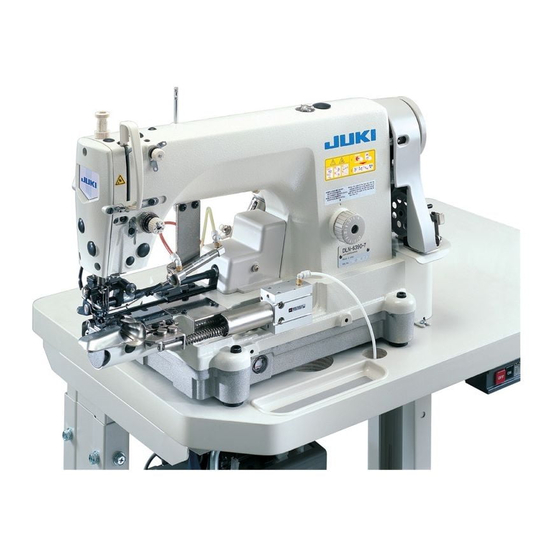
JUKI DLN-6390 Engineer's Manual
High-speed, 1-needle, cylinder-bed, needle-feed, lockstitch machine with large hook; high-speed, 1-needle, cylinder-bed, needle-feed, lockstitch machine with automatic thread trimmer and large hook
Hide thumbs
Also See for DLN-6390:
- Instruction manual (380 pages) ,
- Handbook (257 pages) ,
- Specifications (4 pages)
Table of Contents
Advertisement
Quick Links
Advertisement
Table of Contents

Related Manuals for JUKI DLN-6390


Summary of Contents for JUKI DLN-6390
- Page 1 High-speed, 1-needle, Cylinder-bed, Needle-feed, Lockstitch Machine with Large Hook DLN-6390 High-speed, 1-needle, Cylinder-bed, Needle-feed, Lockstitch Machine with Automatic Thread Trimmer and Large Hook DLN-6390-7 ENGINEER’S MANUAL 40011375 No.E356-00...
- Page 2 PREFACE This Engineer’s Manual is written for the technical personnel who are responsible for the service and maintenance of the machine. The Instruction Manual for these machines intended for the maintenance personnel and operators at an apparel factory contains operating instructions in detail. And this manual describes “Standard Adjustment”, “Adjustment Procedures”, “Results of Improper Adjustment”, and other important information which are not covered by the Instruction Manual.
-
Page 3: Table Of Contents
CONTENTS 1. OUTLINE ......................1 (1) Features ..........................1 (2) Specifications ........................1 (3)Application .......................... 1 2. OPERATION ...................... 2 (1) Names of each components ....................2 (2) Matters to be checked before operation and trial run ............2 3. THREAD TRIMMING ..................3 (1) Principle of thread trimming .................... - Page 4 7. TROUBLES AND CORRECTIVE MEASURES..........37 (1) With regard to mechanical components ................37 (2) With regard to sewing ...................... 41 8. DRAWING OF TABLE ..................47...
-
Page 5: Outline
2) The forced lubrication system of JUKI lockstitch machine system is incorporated in the face plate section and the hook, and the reliability is improved by stable lubrication. In addition, the forced lubrication mechanism by the plunger pump is equipped to the face plate section and the hook section, and oil leakage is prevented at the time of sewing. -
Page 6: Operation
2. OPERATION (1) Names of each components 1 Needle feed dial 2 Hemming binder 3 Hemming binder cylinder 4 Oil reservoir 5 Oil gauge 6 Gear cover 7 Wiper 8 Thread tension No. 1 9 Thread tension controller (asm.) (2) Matters to be checked before operation and trial run (Matters to be checked) 1) Check whether wiring is securely performed to the control box. -
Page 7: Thread Trimming
3. THREAD TRIMMING (1) Principle of thread trimming 1. Blade point of the hook scoops needle thread. 2. Needle thread crosses over the hook. 3. Moving knife handles needle thread 4. Needle thread is caught with the thread draw-out plate (travels backward). -
Page 8: Standard Adjustment
4. STANDARD ADJUSTMENT (1) Adjusting the height of the needle bar Standard Adjustment (2) Hook timing Standard Adjustment 0 to 0.06 mm 0.8mm... - Page 9 Adjustment Procedures Results of Improper Adjustment 1) Turn the handwheel to bring the needle bar to the lowest position ™Thread breakage will be caused of its stroke, and loosen setscrew 1 in the needle bar bracket. even when the height of the 2) Set needle bar height gauge 2 supplied with the machine as needle is excessively high or accessories to installing plane 3 of the throat plate as shown...
-
Page 10: Adjusting The Needle Stop Position
(3) Adjusting the needle stop position Standard Adjustment... - Page 11 Adjustment Procedures Results of Improper Adjustment 1. Stop position after thread trimming 1) The standard needle stop position is the position where pointer A on the machine arm aligns with white marker dot B on the handwheel. (Main shaft timing : 57.5˚) 2) Stop the needle at UP position, and loosen screw 1 to perform adjustment within the range of the slot.
-
Page 12: Checking And Adjusting The Receding Position Of The Moving Knife
™ Wiring diagram of pneumatic and electric components Normal wiring Gray Black OPTION B S. M. F. L. DLN-6390-7 main unit Moving knife receding amount at the time of checking cam timing Gray Black OPTION B S. M. F. L. - Page 13 Adjustment Procedures Results of Improper Adjustment 1) Make sure that the power to the sewing machine is turned OFF. ™ Thread trimming failure will occur 2) Remove setscrews 1, setscrews 2 and setscrews 3. Then remove when the receding position of hemming binder 4, auxiliary throat plate 5 and throat plate 6.
-
Page 14: Removing/Installing The Knife Unit
(5) Removing/installing the knife unit Standard Adjustment Moving play of knife unit... - Page 15 Adjustment Procedures Results of Improper Adjustment Do not remove it unless it is necessary. And, along with the change of knife assembly position, the tail end of moving knife also moves to backward, when re-adjustment of positioning is necessary to make both the units work in conformity.
-
Page 16: Checking And Adjusting The Thread Trimmer Cam Timing
(6) Checking and adjusting the thread trimmer cam timing Standard Adjustment 1. Checking the thread trimmer cam timing Moving knife waiting Correct position where position moving knife has fully receded 2. Adjusting the thread trimmer cam timing Turn cam in this direction. - Page 17 Adjustment Procedures Results of Improper Adjustment ™ Thread trimmer cam timing is set 1. Checking the thread trimmer cam timing The work up to steps 1) through 8) is the same as that of (4) Checking in accordance with the standard and adjusting the receding position of the moving knife.
-
Page 18: Installing The Counter Knife
(7) Installing the counter knife Standard Adjustment Center of needle To be in the center Installing plane (8) Replacing the moving knife Standard Adjustment... - Page 19 Adjustment Procedures Results of Improper Adjustment 1) The correct installing position of counter knife 1 is that the ™ When the position of counter knife 1 is excessively moved to distance from the center of the needle to the blade tip of counter knife 1 is 4.5 mm and that the eyelet of moving knife 2 is side B, thread trimming failure (slip-off of needle thread at the...
-
Page 20: Disk Rising Amount Of The Thread Tension Controller (Asm.)
(9) Disk rising amount of the thread tension controller (asm.) Standard Adjustment (10) Adjusting the clutch plate and the thread trimmer magnet Standard Adjustment Section A... - Page 21 Adjustment Procedures Results of Improper Adjustment 1) How to check the floating amount of the disk of thread tension controller (asm.) When checking the receding amount of the moving knife and the cam timing in (4) Checking and adjusting the receding position of the moving knife, connector Y (black cord) in the wiring diagram of pneumatic and electric components is inserted to the place of Z.
-
Page 22: Adjusting The Driving Arm Stopper
(11) Adjusting the driving arm stopper Standard Adjustment To align (12) Replacing the synchronizer and adjusting the position of the handwheel Standard Adjustment 1±0.2mm... - Page 23 Adjustment Procedures Results of Improper Adjustment Original position of the driving arm stopper 1 Press down the roller arm 3 at the timing when going up to the tip of needle 1 almost aligns with top surface 2 of the throat plate, to make roller 7 is tightly fixed with a thread trimmer cam 8.
-
Page 24: Adjusting And Assembling The Needle Feed Adjustment Mechanism
(13) Adjusting and assembling the needle feed adjustment mechanism Standard Adjustment Clearance 2mm Screw No. 2 Center !5 5 To come in contact with each other... - Page 25 Adjustment Procedures Results of Improper Adjustment Assembling the needle feed adjusting link 1 Fix fulcrum shaft 2 on the handwheel side with setscrew 3 at the position where the clearance provided between the end plane on the handwheel side of needle feed adjusting link 1 and the machine frame is 2 mm.
-
Page 26: Adjusting And Assembling The Needle Feed Mechanism
(14) Adjusting and assembling the needle feed mechanism Standard Adjustment No screw on window Chamfering aligns with end plane. plate side Center Detail drawing... - Page 27 Adjustment Procedures Results of Improper Adjustment ™ Torque turns heavy if needle bar 1) Assembling the needle feed shaft 1 Position the lateral position of needle feed shaft 1 with thrust collars 3 so that 7 is operated without fightening the end plane of needle feed shaft arm (rear) 2 aligns with the chamfering of the needle clamp screw !7 .
-
Page 28: Assembling The Reduction Gear
(15) Assembling the reduction gear Standard Adjustment Operator’s side Antioperator’s side Eccentric direction : operator’s side Eccentric direction : antioperator’s side (Selection) Plane A Alignment of edges (Selection) - Page 29 Adjustment Procedures Results of Improper Adjustment 1) The reduction gears inside the machine arm are composed of four gears (A, B, C and D). ™ Reduction gear A : Gear attached to main shaft !0 (Screw No. 1 is set to the flat section.) ™...
-
Page 30: Adjusting The Belt Tension
(16) Adjusting the belt tension Standard Adjustment 10 to 15 mm (17) Removing/installing the oil reservoir Standard Adjustment... - Page 31 Adjustment Procedures Results of Improper Adjustment 1) Put belt 1 on handwheel 2 of the sewing machine. ™ When the belt tension is 2) Turning handwheel 2 of the sewing machine, put one side of excessively high the belt 1 on motor pulley 3. 1.
-
Page 32: Adjusting The Position Of The Hemming Binder Cylinder
(18) Adjusting the position of the hemming binder cylinder Standard Adjustment Clearance of 2 mm (19) Installing the presser Standard Adjustment Bottom surface becomes almost flush at overlapped To make top end of presser foot section and cloth is pressed by the whole bottom come in contact with presser surface in the normal state. - Page 33 Adjustment Procedures Results of Improper Adjustment 1) Assemble hemming binder cylinder 1 so that the clearance provided between the end plane of shaft 2 of the hemming binder and cylinder cap 3 is 2 mm. * The aim of open amount of the binder is 13 mm. (Caution) If the clearance is excessively small, top end 4 of the guide section in the rear face of the binder comes in contact with groove 5 in the base plate,...
-
Page 34: Bobbin Case
(20) Bobbin case Standard Adjustment 1) Adjusting pressure of idle-protection spring Change height of this section. 2) Setting bobbin into the bobbin case Direction of rotation of bobbin... - Page 35 Adjustment Procedures Results of Improper Adjustment For DLN-6390 Series, bobbin case with idle-protection spring is used. Perform the points below to adjust the pressure of the idle prevention spring. Increase the pressure of idle- When bobbin runs idle. protection spring.
-
Page 36: Adjusting Sewing
(21) Adjusting sewing 1) Return amount of the hook (hook timing) The aim of the return amount of the hook of the machine is 1.8 mm. Use the gauge supplied as accessories and adjust the return amount of the hook according to 4. - (2) Hook timing. - Page 37 6) Installing position of the arm thread guides A and C For arm thread guides A 1 and C 2, the aim is the position where the engraved marker line aligns with the center of setscrew. Engraved marker line aligns with center of screw.
-
Page 38: Setting Of Sc-380
5. SETTING OF SC-380 It is necessary to set the following settings after set-up of SC-380 to use SC-380 with DLN-6390-7. Contents of setting varies according to the version of SC- 380. Perform setting after checking the English letter indicated at the end of serial No. - Page 39 After executing the setting, perform the change of setting of each mode below. End of serial No. Mode Description Symbol “A or B” “C” 4200 / 4500 P mode Max. speed 250 / 500 600 / 500 Slow-start speed Number of stitches of slow-start 2 / 1 Thread trimming mode J1 / PRG...
-
Page 40: Maintenance
6. MAINTENANCE (1) How to sharpen the knife 1. The shape of the blade tip of counter knife 1 affects most the sharpness of the knife. In many cases, the sharpness becomes good only by sharpening of counter knife 1. 2. -
Page 41: Troubles And Corrective Measures
7. TROUBLES AND CORRECTIVE MEASURES (1) With regard to mechanical components Cause (1) Cause (2) Corrective measures Troubles 1. Stitch skipping of 1 to 1-1) Needle thread remaining on 1)-A Needle thread path is Check the inside of needle thread paths s e v e r a l s t i t c h e s the needle tip after thread abnormal and needle... - Page 42 Cause (2) Cause (1) Corrective measures Troubles From the previous page 1-4) Length of bobbin thread at 4)-A Bobbin runs idle and end Increase the spring pressure of idle- the start of sewing is too of bobbin thread is drawn protection spring.
- Page 43 Cause (2) Cause (1) Corrective measures Troubles From the previous page 1)-D There is a scratch on Correct the scratch with buff or replace the knife thread guide, moving part. knife, hook, or thread draw- out, and trimming on the way occurs.
- Page 44 Cause (2) Troubles Cause (1) Corrective measures 6. Bobbin thread is not 6-1) Receding amount of moving 1)-A Needle thread only is Correct the receding amount of moving cut. (Needle thread knife is insufficient. caught when moving knife according to 4-(4). is cut.) knife returns.
-
Page 45: With Regard To Sewing
(2) With regard to sewing Cause (2) Troubles Cause (1) Corrective measures 1. Stitch skipping 1-1) Needle components 1)-A Needle is bent. Replace the needle. 1)-B Installation of needle is Install the needle again. wrong. (Orientation or insufficient insertion) 1)-C Blunt of needle tip Replace the needle. - Page 46 Cause (2) Cause (1) Corrective measures Troubles From the previous page 5)-A Threading is wrong. 1-5) Thread path components. Check the threading according to the Instruction Manual. 1-6) Flopping of cloth. 6)-A Presser is rising. Check the presser lifting base according to the Instruction Manual.
- Page 47 Cause (2) Cause (1) Corrective measures Troubles From the previous page 3-2) Thread tension components 2)-A Needle thread tension is Decrease the tension. too high (excessively tightened). 2)-B Tension of thread tension Adjust the tension to such an extent that No.
- Page 48 Cause (2) Cause (1) Corrective measures Troubles Replace the needle with a proper one. 5. Balloon stitch 5-1) Needle components 1)-A K i n d o f n e e d l e i s SCHMETZ UY180GVS is recommended. Irregular stitches improper.
- Page 49 Cause (2) Cause (1) Corrective measures Troubles From the previous page 3)-A Scale of needle feed 5-3) Needle feed components Adjust the scale of needle feed dial to the dial is not adjusted to needle feed amount corresponding to the the needle feed cloth feed amount of the selected gear.
- Page 50 MEMO...
-
Page 51: Drawing Of Table
8. DRAWING OF TABLE Part No. : 40004480 4 x Ø3.5 on the bottom surface, depth 20 Ø16, drilled hole 240.5 2 x Ø3.5 on the bottom surface, drilled hole 10 Installing position of stopper for drawer (on the bottom surface) (126) Ø40, drilled hole 7 x Ø3.5,... - Page 52 FAX : (81)3-3430-4909 • 4914 • 4984 The description covered in this engineer's manual is subject to change for improvement of the TELEX : J22967 commodity without notice. Copyright c 2003 JUKI CORPORATION. All rights reserved throughout the world. 03 · 08 Printed in Japan (E)
Need help?
Do you have a question about the DLN-6390 and is the answer not in the manual?
Questions and answers