
Subscribe to Our Youtube Channel
Related Manuals for Icom iC-F5012


Summary of Contents for Icom iC-F5012
- Page 1 Limited functions only INSTRUCTION MANUAL VHF MOBILE TRANSCEIVER iF5012 UHF MOBILE TRANSCEIVER iF6012...
-
Page 2: Explicit Definitions
F6012 UHF MOBILE TRANSCEIVER. NOTE of personal injury, fire or electric shock. Icom, Icom Inc. and the Icom logo are registered trademarks of Icom Incorporated (Japan) in Japan, the United States, the United King- dom, Germany, France, Spain, Russia and/or other countries. -
Page 3: Precautions
Other microphones performance when used with an Icom transceiver. have different pin assignments and may damage the trans- Icom is not responsible for the destruction or damage to an ceiver. Icom transceiver in the event the Icom transceiver is used with... -
Page 4: Table Of Contents
TABLE OF CONTENTS IMPORTANT ................i 3 CONNECTION AND MAINTENANCE ....14–16 EXPLICIT DEFINITIONS ............i ■ Rear panel connection ..........14 PRECAUTIONS ..............ii ■ Supplied Accessories ..........15 TABLE OF CONTENTS ............iii ■ Mounting the transceiver ..........15 ■ Antenna ..............16 1 PANEL DESCRIPTION ..........1–6 ■... -
Page 5: Panel Description
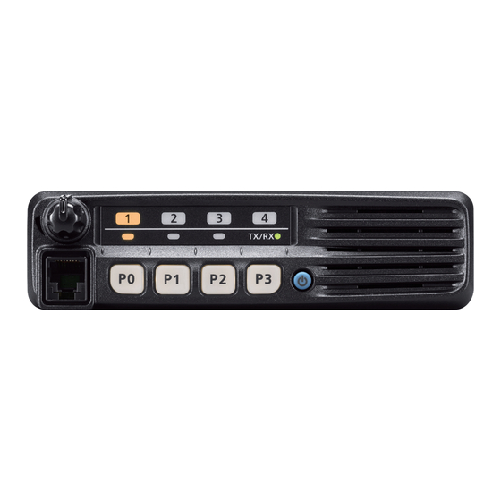
PANEL DESCRIPTION ■ Front panel Function LED (p. 2) Speaker TX/RX q AF VOLUME CONTROL KNOB [VOL] r POWER KEY [ ] Rotate the knob to adjust the audio output level. Push to turn the power ON or OFF. • Minimum audio level is pre-set. (p. 10) •... -
Page 6: Function Led
PANEL DESCRIPTION ■ Function LED D MICROPHONE The supplied or optional microphone has a PTT switch and a hanger hook. • The following functions are available when the microphone is ON or OFF hook (depending on the preprogramming): - Automatic scan start when you put it ON hook. TX/RX - Scan is cancelled when you take it OFF hook - Scan is paused when you take it OFF hook... -
Page 7: Programmable Function Keys
[P3] programmable function keys. ➥ To rewrite the operating channel as Priority A or Priority Consult your Icom dealer or system operator for details con- B, hold down [Prio A (Rewrite)] or [Prio B (Rewrite)] for cerning your transceivers programming. - Page 8 PANEL DESCRIPTION ■ Programmable function keys (continued) LOCK KEY DTMF AUTODIAL KEY Hold down to electronically lock all programmable keys ex- Push to transmit a DTMF code. cept the following: RE-DIAL KEY [Moni(Audi)], [Lock], [Call] (incl. Call A and Call B), [Emer- Push to transmit the last-transmitted DTMF code.
- Page 9 PANEL DESCRIPTION SURVEILLANCE KEY USER SET MODE KEY Push to turn the surveillance function ON or OFF. ➥ Hold down for 1 second to enter the User Set mode. When this function is turned ON, the beeps do not sound •...
- Page 10 PANEL DESCRIPTION ■ Programmable function keys (continued) Ext. CH Sel Mode KEY Push to turn the Ext. CH Select function ON or OFF. When the function is turned ON, memory channels can be selected with external input operation only. When the function is turned OFF, memory channels can be selected with [CH Up] or [CH Down] operation, or with exter- nal input operation.
-
Page 11: Basic Operation
BASIC OPERATION ■ Turning ON the power ■ Channel selection q Push [ ] to turn ON the power. There are several methods to select channels, and they may w If the transceiver is programmed for a start up password, differ, depending on your system set up. -
Page 12: Call Procedure
BASIC OPERATION ■ Call procedure ■ Receiving and transmitting Receiving: When your system employs tone signaling (excluding CTCSS and DTCS), a call procedure may be necessary prior to voice q Hold down [ ] for 1 second to turn ON the power. transmission. -
Page 13: D Transmitting Notes
BASIC OPERATION D Transmitting notes D DTMF transmission • Transmit inhibit function If the transceiver has a key assigned to [DTMF Autodial], the The transceiver has several inhibit functions which restrict automatic DTMF transmission function is available. transmission under the following conditions: - The channel is in the ‘Inaudible’... -
Page 14: User Set Mode
BASIC OPERATION ■ User Set mode r Push [P0] several times to select the appropriate item, The User Set mode can be accessed with the ‘Power ON’ then push [P2] or [P3] to set the desired level or setting. function. In this case, all set mode items are selectable. •... -
Page 15: Scrambler Function
BASIC OPERATION ■ Scrambler function ■ Priority A channel selection The Voice Scrambler function provides private communica- When one of the following operations is performed, the trans- tion between stations. ceiver automatically selects the Priority A channel. The optional Rolling or Non-rolling type can be used. •... -
Page 16: Emergency Transmission
BASIC OPERATION ■ Emergency transmission D NOTES When [Emergency] is held down for the specified time pe- riod*, the emergency signal is transmitted on the specified Depending on the preprogramming, the following functions emergency channel once, or repeatedly. are automatically activated. Ask your dealer for details. When no emergency channel is specified, the call is transmit- ted on the operating channel. -
Page 17: Mdc 1200 System Operation
BASIC OPERATION ■ MDC 1200 system operation The MDC 1200 signaling system enhances your transceiver’s capabilities with PTT ID* and Emergency signaling. *When [PTT] is pushed and/or released, the transceiver transmits its own station ID. D Transmitting an Emergency Call The MDC 1200 system’s Emergency feature can be ac- cessed using the [Emergency] key (p. -
Page 18: Connection And Maintenance
CONNECTION AND MAINTENANCE ■ Rear panel connection q ANTENNA CONNECTOR e MICROPHONE HANGER Antenna Connect to an antenna. Ask your Connect the supplied micro- phone hanger to the vehicle’s dealer about antenna selection and placement. ground for microphone on/off hook functions. (See page 2) w EXTERNAL SPEAKER JACK Connect to a 4 to 8 ø... -
Page 19: Supplied Accessories
CONNECTION AND MAINTENANCE ■ Supplied Accessories ■ Mounting the transceiver The universal mounting bracket supplied with your trans- Microphone Microphone hanger Microphone ceiver also allows overhead mounting. and screw set hanger cable • Mount the transceiver securely with the 4 supplied screws to a thick surface which can support more than 1.5 kg. -
Page 20: Antenna
CONNECTION AND MAINTENANCE ■ Antenna ■ Options • OPC-1132A/OPC-347 A key element in the performance of any communication sys- dc power cable tems is its antenna. Contact your dealer for more information 2 fuse holders are attached. USE only a 20 A fuse. regarding antennas and how to install them. -
Page 21: Doc
Signature EN 300 113-2 v1.4.1 (July 2007) EN 60950-1:2006/A11:2009 DEC.2010 CE Versions of the IC-F5012 and the IC-F6012 This warning symbol indicates that this equip- which display the “CE” symbol on the serial ment operates in non-harmonised frequency number label, comply with the essential re-... - Page 22 DECLARATION OF CONFORMITY We Icom Inc. Japan 0168 1-1-32, Kamiminami, Hirano-ku Osaka 547-0003, Japan Declare on our sole responsibility that this equipment complies with the essential requirements of the Radio and Telecommunications Terminal Bad Soden 9th Feb. 2011 Equipment Directive, 1999/5/EC, and that any applicable Essential Test Place and date of issue Suite measurements have been performed.
- Page 23 Romania France Slovakia Germany Slovenia Greece Spain Hungary Sweden Iceland Switzerland Ireland Turkey Italy United Kingdom Latvia About e-marking: Detailed installation notes for Icom mobile transceivers to be fitted into vehicles are available. Please contact your Icom dealer or distributor.
- Page 24 < Intended Country of Use > A-6905H-1EU-q Printed in Japan © 2011 Icom Inc. 1-1-32 Kamiminami, Hirano-ku, Osaka 547-0003, Japan Printed on recycled paper with soy ink.
Need help?
Do you have a question about the iC-F5012 and is the answer not in the manual?
Questions and answers