Table of Contents
Advertisement
Quick Links
Advertisement
Table of Contents

Related Manuals for KVH Industries TracVision A7


Summary of Contents for KVH Industries TracVision A7
- Page 2 Welcome Page TracVision A7 Installation Guide The TracVision A7 is a state-of-the-art, actively This product must NOT be connected to stabilized antenna system that delivers live satellite any active monitor that is visible to the TV to a vehicle, even while the vehicle is moving.
- Page 3 KVH neither endorses nor otherwise sponsors any such products or services referred to herein. Patent Protection TracVision A7 is protected by EU Design #000050877-0001; US patents D493,164; 6,856,300; 6,967,619; 6,977,614; and 7,102,571. Disclaimer Every effort has been made to ensure the correctness and completeness of the material in this document.
- Page 4 Follow Instructions – Be sure to follow all installation TracVision A7 to pay full attention to traffic and instructions as detailed in this manual. road conditions could result in an accident or collision with personal injury or death resulting.
- Page 5 If you have any comments regarding this manual, please e-mail them to manuals@kvh.com. Your Activation Department feedback is greatly appreciated! Once the TracVision A7 system is installed, the user needs to activate the receiver by calling KVH’s Activation Department: 1-866-551-8004...
-
Page 6: Table Of Contents
Table of Contents Table of Contents Getting Started ....1.1 Installing the Receiver ... . .3.1 Using this Manual . -
Page 7: Getting Started
Getting Started 1 Getting Started This section provides a basic overview of this manual and the TracVision A7 system. It also lists the items you will need to complete the installation. Contents Using this Manual ......1.3 System Overview . -
Page 8: Using This Manual
Related Documentation The following additional documents are provided This manual provides complete instructions for with the TracVision A7 system: installing the TracVision A7 system. Throughout this manual, important information is marked for your Document Description attention by the following icons: Receiver User’s Guide... -
Page 9: System Overview
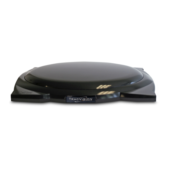
TracVision A7 System Diagram (Typical Installation) KVH strongly recommends that a KVH-authorized TracVision A7 Antenna technician and an assistant install the TracVision A7 system. Installers should have experience installing electronic equipment on a vehicle and have knowledge about satellite television. - Page 10 Getting Started System Components Receiver The receiver, mounted The TracVision A7 includes the following inside the vehicle, components: decodes satellite Antenna Unit signals from the antenna unit and sends the signals to the vehicle’s The antenna unit, mounted on the vehicle’s roof, audio/video system.
-
Page 11: Inspect Parts And Get Tools
TracVision A7 Installation Guide Inspect Parts and Get Tools If you use the roof mount kit: • Fasteners suitable for attaching the four metal 1. Unpack the box and ensure it contains everything mounting plates to the vehicle’s roof shown on the antenna and receiver Contents •... -
Page 12: Prepare The Activation Card
KVH serial numbers: activated in order to watch satellite TV via Antenna Serial Number Receiver Serial Number the TracVision A7 system. Installer: Please place antenna serial number in box above. 2. The KVH representative will provide you with 4 ID numbers necessary for activation. -
Page 13: Installing The Antenna
Installing the Antenna 2 Installing the Antenna This section explains how to mount the antenna to the vehicle and how to connect and route the antenna cable. Contents Remove the Shipping Restraints ....2.3 Mount the Antenna - Rack Mount Kit . -
Page 14: Remove The Shipping Restraints
Installing the Antenna Remove the Shipping Restraints Cut and remove all of the shipping restraints from Removing the Shipping Restraints underneath the antenna. To remove the wire restraints, you will need to use heavy-duty wire cutters. Shipping Restraint Locations on Antenna Base 54-0350... -
Page 15: Mount The Antenna - Rack Mount Kit
TracVision A7 Installation Guide Mount the Antenna - 2. Position the roof rack crossbars 35 ⁄ " apart, measured center-to-center. Ensure that the Rack Mount Kit crossbars are securely fastened to the vehicle. If you are mounting the antenna to the vehicle’s roof Roof Rack Crossbars rack, follow the steps below. - Page 16 Installing the Antenna 3. With an assistant’s help, gently place the antenna 4. Each bracket contains several pairs of pegs. These onto the roof rack with the cable connector facing pegs allow you to place two rubber cushions in the rear of the vehicle. All four brackets should different positions to best fit the vehicle’s style of rest on top of the roof rack’s crossbars.
- Page 17 TracVision A7 Installation Guide 5. With the cushions installed in the brackets, the a. Remove the #8-32 x ⁄ " screws and washers bottom of the antenna should rest above the securing the factory-installed plastic spacer to vehicle’s roof. If the antenna’s base touches the the metal bracket.
- Page 18 Installing the Antenna Securing the Brackets to the Crossbars If you installed extra spacers in Step 5, and the bottom of the antenna still contacts the roof, KVH recommends that you either use Cover the roof mount option or replace the roof 2"...
-
Page 19: Mount The Antenna - Roof Mount Kit
TracVision A7 Installation Guide Mount the Antenna - 2. Place the metal mounting plates onto the vehicle’s roof (do not attach yet!). Ensure the nut Roof Mount Kit bar swivels easily within each mounting plate. If you are mounting the antenna directly to the roof,... - Page 20 Installing the Antenna 6. Make sure the antenna is positioned on the 4. With an assistant’s help, position the antenna centerline of the roof in the desired location and onto the centerline of the vehicle’s roof with a resting firmly on the mounting blocks. With the mounting block and mounting plate under each antenna in place, mark the roof along the outside bracket.
- Page 21 TracVision A7 Installation Guide Spacer Installation Instructions – If Necessary in Step 5 Adding Spacers (If Needed for Extra Height) If spacers are needed to raise the antenna off the roof, follow the steps below to install a spacer under...
- Page 22 Installing the Antenna 13. Flip down the skirt on each rubber mounting 12. At each bracket, insert two hex socket screws block to hide the mounting plates. through the antenna bracket and mounting block and into the nut bar. Be sure to use the supplied 14.
-
Page 23: Mount The Antenna - Hummer Mount Kit
TracVision A7 Installation Guide Mount the Antenna - 3. Remove the long rubber strips that run along the top of the crossbars. Be sure to save these strips Hummer ® Mount Kit for future use. If you are mounting the antenna to a Hummer roof 4. - Page 24 Installing the Antenna 8. Position the T-nuts in the crossbars so that they 6. Attach each of the four mounting brackets to the line up with the holes in the antenna mounting antenna base using two of the supplied ⁄ "-20 x ⁄...
- Page 25 TracVision A7 Installation Guide 4. Remove the long rubber strips that run along the Hummer H3 Mounting Instructions top of the crossbars. Be sure to save these strips 1. Position the roof rack crossbars 35" apart, for future use. measured center-to-center. Ensure that the crossbars are securely fastened to the vehicle.
- Page 26 Installing the Antenna 9. Position the T-nuts in the crossbars so that they 7. Attach each of the four mounting brackets to the line up with the holes in the antenna mounting antenna base using two of the supplied ⁄ "-20 x ⁄...
-
Page 27: Connect The Antenna Cable
TracVision A7 Installation Guide Connect the Antenna Cable There are two options for passing the cable into the vehicle: Now that you have mounted the antenna to the Option 1 - Through the roof vehicle’s roof, connect the supplied antenna cable... - Page 28 Installing the Antenna 3. Choose a location on the roof for the ⁄ "-diameter Option 1 - Route the Cable Through the Roof cable access hole. Inside the vehicle, remove the 1. Connect the antenna cable to the antenna. Hand- headliner to access the underside of the roof tighten, then tighten with a ⁄...
- Page 29 TracVision A7 Installation Guide 6. Set aside the backing plate, then use a ⁄ " drill bit 8. Move the fitting down the cable until it covers the to drill the three fitting mounting holes. cable access hole, flush to the vehicle’s roof. Line up the fitting’s three mounting holes with the...
- Page 30 Installing the Antenna 11. Using the supplied tie-wraps (or equivalent), 9. Secure the #6-32 x ⁄ " screws to the backing plate secure the antenna cable to the roof rack, if inside the vehicle. necessary. Backing Plate (Inside Vehicle) Securing the Cable to the Roof Rack Tie-wrap Backing Plate 10.
- Page 31 TracVision A7 Installation Guide 3. Connect the antenna cable to the antenna. Hand- Option 2 - Route the Cable Behind the Hatch tighten, then tighten with a ⁄ " wrench for ⁄ turn 1. Move the steel fitting down the length of the...
-
Page 32: Installing The Receiver
Installing the Receiver 3 Installing the Receiver This section explains how to connect all system cables to the mobile receiver and how to mount the receiver inside the vehicle. Contents Choose the Receiver Location ....3.3 Wire the Receiver . -
Page 33: Choose The Receiver Location
Installing the Receiver Wire the Receiver Choose the Receiver Location For the TracVision system to work, you will need to Now that you’ve installed the antenna, you need to connect the following cables to the receiver: find a suitable location inside the vehicle for installing the receiver. - Page 34 TracVision A7 Installation Guide TracVision A7 Wiring Diagram Antenna Black Ground Input Power (10-16 VDC) DC Power Receiver FUSE (8A) POWER (10-16V DC) Tested to comply This device complies with Part 15 of the FCC rules. Operation is subject C AU T I O N...
- Page 35 Installing the Receiver Prepare the Antenna Cable Connect the Antenna Cable The antenna cable should already be connected to the Connect the antenna cable to the “To KVH Antenna” antenna and routed to the receiver. If the cable is too jack on the receiver’s rear panel.
- Page 36 TracVision A7 Installation Guide Connect the Audio/Video Cables Connect the RF Converter Cable The receiver kit includes standard audio/video cables To connect the RF converter cable, follow the steps with RCA-type connectors for connecting the receiver below. to your vehicle’s entertainment system. The receiver 1.
- Page 37 Installing the Receiver Connect the Audio Cables Connect the Video Cable Option 1 – Standard Audio Cables Option 1 – Standard Video Cable (cables included) (cable included) Connect the red and white audio cables to the Connect the yellow video cable to the receiver’s receiver’s “Audio L”...
- Page 38 TracVision A7 Installation Guide Connect the Power Cable Now that you’ve connected all other cables to the Power Wiring (Preferred) receiver, follow the steps below to connect the power cable. FUSE (8A) POWER (10-16V DC) This device complies with Part 15 of the FCC rules. Operation is subject...
- Page 39 Installing the Receiver Connect the Power Cable to the Battery (Alternative Wiring Option, Only If Necessary) Power Wiring (Alternative Option) If you are unable to connect the receiver power cable to switched (accessory) power as described on the FUSE (8A) POWER (10-16V DC) This device complies with Part 15 of the FCC rules.
-
Page 40: Mount The Receiver
TracVision A7 Installation Guide Mount the Receiver Install Batteries in the Remote Once all cables are connected, mount the receiver The receiver comes with an RF/IR remote control. inside the vehicle. Insert two AAA batteries in the remote control’s battery compartment. Be sure to observe the correct Do not block the receiver’s ventilation... -
Page 41: Completing The Installation
Completing the Installation 4 Completing the Installation This section explains how to turn on and test the TracVision A7 system. It also lists important information the owner needs to know. Contents Post-installation Checklist ..... . .4.3 Test the System . -
Page 42: Post-Installation Checklist
Completing the Installation Post-installation Checklist Congratulations! You’ve completed the TracVision A7 installation. Before you turn on and test the system, please make certain that you have completed the following important steps: Step Page # Done? You affixed the antenna serial number label to the red Activation Card . - Page 43 TracVision A7 Installation Guide Step Page # Done? You secured the antenna to the vehicle using the supplied hardware. 2.7, 2.11, 2.13 2.15 After connecting the antenna cable to the antenna, you installed 2.17, 2.20 the rubber boot over the connector.
-
Page 44: Test The System
3. Turn on the power switch on the front of the ensure everything works properly. Follow the steps TracVision mobile receiver. below to turn on the TracVision A7 system and verify proper operation. Receiver Power Switch 1. Ensure the antenna has a clear view of the satellite. - Page 45 TracVision A7 Installation Guide 4. Wait while the antenna searches the sky for the 5. A progress bar will appear on the TV, indicating satellite. Within a few minutes, all three status that the receiver is downloading the program lights on the front of the receiver should be lit guide.
-
Page 46: Educate The Customer
Completing the Installation • The owner needs to register the system for Educate the Customer product warranty validation. Refer to the Product Registration Form for details or visit: Be sure to give the manuals to the owner and explain www.kvh.com/register. how to use the product. -
Page 47: System Specifications
System Specifications Appendix A System Specifications Physical Characteristics Environmental º º º º Power 10-16 volts DC, 50 watts Operating Temperature F to +131 F (-25 C to +55 º º º º Antenna Dimensions 30.5" wide x 5.3" high Storage Temperature F to +140 F (-29... - Page 48 KVH Industries, Inc. 50 Enterprise Center • Middletown, RI 02842-5279 U.S.A .• Phone: (401) 847-3327 • Fax: (401) 849-0045 • E-mail: info@kvh.com © Copyright 2006, KVH Industries, Inc. ® and TracVision ® are registered trademarks of KVH Industries, Inc.
Need help?
Do you have a question about the TracVision A7 and is the answer not in the manual?
Questions and answers