Advertisement
Quick Links
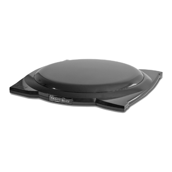
TracVision A9 Antenna
Reshipping Instructions
Technical Support
If you need technical assistance, please contact KVH Technical Support:
Phone: +1 401 847-3327
Email:
support@kvh.com
(Mon.-Fri., 9 am-6 pm; Sat., 9 am-2 pm ET, -5 GMT)
The following pages explain how to prepare a
®
TracVision
A9 antenna for reshipping.
Important!
Be sure to install the tie-wrap shipping restraints
and pack the antenna in its original packaging, as
explained in these instructions, to ensure a safe
shipment. Without the restraints, the antenna will
become damaged. Shipping damage will not be
covered under KVH's warranty policy.
Tools Required
This procedure requires the following tools:
• Phillips screwdrivers
• #2 Phillips torque screwdriver set to 21 in.-lbs
• 1/4" driver
• 1/4" hex bit, if necessary
• 5/32" torque hex driver set to 21 in-lbs
Step 1 - Remove the Mounting Brackets
a. Power off and disconnect power from the
TV-Hub to remove power from the antenna.
CAUTION
To prevent injury, be sure to disconnect all power
from the antenna before proceeding. Power must
remain disconnected for the duration of this
procedure.
b. Disconnect the RF cable from the antenna.
c. Remove the antenna from the vehicle and bring it
to a workbench suitable for service.
KVH and TracVision are registered trademarks of KVH Industries, Inc. All other trademarks are property of their respective companies.
The information in this document is subject to change without notice. No company shall be liable for errors contained herein.
© 2015 KVH Industries, Inc., All rights reserved. 54-1122 Rev. A
Figure 1: A9 Antenna
1
Advertisement

Related Manuals for KVH Industries TracVision A9


Summary of Contents for KVH Industries TracVision A9
- Page 1 KVH and TracVision are registered trademarks of KVH Industries, Inc. All other trademarks are property of their respective companies. The information in this document is subject to change without notice. No company shall be liable for errors contained herein.
- Page 2 d. Disconnect the four mounting brackets from the Figure 2: Removing the Mounting Brackets antenna by removing the two 1/4"-20 x 3/4" hex socket screws at each mounting bracket (see Figure 2). Save the mounting brackets and hardware for later. Factory-installed bolt NOTE: The factory-installed bolts, in the base of the antenna between the bracket holes, do not need to be...
- Page 3 Figure 5: Shipping Restraints #1 and #2 Figure 6: Shipping Restraint #3 Figure 7: Shipping Restraint #4 Figure 8: Shipping Restraint #5 Figure 9: Shipping Restraint #6...
- Page 4 Step 4 - Reattach the Radome and Trim Ring Figure 10: Reattach the Trim Ring and Radome a. Inspect the inside of the antenna to make sure you have not left any tools or debris inside. Trim Ring b. Reinstall the radome onto the antenna, securing it with the four 1/4"-20 screws and washers you removed earlier.
Need help?
Do you have a question about the TracVision A9 and is the answer not in the manual?
Questions and answers