Advertisement
Advertisement
Table of Contents

Related Manuals for Behringer Shark DSP110


Summary of Contents for Behringer Shark DSP110
- Page 1 Users’s Manual Version 1.2 April 2001 www.behringer.com...
-
Page 2: Safety Instructions
SHARK DSP110 SAFETY INSTRUCTIONS CAUTION: To reduce the risk of electrical shock, do not remove the cover (or back). No user serviceable parts inside; refer servicing to qualified personnel. WARNING: To reduce the risk of fire or electrical shock, do not expose this appliance to rain or moisture. - Page 3 1.1 The concept With the SHARK DSP110 you purchased a device that combines an automatic Feedback Destroyer using the ingenious search algorithms of our FEEDBACK DESTROYER PRO DSP1124P, a variable Delay Line (adjustable in msec, feet and meter), a ULN (Ultra-Low Noise) microphone pre-amp with Phantom Power, an automatic Noise Gate, a variable Low Cut filter and a Compressor—all in one ultra-...
-
Page 4: Before You Begin
If the unit is damaged, please do not return it to BEHRINGER, but notify your dealer and the shipping company immediately, otherwise claims for damage or replacement may not be granted. - Page 5 Further information can be found in chapter 3 “INSTALLATION”. As a standard the audio inputs and outputs of the BEHRINGER SHARK DSP110 are fully balanced. If possible, connect the unit to other devices in a balanced configuration to allow for maximum interference immunity.
-
Page 6: Control Elements
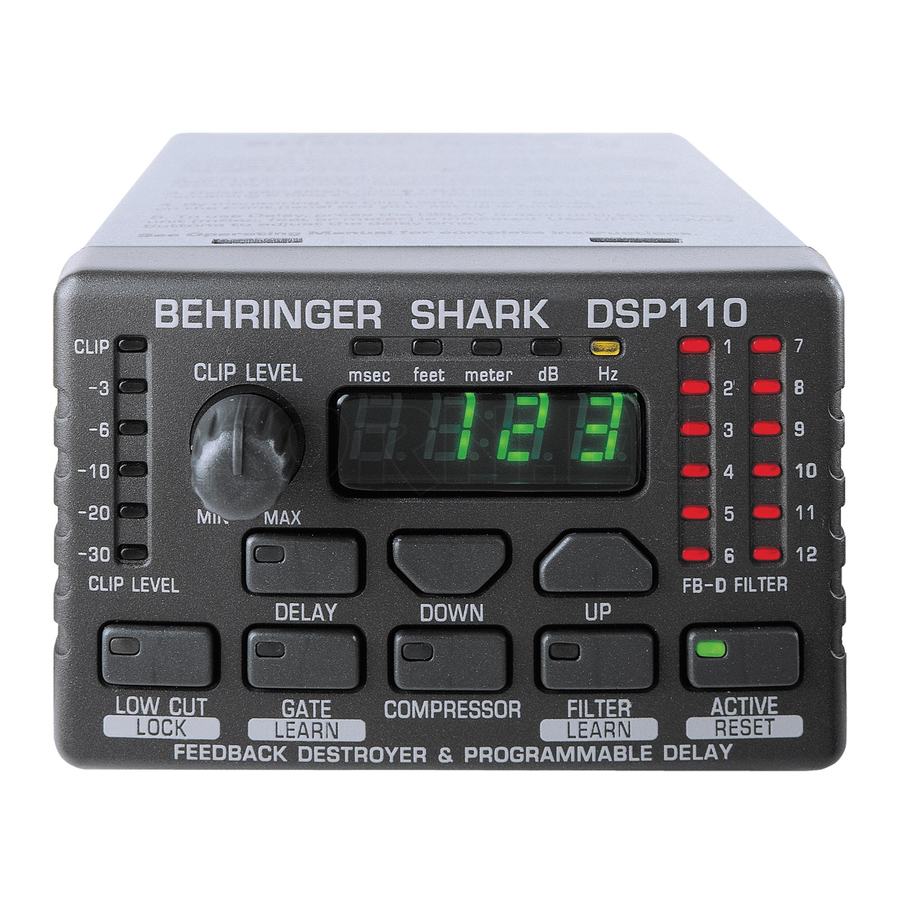
SHARK DSP110 1.3 Control elements Fig. 1.2: Front panel control elements of the DSP110 The CLIP LEVEL METER shows you whether or not the digital circuitry is driven correctly. Any corrections can be made with the CLIP LEVEL control . Be sure that the CLIP LED won’t light up. - Page 7 SHARK DSP110 The 4-digit DISPLAY reads the absolute values of the adjusted parameters. The FB-D FILTER STATUS LEDs display the status of each of the 12 individual filters. The SHARK uses four different filter modes: Disabled filters (which can be re-enabled with the ACTIVE button). When a filter is off, its LED is not lit.
- Page 8 SHARK DSP110 The LOW CUT button lets you enter the high pass filter’s cut-off frequency (20 to 150 Hz). When set to OFF the filter is inoperative. The control and “Hz” LEDs light up while you are entering a value. Use the UP/DOWN buttons to edit.
- Page 9 SHARK DSP110 When both FILTER LED and display stop flashing, the FILTER LEARN function has been completed. Press the FILTER key to cancel the function. After a short delay, the unit returns to the FILTER menu. The FILTER LEARN function generates short feedback-causing signals that are sent back to the DSP110’s input, where feedbacks are detected and...
- Page 10 SHARK DSP110 Fig 1.3: Rear panel control elements and connectors of the DSP110 This is the SHARK’s balanced XLR output. This is the SHARK’s balanced XLR input. The MIC GAIN control adjust the input signal gain, when the INPUT LEVEL switch has been pressed (position: MIC).
- Page 11 SHARK DSP110 This is the SHARK’s balanced JACK input, which is wired in parallel to the XLR input. Use the INPUT LEVEL switch to select the input sensitivity (microphone or line levels). In LINE mode, you can use the CLIP LEVEL control to adapt the internal level settings to the digital circuitry.
- Page 12 SHARK DSP110 Fig. 2.1: The SHARK connected between microphone and microphone input on console 2.1.2 Connection between line-level source and mixing console At first sight, this configuration may seem to make no sense, because line-level sources usually have no problems with feedback frequencies. However, acoustic instruments are often equipped with so-called piezo pickups which are susceptible to feedback.
- Page 13 SHARK DSP110 2.1.3 Connection between mixing console and power amplifier When you use the SHARK as a Delay Line unit for speaker systems placed at various positions (see chapter 2.3), you should connect the SHARK between the console’s output and the input of the power amp driving the “delayed” speakers.
- Page 14 SHARK DSP110 2.1.4 The SHARK used in the monitor path Inserting the DSP110 in the monitor path of your mixing console gives you utmost protection against unwanted feedback. Monitor paths are particularly susceptible to feedback, because on stage there are usually several microphones and speakers placed close to each other.
- Page 15 SHARK DSP110 Fig. 2.4: Two SHARKs in the monitor path 2.1.5 The SHARK used in single channels and subgroups Whenever you want to make sure that wanted feedback such as the feedback sounds produced by a guitar won’t be removed, you should insert one or several DSP110 into “feedback-prone”...
- Page 16 SHARK DSP110 Fig. 2.5: The SHARK in the insert path 2.1.6 Automatic “tuning in” of P.A. and monitor systems With the DSP110 you can improve the protection against feedback even before a concert begins, simply by “tuning in” your sound reinforcement system: once the system has been installed and set up, open all microphone channels and monitor paths, then enable FILTER LEARN mode on your DSP110.
- Page 17 SHARK DSP110 2.2 The Feedback Destroyer in the SHARK The SHARK identifies feedback by splitting the entire frequency spectrum (20 Hz to 20 kHz) into sections of 1/60 of an octave and determining the level of each of these bands. The values calculated are then referenced to the level of the overall signal. The resulting level difference determines whether or not a filter is set.
- Page 18 SHARK DSP110 2.3 The integrated Delay In addition to speakers on or near the stage, major-scale installations often have speaker groups positioned at a distance to the stage or flown above the audience, in order to provide listeners away from the stage with direct sound. However, since sound needs some time to travel around (343.6 m/sec at 20°C, accelerates by 0.6 m/...
-
Page 19: The Compressor Function
SHARK DSP110 between microphones, without producing any unpleasant side effects. A typical Gate application is the processing of vocal tracks. Especially when using a Compressor, the distance between microphone and singer is critical: as the distance increases, more and more disturbing background noise is picked up. Use the Gate function to fade out unwanted interference “inaudibly”... -
Page 20: Installation
3. INSTALLATION 3.1 Audio connections As standard, the BEHRINGER DSP110 is installed with electronically servo-balanced inputs and outputs. The new circuit design features automatic hum and noise reduction for balanced signals and thus allows for trouble-free operation, even at high operating levels. - Page 21 SHARK DSP110 Unbalanced use of Balanced use of mono 1/4" jack plugs stereo 1/4" jack plugs Tip = Tip = Signal hot (+ve) Ring = cold (-ve) Sleeve = Ground / Shield Sleeve = Ground / Shield Ring Sleeve Sleeve...
-
Page 22: Specifications
Net Weight approx. 0.5 kg BEHRINGER is constantly striving to maintain the highest professional standards. As a result of these efforts, modifications may be made from time to time to existing products without prior notice. Specifications and appearance may differ from those listed or illustrated. - Page 23 SHARK DSP110 5. RACKMOUNT (OPTIONAL) With the available rackmount (optional) you have the possibility to place five SHARKs on two units of space in your rack. Before you begin with the work, please disconnect the Power Supply Units from the SHARKs! To mount the SHARKs on the rackmount you should use the supplied screws (type M3).
- Page 24 SHARK DSP110 Fig. 5.1: Installation of the DSP110 on the available rackmount (optional) Please, only use the supplied screws to install the SHARKs on the rackmount. Longer or thicker screws can damage the electronics inside of the device and doing so will void your warranty rights.
-
Page 25: Warranty
BEHRINGER shall, at its sole discretion, either repair or replace the product. 6. If an inspection of the product by BEHRINGER shows that the defect in question is not covered by the warranty, the inspection costs are 2. If the warranty claim proves to be justified, the product will be returned payable by the customer.
Need help?
Do you have a question about the Shark DSP110 and is the answer not in the manual?
Questions and answers