Table of Contents
Advertisement
Quick Links
Advertisement
Table of Contents

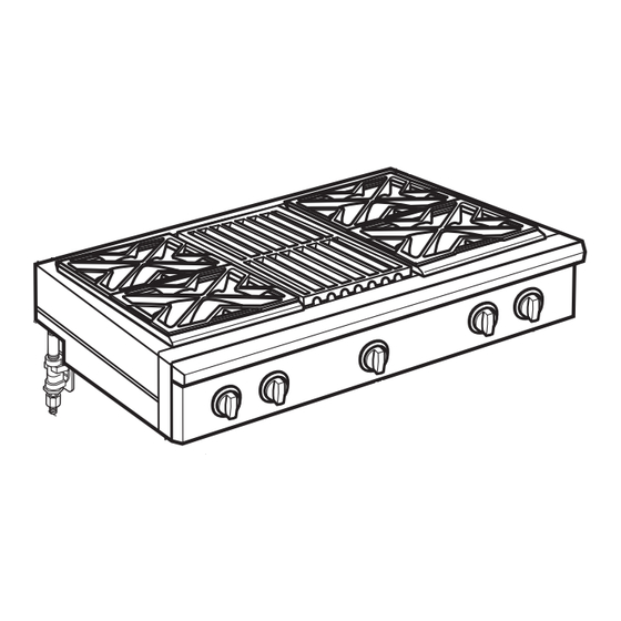
Summary of Contents for GE 36” Rangetop
- Page 1 Installation Instructions 36” Rangetop 49-85219 06-14 GE...
-
Page 2: Safety Information
Safety Information BEFORE YOU BEGIN Vent hood Combinations: Read these instructions completely and carefully. It is recommended that these rangetops be installed IMPORTANT in conjunction with a suitable overhead vent hood. • Save these instructions for ” • Install a hood with at least 1200 CFM above a 48 local inspector’s use. -
Page 3: Table Of Contents
Design Information CONTENTS Installation Instructions Design Information Step 1, Cut the Countertop Opening ......9 Models Available ..............3 Step 2, Install the Rangetop ..........10 Backsplash Accessories ............3 Step 3, Connect Rangetop to Gas ........10 Product Dimensions and Clearances for 48” Wide Models ...............4 Step 4, Connect Electrical ..........11 Step 5, Check Burners ............11 Product Dimensions and Clearances... -
Page 4: Product Dimensions And Clearances For 48" Wide Models
Design Information PRODUCT DIMENSIONS AND CLEARANCES FOR 48” MODELS 27-1/2” to Universal Utility Locations Front of ” 47-7/8 Width Bullnose 2” Locate gas 17” inlet on back 8-1/2” wall or on 16” Height floor 2” from back wall. 48” Minimum 12”... -
Page 5: Product Dimensions And Clearances For 36" Wide Models
Design Information PRODUCT DIMENSIONS AND CLEARANCES FOR 36” MODELS Universal Utility Locations 27-1/2” to ” 35-7/8 Width Front of Bullnose 2” Locate gas 17” inlet on back wall or on 16” 8-1/2” floor 2” from Height back wall. 48” Minimum 12”... -
Page 6: Installation Options
Design Information INSTALLATION OPTIONS Finished back edge † 8” of control panel Countertop Level Back edge of chamfer Include the overhang of the rear trim when countertop continues behind the product. † The overhang is decorative only. The weight of the rangetop is fully supported by the side trims. ** Maximum countertop cutout depth * Minimum cabinet cutout depth from the back of the rear trim to the back... -
Page 7: Installation Preparation
Installation Preparation TOOLS REQUIRED MATERIALS PROVIDED Drill and Regulator Hold-Down Appropriate Bits Saber Saw Strap Adjustable Wrench Measuring Tape MATERIALS REQUIRED (not provided) 1/4” Driver or Wrench Carpenter’s Square Joint Pipe Fittings Shut-Off Sealant Valve Safety Glasses 5-foot maximum length, 5/8” O.D. CSA-approved flexible metal gas supply Phillips #2 Screwdriver... -
Page 8: Remove Packaging
Installation Preparation REMOVE PACKAGING • Cut the ties holding the grill grate to the grill frame. CAUTION Griddle Flue Cover Stand clear. The ends of the cut metal banding may snap toward you. • Cut the metal banding. • Remove packaging tape and foam. Dispose of packaging materials properly. -
Page 9: Step 1 Cut The Countertop Opening
Installation CUT THE COUNTERTOP OPENING STEP 1 48” wide models are designed to fit in 48” or wider base cabinets 36” wide models are designed to fit in 36” or wider base cabinets Cutout Opening with False Bottom Measure carefully when cutting the countertop. Make sure sides of the opening are parallel. -
Page 10: Step 2, Install The Rangetop
Installation INSTALL RANGETOP STEP 2 • Slide the rangetop into the opening. Make sure the rangetop is evenly seated and supported. • A hold-down strap with screws is provided to secure the rangetop to the rear or side cabinet walls. Hold-Down Strap •... -
Page 11: Step 4 Connect Electrical
Installation CONNECT ELECTRICAL STEP 4 FINALIZE INSTALLATION • Plug power cord into properly grounded Place the burner grates over the burners. The receptacle. grates should be seated and should not rock. • Press the button on the left side of the control The griddle is secured with screws. -
Page 12: Install The Rangetop Backsplash Accessory
ZX12B30PSS, ZX12B36PSS, ZX12B48PSS Accessory Installation ” HIGH BACKSPLASH WARNING: INSTALL 12” BACKSPLASH WARNING: To prevent ignition of combustible materials, This backsplash must be the entire back wall above the range must be securely fastened to the wall. Failure to do protected by a backsplash constructed of non- so could result in damage or personal injury. -
Page 13: Install The Adjustable Backsplash Accessory
ZXADJB30PSS, ZXADJB36PSS, ZXADJB48PSS Accessory Installation ” TO 36” ADJUSTABLE BACKSPLASH (not included) INSTALL THE WALL SUPPORT PANELS WARNING: WARNING: To prevent ignition of combustible materials, The wall support panels the entire back wall above the range must be must be securely fastened to the wall. Failure to protected by a backsplash constructed of non- do so could result in damage or personal injury. - Page 14 ZXADJB30PSS, ZXADJB36PSS, ZXADJB48PSS Accessory Installation INSTALL COVER PANELS INSTALL COVER PANELS (cont.) See alternate method if side access is blocked. ALTERNATE METHOD: When side access is blocked • Install bottom cover over the bottom support while • Hold the bottom cover over the bottom support while driving one screw (provided) into each side.
- Page 15 Installation Convert Natural Gas to LP Gas Operation Instructions Convert LP Gas to Natural Gas Operation 2 CONVERT THE REGULATOR WARNING: This conversion must be Disconnect all electrical power at the main circuit performed by a qualified installer or gas supplier in breaker or fuse box.
-
Page 16: Gas Conversion
Installation Instructions for Gas Conversion 3 CHANGE BURNER ORIFICES (cont.) 4 ** CHANGE GRILL ORIFICE (cont.) IMPORTANT: Find your model number below. Read A. Remove the grill cover, each orifice label to identify and install them in the grates and grate frame. Lift exact locations shown. - Page 17 Installation Instructions for Gas Conversion 5 CHANGE GRIDDLE ORIFICE 6 ADJUST BURNER FLAMES (if present) Locate the 3/4” long griddle orifice. Normally, burners do not need further adjustment. Select for your gas type. LP .047, NAT .076 Make adjustments only when necessary. A.
- Page 18 Notes...
- Page 19 Notes...
- Page 20 Notes...


Need help?
Do you have a question about the 36” Rangetop and is the answer not in the manual?
Questions and answers