Advertisement
Quick Links
Advertisement

Related Manuals for Channel Master Off-Air Antenna


Summary of Contents for Channel Master Off-Air Antenna
- Page 1 Off-Air Antenna Installation Guide Solutions For The Professional Installer...
- Page 2 INTRODUCTION All Channel Master VHF/FM and UHF/VHF/FM he information in this manual has been antennas have sensitivity classifications such as gathered from some of the most experienced antenna installation professionals in the “fringe,” “suburban,” “deep fringe,” etc. These classi- fications are designed to indicate at what distance country and compiled by Channel Master ®...
- Page 3 CHAPTER ONE: A NTENNA ELECTION asically, a receiving antenna is a device for VHF/FM antennas. The wider variety of UHF designs (Figure 1-3) is possible because they don’t require the intercepting the electromagnetic waves or signals, sent from a transmitter. Some antennas long elements that VHF/FM antennas do.
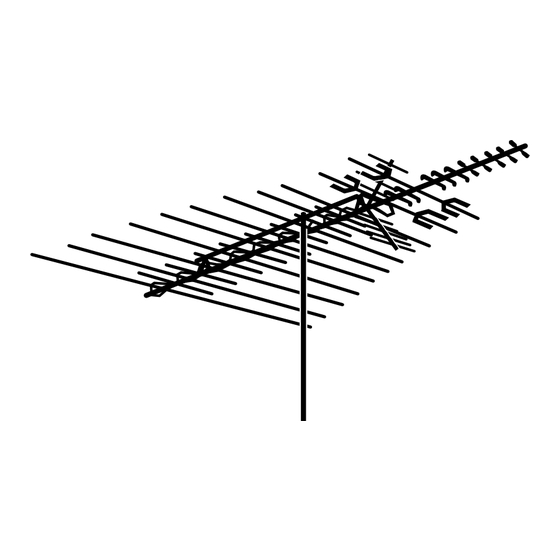
- Page 4 Fig. 1-2. A VHF/FM broadband TV antenna. Fig. 1-1. The principal parts of a basic Yagi-type TV antenna. Fig. 1-6. FM antenna. Fig. 1-3. Various designs of UHF TV antennas. ® ® Fig. 1-5. Channel Master CROSSFIRE UHF/VHF/FM TV antenna. Channel Master ® SMARTenna ®...
- Page 5 If you are in doubt about the amount of gain required, An antenna with a relatively narrow beamwidth select an antenna that is slightly larger than you think generally is best suited for areas where interference is actually needed. The performance of all from sides is a problem.
-
Page 6: Safe Installation
CHAPTER TWO: S NSTALLATION ROCEDURES here are extremely important safety factors to 12. Carry a well-equipped first aid kit in your truck. consider. Learning and following simple safety precautions can, quite literally, save your life. Following safe procedures also helps prevent costly 13. - Page 7 CHAPTER THREE: M OUNTING PTIMUM IGNAL TRENGTH deally, an antenna should be mounted at the point where the signals are the strongest, though often this is impractical or impossible. Also, the antenna should be mounted where it can be easily serviced Fig.
- Page 8 Antenna output signals of 500 uV and above are con- sidered adequate. Any signal level below 1,000 uV will require preamplification. To use the field-strength meter, orient your test antenna in the direction of incoming signals and activate the meter. To orient the actual installed antenna in an area where several channels are coming from the same general direction, aim the antenna to obtain the highest reading with the field-strength...
- Page 9 CHAPTER FOUR: T OOLS, ASTS & ARDWARE EQUIREMENTS Tools The majority of the tools and equipment you will need for most installations are apparent. The following is a list of useful tools and miscellaneous materials that might also come in handy. 1.
- Page 10 MOUNTING SITES AND RELATED PROCEDURES Attic Installations An attic installation (Figure 4-3) may work in areas where strong signals are present. In most cases, an attic installation is the easiest, fastest, most Fig. 4-4. Fig. 4-5. economical, and most convenient installation. There Examples of swivel mounts that can be used in attic installations.
- Page 11 Chimney Mounts centered on the bricks – not over the mortar joint. Pull each strap tight, line it up so that it is level, and Chimney Mounts (Figure 4-7) are used more frequent- then tighten it just enough to hold it in place. ly than other types of mounts, but they often are not the best option.
- Page 12 However, if cost savings or limited space require it, a properly guyed base mount will usually work. Unlike a chimney mount, a base mount holds the mast at only one point, the bottom. Consequently, the mast also must be supported by guy wires, regardless of the mast length.
-
Page 13: Wall Mounts
Wall Mounts Many types of wall mount brackets are available. However, many of them are poorly made and will not withstand more than a moderate wind. Buy only the best quality wall mount brackets (Figure 4-12). When installing a wall mount, space the brackets as far apart as possible (or practical). - Page 14 Firmly clamp the antenna to the upper end of the chimney or wall mounts. However, because ground mast. Insert the mast into the base hole or rest it on and roof mounts do provide bottom support, the deck or patio. Vertically position the mast by telescoping masts can be used with these mounts “walking”...
- Page 15 Vent Pipe Mounting Vent pipe mounting (Figure 4-16) secures the antenna and mast to the plumbing (gas) vent that comes up through the roof of the house. This type of mounting should be used only for the smallest antennas, and then only when economy absolutely demands it.
- Page 16 CHAPTER FIVE: S ELECTING & NSTALLING RANSMISSION Selecting and Installing Transmission Line Transmission line or downlead, is the wire that carries the signal from the antenna output terminals to the receiver input terminals. Even the best antenna and the most expensive receiver will not produce an acceptable picture if the transmission line has not been carefully selected and correctly installed.
- Page 17 indoors, drive staples or tacks only in the center portion of the insulation between the conductors. Do not use any staples or tacks large enough to “bridge” the conductors. This will short the conductors. Run twinlead directly to the back of the set from the wall, floor, or baseboard.
- Page 18 Fig. 5-7. A weather boot installed over the output connections of an antenna. Aluminum/mylar-equipped coaxial TV cable provides superior low-loss performance. (Examples are Channel Master coaxial cable model numbers 9533, GENERAL GUIDELINES FOR INSTALLING 9539, 9540, and 9544.) TRANSMISSION LINE...
- Page 19 Note: Always make a drip loop (Figure 5-9) at the There are various couplers, amplifiers, and wall entry point so that water will run off the line and not outlets that are useful in many installations. Because into the house. these devices usually...
- Page 20 CHAPTER SIX: G ROUNDING ROCEDURES he National Electrical Code (NEC) requires that every antenna installation be grounded. Also many areas have local antenna-grounding codes. Be sure that you are familiar with all of the grounding and other antenna regulations in your area.
- Page 21 (The 18 gauge wire is recommended for high-wind areas and installations over 20 ft. above the uppermost support.) Fig. 7-2. Channel Master Galvanized Steel Wire Model 9080. Standard antenna masts (10 feet in height) require Fig. 7-3. The correct positions of the guy wires in a only one set of three guy wires (Figure 7-3).
- Page 22 The guy wires are attached to the upper half of each The final tightening of the guy wires is accomplished mast section with guy ring and clamp. The ring and by rotating the turnbuckles with a screwdriver. Do clamp are fitted to the mast before the antenna is not make the wires too tight;...
- Page 23 An example is Channel Master Rotor the desired channel’s transmitting tower, or in the Wire Model No. 9554.) All Channel Master antenna direction that provides optimum reception of a rotors use 3 conductor rotor wire. To attach the rotor particular channel.
- Page 24 Fig. 8-3. Connecting the rotor wire to the drive unit of the rotor. The “reference wire” is either wider or is a different color than the other conductors. Connect it to terminal No. 1. Connect the middle wire to terminal No.
- Page 25 As previously mentioned, a loop of transmission wire must be left between the antenna and the drive unit to prevent the line from becoming tangled in the antenna or otherwise restricting rotation. Be sure the housing of the rotor drive unit is properly aligned with the antenna terminals.
- Page 26 CHAPTER NINE: A NTENNA- OUNTED MPLIFIERS mast or antenna-mounted amplifier (preamp) introducing more noise. However, this will not always solve the problem especially if the received signal is is used primarily to eliminate “snow” on the TV exceptionally weak. screen. “Snow” (Figure 9-1) is actually electrical noise that is generated by the TV receiver and other In extremely deep fringe or otherwise difficult electrical devices.
- Page 27 If very strong local signals special terminal housing of a are present, a preamp with a high input capability Channel Master QUANTUM ® Model TV antenna. must be used. A high input capability will prevent the strong local signals from overloading the preamp.
- Page 28 CHAPTER TEN: M ULTI- ECEPTION any homes have more than one TV set. Others have at least one FM radio receiver and VCR. Consequently, the installer often must use an antenna system that feeds the received signals to two or more receivers. This is called multi-set reception.
- Page 29 • A mast-mounted preamplifier (preamp) The matched amplifiers are called “tandem units.” See the Channel Master catalog for models. • Both a higher gain antenna and a preamp MATV Systems •...
- Page 30 TV-FM SPLITTER Fig. 10-5. A diagram of a typical medium-sized home MATV system. NTENNA ELECTION...
- Page 31 Trailing ghosts terminals. Use a highly directive antenna (like a (Figure 11-2) appear to the right. Channel Master QUANTUM ® ) that will not pick up reflected signals. Reorient the existing antenna; slight reorientation often will eliminate the ghosting.
-
Page 32: Adjacent Channel Interference
INTERFERENCE Solution: Traps and filters are available that will minimize this type of interference. Using a highly Adjacent Channel Interference directive antenna and a rotor will also help. A combination of these methods may be necessary in Though it is not uncommon, often the signals of one extreme situations. -
Page 33: Electromagnetic Interference
CB and/or Ham Radio Interference appliances such as furnaces, mixers, hairdryers and humidifiers are principal causes of electromagnetic Strong, local signals transmitted by Citizens Band interference. The interference from these devices is (CB) or Amateur Radio (Ham) operators can cause a carried to the receiver through the house wiring. -
Page 34: General Troubleshooting Guidelines
GENERAL TROUBLESHOOTING GUIDELINES When servicing an existing system, be sure to check the strength and quality of the signals being received and the condition of the equipment being used. Measure signal levels with a field-strength meter. Check general picture quality with a TV set you know is operating correctly. - Page 35 CHAPTER TWELVE: S ELLING & NSTALLING YSTEMS elling and installing TV antenna systems has they cannot pronounce. Also, such names generally are harder to remember than familiar, easily been, and will continue to be, a profitable business for competent installers who under- pronounced ones.
- Page 36 Your Channel Master Distributor will be willing to entries, audit the books, and prepare financial reports help you plan and cost out the antenna installation that reveal your profit/loss status and your sources you sell and install.
- Page 37 If you use only the best quality antennas, masts, hard- Many of the complaints TV retailers and servicers ware, and related components, you should have receive about television reception are caused by poor complete confidence in your products. If you plan antenna installation.
- Page 38 He in turn, sells antennas to his customers A three-month warranty is customary. However, many with whatever additional markup he desires. In this installers who use Channel Master products find manner, the retailer makes a profit without having that they can safely warrant their installations for a to stock merchandise, keep an inventory, or use up full year.
- Page 39 ADVERTISING Advertising is not a cost, it is an investment. Even the Fig. 12-2. Channel Master offers an attractive line of “Do-It Yourself” best installer with the best equipment and materials packaged products. (Available through your Channel Master Distributor.)
- Page 40 Local TV servicers can also help spread your name contact your Channel Master Distributor for a Field around. Customers frequently ask them to recom- Representative. Our technical and sales forces have mend someone to install an antenna system.
- Page 41 GLOSSARY OF ANTENNA SYSTEM TERMS Acrylic Insulator–A plastic material that is used to surrounded in turn by an insulating material weatherproof outdoor antenna system connections. (dielectric), and a metallic shielding material which It is applied in liquid form, typically by aerosol can. typically is braided and acts as the second conductor.
- Page 42 Element, Antenna–The small, hollow metal rods of Guy Wire (Guying)–Three or more multi-strand steel various lengths that are attached (usually perpendic- or aluminum wires that are connected between the ularly) to the main horizontal support member (boom guy ring(s) on the antenna mast and widely spaced or crossarm) of the antenna.
- Page 43 Lug, Terminal–See Terminal Lug. signal. Couplers and splitters are examples of passive devices. Mast, Antenna (TV)–A vertical section (or sections) of tubular steel or aluminum on which the antenna Picture Carrier (TV)–The part of a TV signal that is mounted. Most sections typically are available in contains the video (picture) information.
- Page 44 Signal Mismatch–A condition in which an antenna Tunable Trap–A small device that can be tuned system delivers signals whose strengths and general (adjusted) to eliminate any one of the number of quality vary. This usually is the result of incorrectly frequencies within a band.
- Page 45 TELEVISION CHANNELS Frequency Picture Frequency Picture Frequency Picture Channel Band Carrier Channel Band Carrier Channel Band Carrier Number Number Number 54-60 55.25 348-354 349.25 644-650 645.25 60-66 61.25 354-360 355.25 650-656 651.25 66-72 67.25 360-366 361.25 556-662 657.25 76-82 77.25 366-372 367.25 662-668...
Need help?
Do you have a question about the Off-Air Antenna and is the answer not in the manual?
Questions and answers