
Related Manuals for Chamberlain MotorLift ML500


Summary of Contents for Chamberlain MotorLift ML500
- Page 1 Illustrated Instruction Manual for ML500 Garage Door Operator Chamberlain Australia Pty Ltd PO Box 1446 Lane Cove NSW 1595 www.motorlift.com.au Chamberlain New Zealand Ltd P.O. Box 100-221 Auckland 1330 www.motorlift.co.nz...
-
Page 3: Table Of Contents
Repeat the test once a month damaged, MUST be replaced by a trans- and make any needed adjustments. former from your local Chamberlain distrib- utor and fitted by a specialist . This unit should not be installed in a damp SAVE THESE INSTRUCTIONS or wet space. -
Page 4: Before You Begin
Before You Begin 1. Look at the wall or ceiling above the garage door. The header bracket MUST be securely fastened to structural sup- ports. 2. Do you have a finished ceiling in your garage? If so, a support bracket and additional fastening hardware (not sup- plied) may be required. -
Page 5: Completed Installation
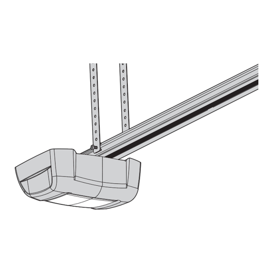
Completed Installation As you proceed with the assembly, installation and adjustment procedures in this manual, you may find it helpful to refer back to this illustration of a com- pleted installation. (1) Cable Pulley Bracket (8) Light Lens (2) Trolley (9) Manual Release Rope &... - Page 6 Assemble Cable Pulley Bracket Insert Carriage Bolt (1) though square hole in Cable Pulley Bracket (4). Remove Chain/Cable assembly (3) from carton. Wrap Cable around Cable Pulley (2) and insert Pulley into Bracket ( NOTE: Make sure the Bracket is assembled in position shown).
-
Page 7: Installation Section
Attach Rail to Unit Turn Rail assembly over. Wrap Chain around Drive Sprocket (1). Slide Rail assembly (2) toward unit and into slots on top of unit. Attach C-Bracket (3) on the rail and secure with screws (4) as shown Push Cable Pulley Bracket forward making Chain tight on sprocket. - Page 8 Install the Header Bracket NOTE: Refer to vertical center and horizontal lines created in step 12 for proper placement of header bracket. A. Wall Mount: Center the header bracket (1) on the vertical center line (2) with the bottom edge of the header bracket on the horizontal line (4) 50mm (with the arrow pointing toward the ceiling).
-
Page 9: Fasten Door Bracket
Fasten Door Bracket A. Place Door Bracket (2) on the top of the door (3) and center over Vertical Center Line (1). Mark the two rear top holes. Drill 4mm holes. B. Mark the two top front holes. Drill 4mm holes. Fasten Door Bracket (2) to the top of the door (3) using Screws (4) Hang Opener Bend Hanging Brackets (1) so they are flat against ceiling. -
Page 10: Connect Electric Power
Connect Door Arm to Trolley A. Preferred Installation: Disconnect Trolley by pulling on the red handle and slide towards door. With door closed connect Straight Door Arm (5) to Trolley (4) with Bolt (3), secure with Nut (1). Connect Curved Door Arm (2) to Door Bracket with Bolt (3) Secure with Nut (1). -
Page 11: Test The Safety Reverse System
Test the Safety Reverse System The safety reverse system test is important. Garage Setting the Force door must reverse on contact with a 40mm obstacle laid flat on the floor. Failure to properly adjust opener The Force is programmed to operate most doors, however, may result in serious personal injury from a closing garage door. -
Page 12: Replace Light Bulb
Replace Light Bulb RED WHT Replace light bulb (1) with a 21 watt ma-mum light bulb. Insert bulb into socket (2) as shown. The light will turn on and remain lit for 2 1/2 minutes when power is connected. After 2 1/2 minutes it will turn off. -
Page 13: Operation Of Your Opener
41A5643 41A5644 41A5674-2 41A5674 012B0905 012B0906 012C0908 012C0788 41A5675 41A5676 Replacement Parts 41A5644 Trolley with Chain/Cable Assy. 41A5674-2 Head Only 41A5643 Hardware Bag 012B0905 Door Bracket 012B0906 Door bracket 012C0788 Header Bracket 012C0908 Rail end piece 41A5675 Rail Hardware 41A5676 Rail Sections Operation Of Your Opener Your opener can be activated by any of the following devices:... -
Page 14: Care Of Your Opener
TROUBLE SHOOTING Specifications 1. Opener doesn’t operate from remote: • Does the opener have electric power? Plug lamp into outlet. If it Input Voltage ... .230 VAC 50/60 Hz doesn’t light, check the fuse box or the circuit breaker. (Some outlets Max. - Page 15 Limited warranty on motor Chamberlain reserves the right to change the design and Chamberlain will furnish a replacement motor free of charge, if it is specification without prior notification. Some features or found to be defective. Labour costs may apply.
- Page 16 NOTES: 114A3449 ANZ...
Need help?
Do you have a question about the MotorLift ML500 and is the answer not in the manual?
Questions and answers