Powermatic SLR12 Operating Instructions And Parts Manual
Straight line rip saw
Hide thumbs
Also See for SLR12:
- Brochure & specs (4 pages) ,
- Operating instructions and parts manual (36 pages)
Table of Contents
Troubleshooting

Subscribe to Our Youtube Channel
Related Manuals for Powermatic SLR12


Summary of Contents for Powermatic SLR12
- Page 1 Operating Instructions and Parts Manual Straight Line Rip Saw Model SLR12 WMH TOOL GROUP 2420 Vantage Drive Elgin, Illinois 60123 Part No. M-0460276 Ph.: 800-274-6848 Revision E 12/05 www.wmhtoolgroup.com Copyright © WMH Tool Group...
-
Page 2: Warranty And Service
This manual has been prepared for the owner and operators of a Powermatic SLR12 Rip Saw. Its purpose, aside from machine operation, is to promote safety using accepted operating and maintenance procedures. To obtain maximum life and efficiency from your rip saw and to aid in using it safely, please read this manual thoroughly and follow the instructions carefully. -
Page 3: Table Of Contents
Parts List: Laser Assembly (Optional Accessory) ................25 Parts List: Table and Stand Assembly ....................26 Table and Stand Assembly.........................28 Parts List: Electrical Control Panel (SLR12-443) .................29 Electrical Connections – 3 Phase, 230V, 60Hz..................30 Electrical Connections – 3 Phase, 460V, 60Hz..................31 Preventive Maintenance.........................32... -
Page 4: Warning
Warning 1. Read and understand the entire owners manual before attempting assembly or operation. 2. Read and understand the warnings posted on the machine and in this manual. Failure to comply with all of these warnings may cause serious injury. 3. -
Page 5: Save These Instructions
blahblahblah 19. Keep the floor around the machine clean and free of scrap material, oil and grease. 20. Keep visitors a safe distance from the work area. Keep children away. 21. Make your workshop child proof with padlocks, master switches or by removing starter keys. 22. -
Page 6: Introduction
This manual is provided by WMH Tool Group covering the safe operation and maintenance procedures for a Powermatic Model SLR12 Rip Saw. This manual contains instructions on installation, safety precautions, general operating procedures, maintenance instructions and parts breakdown. This machine has been designed and constructed to provide years of trouble free operation if used in accordance with instructions set forth in this manual. -
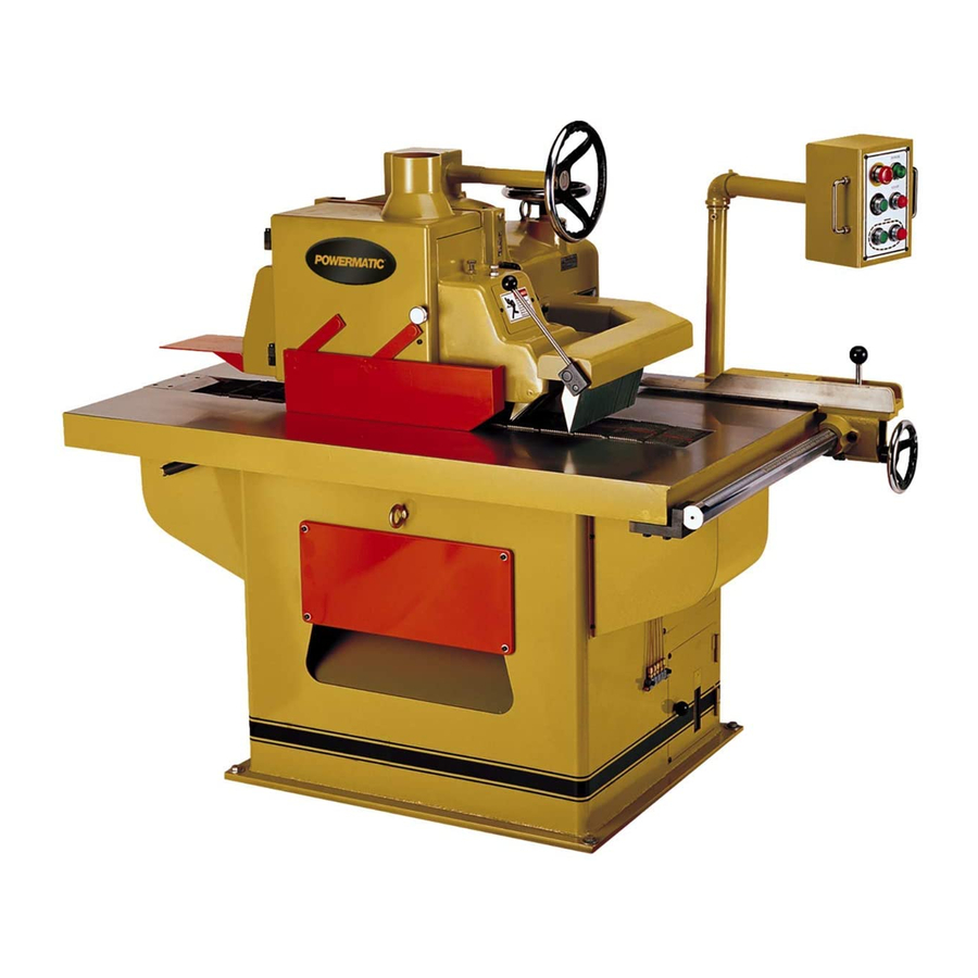
Page 7: Features
Features Figure 1... -
Page 8: Receiving
Receiving Open shipping container and check for shipping damage. Report any damage immediately to your distributor and shipping agent. Do not discard any shipping material until the Rip Saw is installed and running properly. Compare the contents of your container with the following parts list to make sure all parts are intact. -
Page 9: Control Box
The machine must be properly grounded to help prevent electrical shock and possible death. A power plug is not provided with the SLR12. You may either connect one, or "hard-wire" the saw directly to your electrical panel provided there is a disconnect near the machine for the operator. -
Page 10: Installing/Changing Blade
Installing/Changing Blade 1. Disconnect machine from power source. 2. Unscrew knurled knob on blade guard and swing guard away, as shown in Figure 8. 3. Loosen the arbor lock lever (A, Figure 7) and raise the arbor with the handwheel (B, Figure 7) until the blade can slip on to the arbor without... -
Page 11: Adjustments
Adjustments Main Belt Tension 1. Disconnect machine from power source. 2. Open back panels to expose the motor, pulleys and belts, as shown in Figure 10. Loosen hex nut (Fig. 11) and turn the adjustment screw as needed to adjust the tension. -
Page 12: Feed Speed
Feed Speed The feed speed adjuster is found below the gearbox (Figure 13). Feed speed should be adjusted while the machine is running and the caterpillar is in motion. Turn adjuster clockwise to decrease feed speed, counterclockwise to increase. Figure 13 Fence Alignment For accurate cutting, the fence must be parallel to the line of cut:... -
Page 13: Operation
Operation 1. Check the oil tank at the infeed side of the machine (Figure 17). If it is not full, remove the cap and add light 20-weight oil through the fill hole. Replace cap when finished. IMPORTANT: The lubricator has a safety device to ensure a longer service life. -
Page 14: Troubleshooting (Mechanical)
Refill the oil in the gear reducer until the level Oil should be checked weekly, and more added reaches over half its full capacity. if necessary. Use light 20-weight oil. Change the oil after 2000 hours of operation. Insufficient oil Properly clean chips and sawdust from your may cause fast wear of gears;... -
Page 15: Troubleshooting (Electrical)
6080161 Rip Blade, 12” x 36T x 1” 6080159 Rip Blade, 12” x 40T x 1” SLR12-700 Laser Assembly Replacement Parts Replacement parts are listed on the following pages. To order parts or reach our service department, call 1-800-274-6848 between 7:30 a.m. and 6:00 p.m. (CST), Monday through Friday. Having the Model Number and Serial Number of your machine available when you call will allow us to serve you quickly and accurately. -
Page 16: Parts List: Roller And Frame Assembly
Parts List: Roller and Frame Assembly Index No. Part No. Description Size ....SLR12-300....Cover Assembly (Items 1 thru 7) ............1 1....SLR12-301....Cover w/ Dust Port................1 2....SLR12-302....Rotation Shaft..................2 3....SLR12-303....Special Screw..................5 4....TS-1540071 .... Hex Nut, ............M10 ......7 5....SLR12-304.... - Page 17 70 .....SLR12-343....Cover....................1 71 .....SLR12-344....Limit Switch ..................1 72 .....SLR12-345....Bracket ....................1 73 .....SLR12-373....Lock Handle Label (Press Roller)............1 74 .....SLR12-135....Rivet..............#3x5 ......2 75 .....3312341....Powermatic Logo .................. 1...
-
Page 18: Roller And Frame Assembly
Roller and Frame Assembly... -
Page 19: Parts List: Infeed Body Assembly
Description Size ....SLR12-300....Cover Assembly (Items 1 thru 7) ............1 ....SLR12-100....Gear Box Assembly (Items 1 thru 10, 33, 36 and 43)......1 1....TS-1502041 .... Socket Head Cap Screw........M5x16 ......4 2....SLR12-101....Gear Box Cover..................1 3....SLR12-102.... -
Page 20: Infeed Body Assembly
Infeed Body Assembly... -
Page 21: Parts List: Arbor Spindle Assembly
Parts List: Arbor Spindle Assembly Index No. Part No. Description Size ....SLR12-200....Arbor Spindle Assembly (Items 1 thru 13) ..........1 1....TS-1492041 .... Hex Cap Screw..........M12x40 ...... 1 2....TS-2361121 .... Lock Washer............M12 ......14 3....SLR12-201....Arbor Washer ..................1 4....SLR12-202.... -
Page 22: Arbor Spindle Assembly
Arbor Spindle Assembly... -
Page 23: Parts List: Motor And Drive Unit Assembly
39 .....SLR12-523....Idle Wheel .................... 2 41 .....SLR12-524....Sprocket ............10T......1 42 .....SLR12-525....Key..............10 x 8 x 60....1 44 .....TS-2311101 .... Hex Nut ............. M10 ......2 45 .....TS-1491041 .... Hex Cap Screw..........M10x30 ...... 2 47 .....TS-0803052 .... -
Page 24: Motor And Drive Unit Assembly
Motor and Drive Unit Assembly... -
Page 25: Parts List: Laser Assembly (Optional Accessory)
8....TS-1550021 .... Flat Washer ............M4 ......2 9....SLR12-705....Mounting Bracket.................. 1 10 .....SLR12-706....Cord Holder ..................6 11 .....SLR12-707....DC Power Connector (Male) ..............1 ....SLR12-714....Transformer Assembly (Items 12 thru 18)..........2 12 .....SLR12-708....DC Power Connector (Female) ............. 1 13 .....SLR12-709.... -
Page 26: Parts List: Table And Stand Assembly
Index No. Part No. Description Size ....SLR12-400....Fence Assembly (Items 15 ,20 thru 31, 52 thru 58) ........ 1 1....SLR12-401....Bracket ....................1 2....TS-1506051 .... Socket Head Cap Screw........M12x40 ...... 4 3....TS-2361121 .... Lock Washer............M12 ......4 4....TS-2360121 .... - Page 27 63 .....SLR12-438....Start Button ..................2 65 .....SLR12-440....Stop Button................... 2 67 .....SLR12-442....Start Button, Power On ................. 1 68 .....SLR12-443....Electrical Control Assembly..............1 69 .....SLR12-444....Handle....................2 70 .....SLR12-445....Bracket ....................1 71 .....SLR12-446....
-
Page 28: Table And Stand Assembly
Table and Stand Assembly... -
Page 29: Parts List: Electrical Control Panel (Slr12-443)
9....SLR12-609....Overload ......OL2......LR3D126, 23~32A ..1 10 .....SLR12-610....Switch......M1 ......LC1D256 ....1 11 .....SLR12-611....Overload ......OL1......LR3D326 5.5~8A ..1 12 .....SLR12-612....Switch......D1......LC1D256 ....1 13 .....SLR12-613....Switch ......S1......LC1D186 ....1 14 .....SLR12-614.... -
Page 30: Electrical Connections - 3 Phase, 230V, 60Hz
Electrical Connections – 3 Phase, 230V, 60Hz... -
Page 31: Electrical Connections - 3 Phase, 460V, 60Hz
Electrical Connections – 3 Phase, 460V, 60Hz... -
Page 32: Preventive Maintenance
Preventive Maintenance Checklist for Model SLR12 Straight Line Rip Saw Work area around machine marked off clearly. Non-skid floor strips in area where operator normally stands. Inspect entire machine for loose bolts, nuts, screws. Tighten and replace as necessary. Clean table area, removing sawdust and chips with a soft bristle brush. Remove gum and pitch with oven cleaner.
Need help?
Do you have a question about the SLR12 and is the answer not in the manual?
Questions and answers