
Related Manuals for Powermatic PWBS14


Summary of Contents for Powermatic PWBS14
- Page 1 Operating Instructions and Parts Manual 14” Woodworking Band Saw Model PWBS14 WMH TOOL GROUP 2420 Vantage Drive Elgin, Illinois 60123 Part No. M-1791216 Ph.: 800-274-6848 Rev D 1/04 www.wmhtoolgroup.com Copyright © WMH Tool Group...
- Page 2 Authorized Repair Stations located throughout the United States can give you quick service. In most cases, any one of these WMH Tool Group Repair Stations can authorize warranty repair, assist you in obtaining parts, or perform routine maintenance and major repair on your JET, Performax, Powermatic or Wilton tools.
-
Page 3: Table Of Contents
TABLE OF CONTENTS Safety Rules............................ 4-5 Safety Decal............................6 Grounding Instructions........................7-8 Specifications............................. 9 Dimensions ............................10 Receiving ............................11 Installation & Assembly ........................11 Mounting Rails & Rip Fence ......................16 Tilting the Table ..........................19 Adjusting 90 Table Stop ........................19 Changing Blades ..........................20 Adjusting Blade Tension ........................21 Adjusting Blade Tracking........................21 Adjusting Upper Blade Guide Assembly ....................22... -
Page 4: Safety Rules
SAFETY RULES As with all machines, there is a certain amount of hazard involved with the use of this band saw. Use the machine with the respect and caution demanded where safety precautions are concerned. When normal safety precautions are overlooked or ignored, personal injury to the operator can result. •... - Page 5 • MAINTAIN TOOLS WITH CARE. Keep tools sharp and clean for best and safest performance. Follow instructions for lubricating and changing accessories. • DISCONNECT TOOLS before servicing; when changing accessories, such as blades, bits cutters, and the like. • REDUCE THE RISK OF UNINTENTIONAL STARTING. Make sure the switch is in the off position before plugging in the machine.
-
Page 6: Safety Decal
SAFETY Familiarize yourself with the location and content of this decal on your machine. Fig. 1... -
Page 7: Grounding Instructions
Grounding Instructions Caution: This tool must be grounded while in use to protect the operator from electric shock. In the event of a malfunction or breakdown, grounding provides a path of least resistance for electric current to reduce the risk of electric shock. This tool is equipped with an electric cord having an equipment- grounding conductor and a grounding plug. - Page 8 230 Volt Operation If 230V, single-phase operation is desired, the following instructions must be followed: 1. Disconnect the machine from the power source. 2. This band saw is supplied with four motor leads that are connected for 115V operation, as shown in Figure A.
-
Page 9: Specifications
Body ..........................178 lbs Closed Stand ........................87.5 lbs NOTE: The above specifications were current at the time this manual was published, but because of our policy of continuous improvement, Powermatic reserves the right to change specifications without notice and without incurring obligations. -
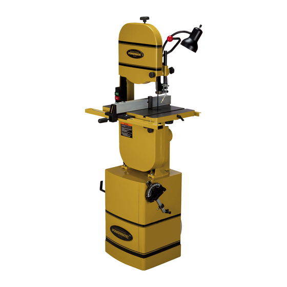
Page 10: Dimensions
PWBS-14 Band Saw Dimensions Fig. 1A... -
Page 11: Receiving
RECEIVING Open shipping container and check for shipping damage. Report any damage immediately to your distributor and shipping agent. Read the instruction manual thoroughly for assembly, maintenance and safety instructions. Contents: Container #1 1 saw body 1 v-belt 1 trunnion support 1 main table 1 extension table 2 table lock knobs... - Page 12 With the aid of a second person, lift the saw body out of the shipping container and place on top of the stand. Be sure front of saw (with Powermatic logo) faces curved stand front. WARNING Saw body is heavy! Use caution when lifting...
- Page 13 Loosen the nuts on the four motor mounting bolts (Fig. 4), and tension the v-belt by pushing down on the motor. Tighten the four motor mounting nuts. The v-belt is properly tensioned when finger pressure between the two pulleys causes approximately 1/2"...
- Page 14 13. To mount the main table, remove pin and insert from the table (Fig. 8). 14. Rotate the table so that the saw blade will slide through the slot in the table. Then orient the table so the screws will slide into the holes on the trunnion support.
- Page 15 20. The air hose, which is already connected to the saw body, should be inserted through the hole in the stand and connected to the nozzle of the air regulator (Fig. 10). Use a lighter or match to briefly heat the end of the hose so that it will slip over the nozzle.
-
Page 16: Mounting Rails & Rip Fence
23. Install blade tension lever (Fig. 11a) and tighten the set screws, using a 3mm hex wrench. The movement of the blade tension lever is explained under “Changing Blades”. 24. Mount the two miter gauge hooks (A, Fig. 12) to the side of the stand with two M8 x 16 carriage bolts and two flanged hex nuts. - Page 17 Mount front rail (A, Fig. 14) to the band saw table using two M6 x 20 hex cap screws, two 1/4" lock washers and two 1/4" flat washers (B, Fig. 14). Do not tighten yet. Mount guide rail (A, Fig. 15) to the front rail using three M6 x 20 hex cap screws, three 1/4"...
- Page 18 Thread a hex nut (A, Fig. 17) onto the sliding pad (B, Fig. 17) and insert through the fence and rear hook (C, Fig. 17). Secure in place using a hex nut, lock washer and flat washer (D, Fig. 17). The hook (C, Fig. 17) should be adjusted so that it overlaps the rear rail by approximately 1/8".
-
Page 19: Tilting The Table
14. For resawing operations attach the resaw guide (Fig. 20) to the fence with the knob. There is a slotted hole in the fence that will accomodate the resaw kit. Position the resaw guide so that it is centered with the front edge of the saw blade. -
Page 20: Changing Blades
Loosen jam nut (C, Fig. 23) and turn table stop (B, Fig. 23) left or right to raise or lower the stop. Tighten jam nut to hold table stop in place. Unlock the table and tilt it back on to the table stop to confirm table is 90 degrees to the blade. -
Page 21: Adjusting Blade Tension
Adjusting Blade Tension Disconnect machine from power source. Place tension lever in the highest position, as shown in Figure 25. Turn blade tension knob (B, Fig. 25) clockwise to tension blade. A gauge on the upper wheel slide bracket (C, Fig. -
Page 22: Adjusting Upper Blade Guide Assembly
Tighten wing nut (D, Fig. 25) after blade is tracking in the center of the wheel. Close upper wheel guard. Adjusting Upper Blade Guide Assembly Disconnect machine from power source. Loosen lock knob (A, Fig. 26) and raise or lower upper blade guide assembly (B, Fig. 26) to just above the material being cut. -
Page 23: Adjusting Lower Blade Guide & Blade Support Bearing
Adjusting Lower Blade Guide and Blade Support Bearing Disconnect machine from power source. Blade must already be tensioned and tracking properly. Loosen thumb screw (A, Fig. 29) and move guide block by turning knob (B, Fig. 29) so that the front of the guide wheels (C, Fig. 29) are just behind the gullet (curved area at base of tooth) of the blade. -
Page 24: Trouble-Shooting
TROUBLE-SHOOTING (PWBS-14 Band Saw) PROBLEM POSSIBLE CAUSE SOLUTION Saw stops or will not start 1. Saw unplugged 1. Check plug connections 2. Fuse blown or circuit breaker tripped 2. Replace fuse or reset circuit breaker 3. Cord damaged 3. Replace cord Does not make accurate 1. -
Page 25: Optional Accessories
OPTIONAL ACCESSORIES for PWBS-14 Band Saw Part No. Description Size 709370 ... Bandsaw Blade ....1/8 x .020 x 14 hook x 93-1/2" 709371 ... Bandsaw Blade ....3/16 x .020 x 6 skip x 93-1/2" 709372 ... Bandsaw Blade ....1/4 x .020 x 6 skip x 93-1/2" 709373 ... -
Page 26: Replacement Parts & Service
Replacement Parts & Service Replacement parts are listed on the following pages. To order parts or reach our service department, call 1-800-274-6848 between 7:00 a.m. and 6:00 p.m. (CST), Monday through Friday. Having the Model Number and Serial Number of your machine available when you call will allow us to serve you quickly and accurately. - Page 27 26..TS-1540083 ....Hex Nut ..........M12x1.25........ 1 27..........Saw Blade (see “Optional Accessories”) ..........1 28..PWBS14-128....Cover Upper Back ................1 29..PWBS14-129....Pan Head Flanged Screw...... M5x8 ........2 30..PWBS14-130....Tapping Screw ........M4X8 ........12 31..PWBS14-131....Guard Blade Rear ................1 32..
- Page 28 84 ..TS-1522011....Socket Set Screw........M5x6 ........1 85 ..PWBS14-185 ....Star Washer (External) ......M5...........2 86 ..PWBS14-186 ....Phillips Pan Head Machine Screw..M5x6 ........2 87 ..PWBS14-187 ....Strain Relief ..................2 88 ..PWBS14-188 ....Cord Clamp ..................1 89 ..
- Page 29 138..TS-1551031 ....Lock Washer ......... M5 .......... 2 139..PWBS14-239 ....Support Bracket..................2 140..PWBS14-240 ....Eccentric Shaft ..................4 141..PWBS14-241 ....Lower Support Bracket Post ..............1 142..PWBS14-242 ....Thumb Screw ........M6x12........1 143..PWBS14-243 ....Lampshade ..................1 144..PWBS14-244 ....Lamp Holder..................1 145..PWBS14-245 ....Nut ............
-
Page 30: Body Assembly
Body Assembly (PWBS-14 Band Saw) -
Page 31: Miter Gauge Assembly
Index Part Description Size Qty....PWBS14-251 ....Miter Gauge Assembly (Items 1 thru 9) ..........1 1....PWBS14-251-1 ...Guide Bar..................... 1 2....PWBS14-251-2 ...Guide Piece ..................1 3....PWBS14-251-3 ...Counter Sunk Bolt ......... M6x6 ........1 4....PWBS14-251-4 ...Pointer ....................1 5....PWBS14-251-5 ...Pan Head Flanged Screw...... -
Page 32: Table & Trunnion Assembly
45 ..PWBS14-145 ....Trunnion Clamp Shoes .................2 46 ..TS-1491081....Hex Cap Screw........M10x50 ........2 47 ..PWBS14-147 ....Hex Head Flange Bolt ................6 48 ..TS-1490151....Hex Cap Screw........M8x80 ........1 49 ..TS-1540061....Hex Nut ..........M8...........1 50 .. -
Page 33: Table & Trunnion Assembly
Table & Trunnion Assembly (PWBS-14 Band Saw) - Page 34 Index Part Description Size Qty. 93 ..PWBS14-193A ..... Adjusting Block Assembly (Items 93-1 thru 93-13) .........1 93-1 ..PWBS14-193-1 .... Side Cover....................1 93-2 ..PWBS14-193-2 .... Spring Pin .....................1 93-3 ..PWBS14-193-3A ..Gear .....................1 93-5 ..PWBS14-193-5A ..Adjust Block..................1 93-7 ..
-
Page 35: Blade Tension Lever
Blade Tension Lever (PWBS-14 Band Saw) -
Page 36: Closed Stand Assembly
6 ..PWBS14-306 ....Knob ............. M6X12........2 7 ..TS-1540061....Hex Nut ..........M8...........4 8 ..PWBS14-308 ....Air Regulator Assembly (Items 8-1 thru 8-14).........1 8-1 ..PWBS14-308-1 .... Lower Wheel Guard ................1 8-2 ..PWBS14-308-2 .... Upper Wheel Guard ................1 8-3 .. -
Page 37: Closed Stand Assembly
Closed Stand Assembly (PWBS-14 Band Saw) -
Page 38: Fence & Rail Assembly
Index Part Description Size Qty. 1 ..PWBS14-F01 ....Powermatic Label ..................1 2 ..JWBS18-431 ....Knob ......................1 3 ..JWBS18-432 ....Lock Handle...................1 4 ..JWBS18-433 ....Lock Plate....................1 5 ..JWBS18-434 ....Pad ......................5 6 .. -
Page 39: Fence & Rail Assembly
Fence & Rail Assembly (PWBS-14 Band Saw) - Page 40 WMH Tool Group 2420 Vantage Drive Elgin, Illinois 60123 Phone: 800-274-6848 www.wmhtoolgroup.com...
Need help?
Do you have a question about the PWBS14 and is the answer not in the manual?
Questions and answers