Table of Contents
Advertisement
Advertisement
Chapters
Table of Contents

Subscribe to Our Youtube Channel
Related Manuals for Sailor RT2047


Summary of Contents for Sailor RT2047
- Page 1 S.P. RADIO A/S AALBORG DENMARK...
- Page 3 RT2047 DSC - PART I CONTENTS GENERAL INFORMATION INTRODUCTION INSTALLATION INSTALLATION HINTS MOUNTING POSSIBILITIES DIMENSIONS AND DRILLING PLAN HANDSET MICROTELEPHONE CONNECTOR POWER SUPPLY POWER AND EXT. LOUDSPEAKER CONNECTOR 2-10 ANTENNAS 2-10 SPECIAL OPTIONS 2-10 2.10 REAR VIEW OF VHF RT2047 2-11 2.11...
- Page 4 RT2047 DSC - PART II CONTENTS GENERAL INFORMATION GENERAL DESCRIPTION TECHNICAL DATA CONTROLS PRINCIPLE OF OPERATION BLOCKDIAGRAM CIRCUIT DESCRIPTION RECEIVER UNIT MODULE 100 RX-SYNTHESIZER UNIT MODULE 200 TX-EXCITER UNIT MODULE 300 TX-POWER AMPLIFIER MODULE 400 2-13 ANTENNA RELAY (500) 2-13...
- Page 5 RT2047 DSC - PART I CONTENTS GENERAL INFORMATION INTRODUCTION...
-
Page 7: General Information
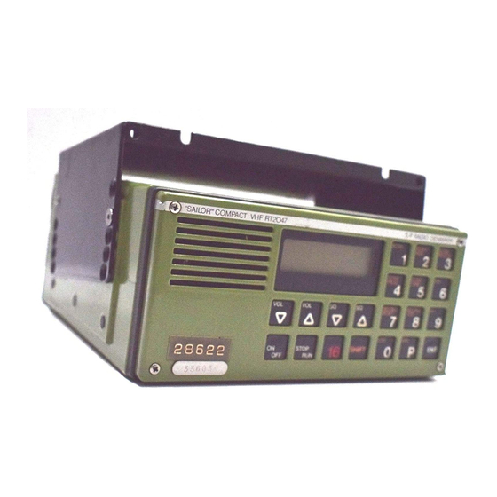
The RT2047 VHF Radiotelephone has been designed to be used with the Compact 2000 Module Programme. The VHF RT2047 can either be installed and operated as an independent unit or in combination with the other modules in the Compact 2000 programme. These modules include a complete range of SSB transmitters and receivers, MF/HF Digital Selective Calling unit and/or radiotelex equipment, a scrambler that ensures complete communication secrecy and a VHF Digital Selective Call (DSC) unit. -
Page 9: Table Of Contents
RT2047 DSC - PART I CONTENTS INSTALLATION INSTALLATION HINTS MOUNTING POSSIBILITIES DIMENSIONS AND DRILLING PLAN HANDSET MICROTELEPHONE CONNECTOR POWER SUPPLY POWER AND EXT. LOUDSPEAKER CONNECTOR 2-10 ANTENNAS 2-10 SPECIAL OPTIONS 2-10 2.10 REAR VIEW OF VHF RT2047 2-11 2.11 STANDARD FREQUENCY TABLE... -
Page 11: Installation
INSTRUCTIONS FOR IDENTITY AND SERVICE PROGRAMMING OF VHF RT2047. This manual will only be delivered to dealers and general agents where it will be at the disposal of trained personal in their service facilities. -
Page 12: Mounting Possibilities
2 INSTALLATION RT2047 DSC - PART I 2.2 MOUNTING POSSIBILITIES TABLETOP AND DECKHEAD 24889 Mounting bracket H2055 24890 Mounting kit H2068 and H2055 PAGE 2-2... - Page 13 2 INSTALLATION RT2047 DSC - PART I BULKHEAD AND CONSOLE 24892 Mounting kit H2063 24893 Mounting kit H2062 24891 Mounting kit H2064 IN CONJUNCTION WITH OTHER “S.P. RADIO” EQUIPMENT. Look up the INSTALLATION section for the S.P. RADIO unit in question.
-
Page 14: Dimensions And Drilling Plan
2 INSTALLATION RT2047 DSC - PART I 2.3 DIMENSIONS AND DRILLING PLAN UNIVERSAL MOUNTING BRACKET H2055 Permits a wide variety of installation possibilities, such as table top, bulkhead or deck head installation. Fur other possibilities such as console installation, installation with 19" rack or assembly of all units in the Compact programme on the bulkhead, see special information concerning installation of the Compact programme. - Page 15 2 INSTALLATION RT2047 DSC - PART I 4 pcs M5x8 24896 Mounting kit H2068 and H2055 24895 α WEIGHT Mounting kit H2068 and H2055 : 1.5 kg 0° H2054 : 5.5 kg 4.8° H2074 : 4.0 kg 9.6° CRY2001 : 3.2 kg 14.4°...
- Page 16 2 INSTALLATION RT2047 DSC - PART I Mounting kit H2063 min.295 24898 Free distance must be kept to 253mm allow free air circulation ambient 240mm temperature max. 40°C. 4.5mm 4.5mm 4 stk 6mm WEIGHT 4 stk 3.5mm uns for M3 DIN 963 Mounting kit H2063 : 1.0 kg...
- Page 17 2 INSTALLATION RT2047 DSC - PART I Mounting kit H2064 min.295 24772 Free distance must be kept to 253.00 allow free air circulation ambient 240.00 temperature max. 40°C. 4.5mm 4.5mm 4 stk ø6mm WEIGHT 4 stk ø3.5mm uns for M3 DIN 963 Mounting kit H2064 : 1.5 kg...
- Page 18 2 INSTALLATION RT2047 DSC - PART I Mounting kit H2062 min 295 28369 Free distance must be kept to allow free air circulation ambient 473mm 460mm temperature max. 40°C. 225.5mm 225.5mm 4.5mm 2 stk ø3mm 4 stk ø6mm 8 stk ø3.5mm uns for M3 DIN 963...
-
Page 19: Handset
Signal selection on jumper P934 on the Filter-unit 2.6 POWER SUPPLY The standard power supply for RT2047 is 12V DC . For 24V DC supply an external power supply N418 ( switch mode ) or the N420 a 24V DC to 13.2V DC serial regulator can be used, see part II, section 2.14 . -
Page 20: Antennas
Jumper P34-9 is used for selecting if The ‘Phone Patch’ signal or if ‘+13V’ should be led to the handset key connector. +13V is required when RT2047 is used with the VHF DSC RM2042 and Phone Patch is used for the Phone Patch unit H2047. -
Page 21: Rear View Of Vhf Rt2047
2 INSTALLATION RT2047 DSC - PART I 2.10 REAR VIEW OF VHF RT2047 Screws for Tx Power Transistor Power Supply Cable groove for T401’s heat sink conductor. connector P802 special options 12V DC 28368 Screws for Regulator Transistors Microtelephone Antenna heat sink on Interface unit(6). -
Page 22: Standard Frequency Table
2 INSTALLATION RT2047 DSC - PART I 2.11 STANDARD FREQUENCY TABLE &+$11(/ 75$160,77,1* 5(&(,9,1* )5(48(1&< 0+] )5(48(1&< 0+] INT’L MODE US MODE (INT-CHANNELS) (A-CHANNELS) 156.050 160.650 156.050 156.100 160.700 160.700 156.150 160.750 160.750 156.200 160.800 160.800 156.250 160.850 156.250 156.300 156.300... -
Page 23: General Information
RT2047 DSC - PART II CONTENTS GENERAL INFORMATION GENERAL DESCRIPTION TECHNICAL DATA CONTROLS PRINCIPLE OF OPERATION 1.4.1 FREQUENCY GENERATION 1.4.2 RECEIVER 1.4.3 TRANSMITTER 1.4.4 THE MICROCOMPUTERS BLOCKDIAGRAM 9546... -
Page 25: General Information
EEPROMS, controlling the squelch and volume functions, and controlling the selcall filter. The other µC is controlling the display drivers, the dual watch and scanning functions. RT2047 is for 12 Volt DC supply. Voltage change-over from 24V to 12V is done by the switch-mode power supply N418. -
Page 26: Technical Data
1 GENERAL INFORMATION RT2047 DSC - PART II 1.2 TECHNICAL DATA VHF RT2047 fulfils the International CAPT regulations. GENERAL SPECIFICATIONS All international maritime VHF channels Private Channels 20 as option up to 67 Operation Duplex and Simplex Modulation G3EJN (Phase) -
Page 27: Controls
1 GENERAL INFORMATION RT2047 DSC - PART II 1.3 CONTROLS SCAN SCAN SCAN DELETE Scan DW USA CQ Duplex Shift Call SCAN SCAN D.W. PROG TIME SELCALL SELCALL RESET TEST STOP SHIFT 23990 Press Turns the set on or off. - Page 28 Tests the selcall decoder. Press Selects 1 W reduced power output. Press Selects the VHF channels used in USA. Press Switches the panel illumination on or off. Note: See the VHF RT2047 Operating Manual for functional description. PAGE 1-4 9543...
-
Page 29: Principle Of Operation
1 GENERAL INFORMATION RT2047 DSC - PART II 1.4 PRINCIPLE OF OPERATION 1.4.1 FREQUENCY GENERATION The frequencies are generated from a crystal oscillator operating on 21 MHz. The 21 MHz is divided in the REFERENCE DIVIDER to 2.1 MHz which is the input to the RX-REFERENCE DIVIDER and also the clock-signal for the microcomputer on the Interface Unit. - Page 30 1 GENERAL INFORMATION RT2047 DSC - PART II PAGE 1-6 9543...
-
Page 31: Blockdiagram
1 GENERAL INFORMATION RT2047 DSC - PART II 1.5 BLOCKDIAGRAM INTERFACE (MODULE 6) 2.1MHz Programm- Duplex Rx-Filter able ÷2 Filter Control-AMP Counter +13V +13V +13V PS Switched RECEIVER (MODULE 100) Capacitor -13V PS Filter ON/OFF AMP/Limiter Detector Bandpass Control LCD-... - Page 33 RT2047 DSC - PART II CONTENTS CIRCUIT DESCRIPTION RECEIVER UNIT MODULE 100 RX-SYNTHESIZER UNIT MODULE 200 TX-EXCITER UNIT MODULE 300 TX-POWER AMPLIFIER MODULE 400 2-13 ANTENNA RELAY (500) 2-13 INTERFACE UNIT MODULE 6/600 2-17 KEYBOARD UNIT MODULE 7/700 2-24 DUPLEX FILTER MODULE 800...
-
Page 35: Circuit Description
2 CIRCUIT DESCRIPTION RT2047 DSC - PART II CIRCUIT DESCRIPTION 2.1 RECEIVER UNIT MODULE 100 The receiver unit includes the following circuits: 2.1.1 RF-AMPLIFIER AND FIRST MIXER The RF-amplifier working in the frequency range 155.4 MHz to 162.4 MHz consists of the transistor Q101 and the two double-tuned filters surrounding it. - Page 36 2 CIRCUIT DESCRIPTION RT2047 DSC - PART II COMPONENT LOCATION RECEIVER UNIT MODULE 100 View from component side View from component side with upper side tracks. with lower side tracks. 32127B PAGE 2-2 9641...
- Page 37 2 CIRCUIT DESCRIPTION RT2047 DSC - PART II DIAGRAM RECEIVER UNIT MODULE 100 AC voltages outside frame of diagram. : Measured with oscilloscope or frq. counter. : Measured with test probe. : Connections to module. : Approx. measurement with test probe.
-
Page 38: Rx-Synthesizer Unit Module
2 CIRCUIT DESCRIPTION RT2047 DSC - PART II 2.2 RX-SYNTHESIZER UNIT MODULE 200 The RX-synthesizer unit includes the following circuits: 2.2.1 RX-VCO AND BUFFER AMPLIFIERS The transistor T203 is producing 8.3 V supply voltage for the RX-VCO and bias for the buffer amplifiers consisting of the transistors T201 and T204. - Page 39 2 CIRCUIT DESCRIPTION RT2047 DSC - PART II 2.2.4 PHASE DETECTOR PUMP AND LOOP FILTER We assume that the RX-VCO frequency has decreased from its nominal frequency, The phase-detector now sends negative correction pulses from IC202 pin 17 to T210, which goes on. A current will then flow from C225 through R225 and R229 and into T210.
- Page 40 2 CIRCUIT DESCRIPTION RT2047 DSC - PART II COMPONENT LOCATION RX-SYNTHESIZER UNIT MODULE 200 View from component side View from component side with upper side tracks. with lower side tracks. 23694D PAGE 2-6 9543...
- Page 41 2 CIRCUIT DESCRIPTION RT2047 DSC - PART II DIAGRAM RX-SYNTHEZISER UNIT MODULE 200 AC voltages outside frame of diagram. : Measured with oscilloscope or frq. counter. : Measured with test probe. : Connections to module. : Approx. measurement with test probe.
-
Page 42: Tx-Exciter Unit Module
2 CIRCUIT DESCRIPTION RT2047 DSC - PART II 2.3 TX-EXCITER UNIT MODULE 300 The TX exciter unit contains the following circuits: 2.3.1 INSULATION BUFFER AND 16.8 MHZ MIXER From RX-VC0 the signal is led to transistor T301 and from TX-VC0 the signal is led to transistor T302. - Page 43 2 CIRCUIT DESCRIPTION RT2047 DSC - PART II 2.3.4 TX-VCO The TX-VCO comprises a Field Effect Transistor T311 (oscillator transistor), two coaxial coils L309 and L310, the capacitors C343 and C345, and a variocapacitor diode D302. The frequency is mainly determined by L309, L310, C345, and D302. The TX-VCO is a Voltage Controlled Oscillator, where the control voltage from the loop filter determines the frequency by means of the variocapacitor diode D302.
- Page 44 2 CIRCUIT DESCRIPTION RT2047 DSC - PART II COMPONENT LOCATION TX-EXCITER UNIT MODULE 300 View from component side with upper side tracks. View from component side with lower side tracks. 23695D 9543 PAGE 2-10...
- Page 45 2 CIRCUIT DESCRIPTION RT2047 DSC - PART II DIAGRAM TX-EXCITER UNIT MODULE 300 AC voltages outside frame of diagram. : Measured with oscilloscope or frq. counter. : Measured with test probe. : Connections to module. : Approx. measurement with test probe.
- Page 46 2 CIRCUIT DESCRIPTION RT2047 DSC - PART II PAGE 2-12 9543...
-
Page 47: Tx-Power Amplifier Module
2 CIRCUIT DESCRIPTION RT2047 DSC - PART II 2.4 TX-POWER AMPLIFIER MODULE 400 The TX-power-amplifier includes the amplifier and a harmonic filter. 2.4.1 TX-POWER-AMPLIFIER The amplifier consists of a single transistor output amplifier and a two transistor power driver. The transistors are both tuned classic amplifier circuits. - Page 48 2 CIRCUIT DESCRIPTION RT2047 DSC - PART II COMPONENT LOCATION TX-POWER AMPLIFIER MODULE 400 AND ANTENNA RELAY (500) View from component side with upper side tracks. View from component side with lower side tracks. PAGE 2-14 9619...
- Page 49 2 CIRCUIT DESCRIPTION RT2047 DSC - PART II DIAGRAM TX-POWER AMPLIFIER MODULE 400 AND ANTENNA RELAY (500) AC voltages outside frame of diagram. : Measured with AF voltmeter. Test conditions. Voltages without brackets: Operating in Rx position. With antenna signal 1 mV EMF: f= +3 KHz;...
- Page 50 2 CIRCUIT DESCRIPTION RT2047 DSC - PART II PAGE 2-16 9543...
-
Page 51: Interface Unit Module
2 CIRCUIT DESCRIPTION RT2047 DSC - PART II 2.6 INTERFACE UNIT MODULE 6/600 2.6.1 ON/OFF FUNCTION When the ON/OFF push button is activated Q4-6 is turned on and the relay RE3-6 is engaged. When the µC leaves reset condition PC5 is set to high level and Q5-6 will be conducting, keeping Q4-6 on. - Page 52 2 CIRCUIT DESCRIPTION RT2047 DSC - PART II 2.6.7 PA REGULATOR By means of the PA regulator it is possible to adjust the output power of the transmitter. When the output from U3/2-6 is changed from O to 5V, Q7-6 is turned off. Thus Q8-6 is turned on and then also Q2-6 and Q1-6 and the output voltage rises.
- Page 53 2 CIRCUIT DESCRIPTION RT2047 DSC - PART II 2.6.11 AF CIRCUITS The AF signal from the receiver is fed to the active filter U5/2-6. The filter provides a frequency response of -6 dB/Oct. in the range 0.3 to 3 KHz and limits the signals outside this range. Further the signal is fed to the telephone output amplifier U6/2-6 and Q6-6.
- Page 54 2 CIRCUIT DESCRIPTION RT2047 DSC - PART II When the radio is switched on the dividing figure corresponding to the first figure in the selcall number is put on port A on the µC which is connected to the input of U18-6. If the correct tone is received the output of the comparator U15/1-6 goes low.
- Page 55 When the transmitter is keyed the input PD2 on the Interface µC is put to a high level by the Keyboard µC assuming that TX is allowed, TX can be prohibited when the RT2047 is operated as a slave over the SP VHF Bus ( Described in section 2.7.5 The SP VHF Bus ).
- Page 56 2 CIRCUIT DESCRIPTION RT2047 DSC - PART II COMPONENT LOCATION INTERFACE UNIT MODULE 6/600 View from component side with upper side tracks. View from component side with lower side tracks. 27746D PAGE 2-22 9543...
- Page 57 2 CIRCUIT DESCRIPTION RT2047 DSC - PART II DIAGRAM INTERFACE UNIT MODULE 6/600 This diagram is valid for PCB rev. 27746D. 9543 PAGE 2-23...
-
Page 58: Keyboard Unit Module
23 (PC5) on the µC and the serial I/O signals on pin 29/30 (PD0/PD1). The RT2047 will always behave as a slave in the communication but can initiate a dialogue with the external unit by setting the interrupt pin. A communication sequence will typically be initiated by the... -
Page 59: Dual Watch
2 CIRCUIT DESCRIPTION RT2047 DSC - PART II Q5-7, R18-7 and R19-7 is the Interrupt driver circuit and U10/2-7, Q4-7, C17-7, R14-7 - 16-7 and R22/ 1-7 - R22/4-7 forms the serial interface circuit. This circuit transforms the µC’s two-wire serial communication interface (SCI) into the one-wire SCI required for communication with external units. - Page 60 2 CIRCUIT DESCRIPTION RT2047 DSC - PART II COMPONENT LOCATION KEYBOARD UNIT MODULE 7/700 View from component side with upper side tracks. View from component side with lower side tracks. 27747C PAGE 2-26 9543...
- Page 61 2 CIRCUIT DESCRIPTION RT2047 DSC - PART II DIAGRAM KEYBOARD UNIT MODULE 7/700 This diagram is valid for PCB rev. 27747C. 9543 PAGE 2-27...
-
Page 62: Duplex Filter Module
See the plot of duplex filters frequency response below. NB: The duplex filter is adjusted with special measuring equipment and should be adjusted by S.P. Radio A/S only. TECHNICAL DATA FOR DUPLEX FILTER FOR VHF RT146 - RT2047. 75$160,77(5 5$1*( 0+] Band-stop attenuation 151.425 - 152.825... -
Page 63: Filter Unit Module
2 CIRCUIT DESCRIPTION RT2047 DSC - PART II 2.9 FILTER UNIT MODULE 9/900 The function of the Filter unit is to protect the set against RF interference from equipment installed near the set. The two options AUX II and SELCALL RELAY requires the relays RE1-9 and RE2-9. These relays are not a standard feature and can, if needed, be acquired from SP-Radio ( order number 21.300 ). - Page 64 2 CIRCUIT DESCRIPTION RT2047 DSC - PART II COMPONENT LOCATION FILTER UNIT MODULE 9/900 View from component side with upper side tracks. View from component side with lower side tracks. 27749C 9543 PAGE 2-30...
- Page 65 2 CIRCUIT DESCRIPTION RT2047 DSC - PART II DIAGRAM FILTER UNIT MODULE 9/900 This diagram is valid for PCB rev. 27749C. 9543 PAGE 2-31...
- Page 66 9546...
- Page 67 2 CIRCUIT DESCRIPTION RT2047 DSC - PART II 32162 9546 PAGE 2-33...
-
Page 68: Microtelephone Installation
2 CIRCUIT DESCRIPTION RT2047 DSC - PART II 2.11 MICROTELEPHONE INSTALLATION VHF RT2047 SCRAMBLER CRY2001, RE2100, RT2047 prepared for DSC and RT2048 SHORTWAVE S130X YELLOW YELLOW WHITE BROWN BROWN BROWN TC801 TC1701 HAND KEY HAND KEY HAND KEY S801 S1701... -
Page 69: Special Installation With 2 Microtelephones
2 CIRCUIT DESCRIPTION RT2047 DSC - PART II 2.12 SPECIAL INSTALLATION WITH 2 MICROTELEPHONES H2086 for scrambler CRY2001, RT2047 DSC, RT2048 and RE2100. H2087 for VHF RT2047. NORMAL MICROTELEPHONE H2087 H2086 Hook 1 program 2000 (HANDSET) MICROTELEPHONE MICROTELEPHONE CONNECTOR CONNECTOR... -
Page 70: Special Installation With 3 Microtelephones
2 CIRCUIT DESCRIPTION RT2047 DSC - PART II 2.13 SPECIAL INSTALLATION WITH 3 MICROTELEPHONES H2088 for scrambler CRY2001, RT2047 DSC, RT2048 and RE2100. H2089 for VHF RT2047. NORMAL MICROTELEPHONE H2089 H2088 Hook 1 program 2000 (HANDSET) MICROTELEPHONE MICROTELEPHONE CONNECTOR CONNECTOR... -
Page 71: Mechanical Dimensions For Handset
2 CIRCUIT DESCRIPTION RT2047 DSC - PART II 2.14 MECHANICAL DIMENSIONS FOR HANDSET MECHANICAL DIMENSIONS FOR HANDSET ø4.5 ø4.5 27946 MECHANICAL DIMENSIONS FOR HANDSET HOLDER WITH MICROSWITCH ø4.5 ø4.5 26999 9543 PAGE 2-37... - Page 72 2 CIRCUIT DESCRIPTION RT2047 DSC - PART II MECHANICAL DIMENSIONS FOR HANDSET ø4.5 ø4.5 4-0-29938 MECHANICAL DIMENSIONS FOR HANDSET HOLDER WITH MICROSWITCH ø4.5 ø4.5 4-0-29937 PAGE 2-38 9543...
-
Page 73: Dc Power Supply N418
2 CIRCUIT DESCRIPTION RT2047 DSC - PART II 2.15 DC POWER SUPPLY N418 GENERAL DESCRIPTION The power supply N418 is constructed for supplying a 13.2V VHF from a 24V DC system. In order to obtain high efficiency regulation is obtained by the switch mode principle. -
Page 74: Adjustment Procedure
2 CIRCUIT DESCRIPTION RT2047 DSC - PART II 2.15.3 ADJUSTMENT PROCEDURE ADJUSTMENT OF OUTPUT VOLTAGE. Measure the output voltage across C126 with a load equal to the consumption of a VHF unit in receive condition (0.5 - 0.8A). Adjust R105 until the output is 13.2V if necessary. -
Page 75: Diagram Dc Power Supply N418
2 CIRCUIT DESCRIPTION RT2047 DSC - PART II DIAGRAM DC POWER SUPPLY N418 This diagram is valid for PCB rev. 23818C. PAGE 2-41 9543... -
Page 76: N420 24V/12V Regulator
2 CIRCUIT DESCRIPTION RT2047 DSC - PART II 2.16 N420 24V/12V REGULATOR GENERAL DESCRIPTION The regulator N420 is a general purpose 24V DC to 13.2V DC regulator, e.g. to be used for supply of VHF radiotelephones. The regulator N420 is a serial regulator with excellent noise performance. - Page 77 2 CIRCUIT DESCRIPTION RT2047 DSC - PART II In case of a short-circuit over the output R5 and D3 limits the current through IC1 and T4 to approx. 250 mA and R1 - R3 and D3 limits the current through T1 and T2 to approx. 15 Amp. The temperature of the cooling surface will increase and activate the thermal protection circuit inside IC1 and lower the output voltage, even though a short-circuit of the output should be avoided.
-
Page 78: Component Location 24V/12V Regulator N420
2 CIRCUIT DESCRIPTION RT2047 DSC - PART II COMPONENT LOCATION 24V/12V REGULATOR N420 View from component side with upper side tracks. View from component side with lower side tracks. 24613F PAGE 2-44 9543... -
Page 79: Diagram 24V/12V Regulator N420
2 CIRCUIT DESCRIPTION RT2047 DSC - PART II DIAGRAM 24V/12V REGULATOR N420 This diagram is valid for PCB rev. 24613F. 9543 PAGE 2-45... - Page 80 2 CIRCUIT DESCRIPTION RT2047 DSC - PART II DIMENSION AND DRILLING PLAN N420 PARTS LISTS N420 VOLTAGE REGULATOR N420 ECI A/S 5-0-24613G 600416 POSITION DESCRIPTION MANUFACTOR TYPE PART No. CAPACITOR ELECTROLYTIC 47uF -10/+50% 63V EB 00 FL 247 J 14.552 CAPACITOR MKT 0.22uF 10% 63V...
-
Page 83: Mechanical Disassembling And Module Location
RT2047 DSC - PART II CONTENTS MECHANICAL DISASSEMBLING AND MODULE LOCATION MECHANICAL DISASSEMBLING MODULE LOCATION 9546... -
Page 85: Module Location
RT2047 DSC - PART II MECHANICAL DISASSEMBLING AND MODULE LOCATION 3.1 MECHANICAL DISASSEMBLING 9545 PAGE 3-1... - Page 86 3 MECHANICAL DISASSEMBLING AND MODULE LOCATION RT2047 DSC - PART II 9545 PAGE 3-2...
- Page 87 3 MECHANICAL DISASSEMBLING AND MODULE LOCATION RT2047 DSC - PART II 3.2 MODULE LOCATION P3/PIN9 R162 VDRX (R6) INTERFACE UNIT (6/600) DUPLEX FILTER DF801 KEYBOARD UNIT (7/700) 501295 LOUDSPEAKER LS801 TX-POWER AMP C408 501293 (400) ANTENNA RELAY C419 (500) C413...
- Page 89 RT2047 DSC - PART II CONTENTS SERVICE MAINTENANCE ADJUSTMENT INSTRUCTIONS PROPOSAL FOR NECESSARY MEASURING INSTRUMENTS CALIBRATION OF THE TEST PROBE PROCEDURE FOR CALIBRATION ADJUSTMENT PROCEDURE TROUBLE-SHOOTING REPLACEMENT OF COMPONENTS REPLACEMENT OF MODULES 4.10 NECESSARY ADJUSTMENTS AFTER REPLACEMENT OF A MODULE 4.11...
-
Page 91: Service
4.1 MAINTENANCE PREVENTIVE MAINTENANCE If RT2047 has been installed properly the maintenance can be reduced to an overhaul at each visit of our service staff. Inspect the set, the antenna, cables and plugs for mechanical damages, salt deposits, corrosion and any foreign materials. Due to its solid structure the RT2047 has a long lifetime, but due to the operating conditions it should be carefully controlled at maximum 12 month intervals. -
Page 92: Calibration Of The Test Probe
4 SERVICE RT2047 DSC - PART II TEST PROBE ceramic AA119 AA119 To multimeter ceramic LAYOUT OF THE PROBE 10.00 12.00 70.00 Metal tube Insulating material 25079 4.4 CALIBRATION OF THE TEST PROBE For some test probe measurements it is necessary to use a test probe calibrated with a specified multi meter. -
Page 93: Adjustment Procedure
) to 8V + 0.2V with R16-6. ADJUSTMENT OF SELCALL TEST TONE The procedure is described in the manual, INSTRUCTIONS FOR IDENTITY AND SERVICE PROGRAMMING OF VHF RT2047, section 3.8: SELCALL TEST TONE 4.6.2 ADJUSTMENTS OF RX-SYNTHESIZER MODULE 200 Select channel 28. - Page 94 4 SERVICE RT2047 DSC - PART II ADJUSTMENT OF TX-DRIVE LEVEL. Remove coax cable from TX-PA and solder a 50 resistor from TX to PA output to ground. Connect test probe to TX to PA output. Adjust coils L306 and L307 to Max deflection on the Tp meter and ensure that the levels on ch. 6 and ch.
- Page 95 4 SERVICE RT2047 DSC - PART II ADJUSTMENT OF DETECTOR, TELEPHONE-AMPLIFIER, LF-POWER-AMPLIFIER AND THE AF FROM RX BUFFER Select channel 6. Connect the signal generator to the antenna connector J801. Connect frequency counter between pin 3 of U101 and frame through a 10 uF capacitor.
-
Page 96: Trouble-Shooting
DC and AC voltages, just as the test points are indicated in the diagrams. RT2047 has a number of trimming cores and trimmers, which must not be touched, unless adjustments like specified under section 4.5 ADJUSTMENT PROCEDURE can be made. -
Page 97: Necessary Adjustments After Replacement Ofa Module
4 SERVICE RT2047 DSC - PART II 4.10 NECESSARY ADJUSTMENTS AFTER REPLACEMENT OF A MODULE 4.10.1 REPLACEMENT OF RECEIVER UNIT MODULE 100 Adjustment of RF and IF amplifier, point 1 - 12. Alignment of detector, telephone-amplifier, LF-power-amplifier and the AF from Rx buffer, point 1 - 15. - Page 98 4 SERVICE RT2047 DSC - PART II 9545 PAGE 4-8...
-
Page 99: Pin Configuration
4 SERVICE RT2047 DSC - PART II 4.11 PIN CONFIGURATION 9545 PAGE 4-9... -
Page 100: Pin Configurations, Block & Schematic Diagrams For Ic's
4 SERVICE RT2047 DSC - PART II 4.12 PIN CONFIGURATIONS, BLOCK & SCHEMATIC DIAGRAMS FOR IC’S MC6805U3 8-BIT MICROCOMPUTER PIN ARRANGEMENT BLOCK DIAGRAM MC68HC705C8 8-BIT MICROCOMPUTER PIN ARRANGEMENT BLOCK DIAGRAM 9545 PAGE 4-10... - Page 101 4 SERVICE RT2047 DSC - PART II NMC93C56N PIN ARRANGEMENT BLOCK DIAGRAM LM393N PIN ARRANGEMENT 9545 PAGE 4-11...
- Page 102 4 SERVICE RT2047 DSC - PART II MC145146 4-BIT DATA BUS INPUT PLL FREQUENCY SYNTHESIZER PIN ARRANGEMENT BLOCK DIAGRAM MC3361 FM IF AMPLIFIER, LIMITER AND DETECTOR PIN ARRANGEMENT BLOCK DIAGRAM MC1458CP DUAL OPERATIONAL AMPLIFIER CONNECTION DIAGRAM EQUIVALENT CIRCUIT SCHEMATIC 9545...
- Page 103 4 SERVICE RT2047 DSC - PART II MC1413 HIGH-VOLTAGE, HIGH-CURRENT TRANSISTOR ARRAYS PIN CONNECTIONS SCHEMATIC DIAGRAM LM324 LOW POWER QUAD OPERATIONAL AMPLIFIERS CONNECTION DIAGRAM SCHEMATIC DIAGRAM (EACH AMPLIFIER) LF347 4 x JFET INPUT OP. AMP. CONNECTION DIAGRAM SIMPLIFIED SCHEMATIC 9545...
- Page 104 4 SERVICE RT2047 DSC - PART II LM393 LOW POWER LOW OFFSET VOLTAGE COMPARATORS CONNECTION DIAGRAM SCHEMATIC DIAGRAM LM358 LOW POWER DUAL OPERATIONAL AMPLIFIERS CONNECTION DIAGRAM (TOP VIEW) SCHEMATIC DIAGRAM (EACH AMPLIFIER) LM3046 TRANSISTOR ARRAYS SCHEMATIC AND CONNECTION DIAGRAM 9545...
- Page 105 4 SERVICE RT2047 DSC - PART II SN74LS290 SN74LS293 DECADE COUNTER BINARY COUNTER FUNCTIONAL BLOCK DIAGRAM LS290 FUNCTIONAL BLOCK DIAGRAM LS293 SN74LS113AN SN74LS10N DUAL J-K FLIP-FLOP TRIPLE 3-INPUT NAND GATES 9545 PAGE 4-15...
- Page 106 4 SERVICE RT2047 DSC - PART II MC14013B DUAL TYPE D FLIP-FLOP BLOCK DIAGRAM LOGIC DIAGRAM MC14094B 8-STAGE SHIFT/STORE REGISTER PIN ARRANGEMENT BLOCK DIAGRAM 9545 PAGE 4-16...
- Page 107 4 SERVICE RT2047 DSC - PART II MC14569B HIGH SPEED PROGRAMABLE DIVIDE-BY-N DUAL 4 BIT BCD/BINARY COUNTER PIN ARRANGEMENT BLOCK DIAGRAM MC14066B QUAD ANALOG SWITCH QUAD MULTIPLEXER BLOCK DIAGRAM CIRCUIT SCHEMATIC 9545 PAGE 4-17...
- Page 108 4 SERVICE RT2047 DSC - PART II TDA2002 AF POWER AMP. CONNECTION DIAGRAM SCHEMATIC DIAGRAM MC12015 TWO-MODULUS PRESCALER MC14069UB HEX INVERTER PRESCALER BLOCK DIAGRAM LOGIC DIAGRAM CIRCUIT SCHEMATIC 9545 PAGE 4-18...
- Page 109 RT2047 DSC - PART II CONTENTS PARTS LISTS 9546...
-
Page 111: Parts List
RT2047 DSC - PART II PARTS LIST MAIN CHASSIS RT2047/D MODULE 800 S.P.RADIO A/S VHF RADIOTELEFON DUPLEX 862047 POSITION DESCRIPTION MANUFACTOR TYPE PART NO. -1/100 RECEIVER MODULE 100 ECI A/S 4-6-32127B /4-0-32127B 600009 -2/200 RX-SYNTHESISER MODULE 200 ECI A/S 5-0-23694D... - Page 112 6 PARTSLIST RT2047 DSC - PART II POSITION DESCRIPTION MANUFACTOR TYPE PART NO. C130 CAPACITOR CERAMIC 33pF 5% N150 50VDC RT-HE50 SK PH 330 J 15.092 C131 CAPACITOR POLYSTERENE 120pF 1% 630V #PHILIPS 2222 431 81201 10.403 C132 CAPACITOR MKT...
- Page 113 6 PARTSLIST RT2047 DSC - PART II POSITION DESCRIPTION MANUFACTOR TYPE PART NO. RX-SYNTHESISER MODULE 200 ECI A/S 5-0-23694D 600012 POSITION DESCRIPTION MANUFACTOR TYPE PART NO. C201 CAPACITOR CERAMIC 220pF 10% 500VDC CL2 RT-HM60-SK YB 221 K 16.090 C202 CAPACITOR CERAMIC...
- Page 114 6 PARTSLIST RT2047 DSC - PART II POSITION DESCRIPTION MANUFACTOR TYPE PART NO. R215 RESISTOR MF 330 OHM 5% 0.4W PHILIPS 2322 181 53331 01.187 R216 RESISTOR MF 1k5 OHM 5% 0.4W PHILIPS 2322 181 53152 01.204 R217 RESISTOR MF 1k0 OHM 5% 0.4W...
- Page 115 6 PARTSLIST RT2047 DSC - PART II POSITION DESCRIPTION MANUFACTOR TYPE PART NO. C331 CAPACITOR TRIMMING 2-18pF PTFE 107.2901.018 17.100 C332 CAPACITOR CERAMIC 27pF 5% N150 50VDC RT-HE50 SK PH 270 J 15.812 C333 CAPACITOR CERAMIC 12pF 5% NPO 500VDC RT-HM60-SK CH 120 J 15.575...
- Page 116 6 PARTSLIST RT2047 DSC - PART II POSITION DESCRIPTION MANUFACTOR TYPE PART NO. R327 RESISTOR MF 1k0 OHM 5% 0.4W PHILIPS 2322 181 53102 01.200 R328 RESISTOR MF 560 OHM 5% 0.4W S BEYSCHLAG MUB 0207-50-5%-560R 01.693 R329 RESISTOR MF 2k2 OHM 5% 0.4W...
- Page 117 6 PARTSLIST RT2047 DSC - PART II POSITION DESCRIPTION MANUFACTOR TYPE PART NO. C423 CAPACITOR TRIMMING 5-45pF PTFE 107.5901.045 17.130 C424 CAPACITOR CERAMIC 56pF 5% NPO #KCK HE60SJCH560J 15.111 C425 PI-FILTER 2x1n5 + 0.5uH 5ADC FERROPERM 138.64001 16.515 C426 PI-FILTER 2x1n5 + 0.5uH...
- Page 118 6 PARTSLIST RT2047 DSC - PART II POSITION DESCRIPTION MANUFACTOR TYPE PART NO. C25-6 CAPACITOR MKT 220nF 5% 63VDC PHILIPS 2222 370 79224 11.182 C26-6 CAPACITOR POLYSTYRENE 15nF 1% 160V #PHILIPS 2222 429 81503 10.304 C27-6 CAPACITOR ELECTROLYTIC 100uF -10/+50% 25VDC EKM 00 CC 310 E G5 14.610...
- Page 119 6 PARTSLIST RT2047 DSC - PART II POSITION DESCRIPTION MANUFACTOR TYPE PART NO. P8-6 SIL SQUARE PINS 3 POLES CC=1/10" 0-826629-3 (0-826647-3) 78.323 Q1-6 TRANSISTOR BC638 MOTOROLA* BC638ZL1 / BC640ZL1 28.117 Q2-6 TRANSISTOR BC638 MOTOROLA* BC638ZL1 / BC640ZL1 28.117 Q3-6...
- Page 120 6 PARTSLIST RT2047 DSC - PART II POSITION DESCRIPTION MANUFACTOR TYPE PART NO. R57-6 RESISTOR 15.8 KOHM 1% 0.4W *PHILIPS 2322 156 11583 03.430 R58-6 RESISTOR MF 14k0 OHM 1% 0.6W PHILIPS 2322 156 11403 03.432 R59-6 RESISTOR 15.8 KOHM 1% 0.4W...
- Page 121 6 PARTSLIST RT2047 DSC - PART II POSITION DESCRIPTION MANUFACTOR TYPE PART NO. R141-6 RESISTOR MF 10k OHM 5% 0.4W PHILIPS 2322 181 53103 01.225 R143-6 RESISTOR MF 1k0 OHM 5% 0.4W PHILIPS 2322 181 53102 01.200 R144-6 RESISTOR MF 1k0 OHM 5% 0.4W...
- Page 122 6 PARTSLIST RT2047 DSC - PART II POSITION DESCRIPTION MANUFACTOR TYPE PART NO. P2-7 PLUG MT 2 POLES 0-826375-2 78.102 P3-7 PLUG RIGHT ANGEL 1/10" SIL SQ.PINS 11POLES EURO DIP PH3-025/057-11-Z 78.352 P4-7 SIL SQUARE PINS 2 POLES CC=1/10" 0-826629-2 78.322...
- Page 123 6 PARTSLIST RT2047 DSC - PART II POSITION DESCRIPTION MANUFACTOR TYPE PART NO. P12-9 SOLDER LUG PCB VERSION VOGT AG 01015/Bz-Sn 82.005 P13-9 SOLDER LUG PCB VERSION VOGT AG 01015/Bz-Sn 82.005 P14-9 SOLDER LUG PCB VERSION VOGT AG 01015/Bz-Sn 82.005...
Need help?
Do you have a question about the RT2047 and is the answer not in the manual?
Questions and answers