
Subscribe to Our Youtube Channel
Related Manuals for Elmo Rietschle C-KLR 80


Summary of Contents for Elmo Rietschle C-KLR 80
- Page 1 Edition: 1.12.2009 · BA 883-EN Original Operating Instructions C-KLR C-KLR 80 | 140 C-Serie C-Series Klaue Claw...
-
Page 2: Table Of Contents
Table of contents Table of contents Foreword ..............Principles . - Page 3 Table of contents Maintenance and repair ............Ensuring operational safety .
-
Page 4: Foreword
Foreword Foreword Principles These operating instructions: • are a part of the following contact free running claw pressure/vacuum pumps, models C-KLR 80 and C-KLR 140. • describe how to use them safely and properly in all life phases. • must be available where the equipment is used. -
Page 5: Symbols And Meaning
Foreword Symbols and meaning Symbol Explanation Condition, pre-requisite #### Instructions, action a), b),... Instructions in several steps Results [-> 14] Cross reference with page number Information, note Safety symbol Warns of potential risk of injury Obey all the safety instructions with this symbol in order to avoid injury and death. -
Page 6: Safety
Safety Safety The manufacturer is not responsible for damage if you do not follow all of this documentation. Warning instruction markings Warning Danger level Consequences if not obeyed DANGER immediately imminent danger Death, severe bodily injury WARNING possible imminent danger Death, severe bodily injury CAUTION possible hazardous situation... -
Page 7: Designated Use
Safety Designated use The machine must only be operated in such areas as are described in the operating instructions: • only operate the machine in a technically perfect condition • do not operate the machine when it is only par- tially assembled •... -
Page 8: Personal Qualifi Cations And Training
Safety Personal qualifi cations and training • Ensure that people entrusted with working on the machine have read and understood these operating instructions before starting work, particularly the safety instructions for installation, commissioning, maintenance and inspection work. • Manage the responsibilities, competence and monitoring of staff •... -
Page 9: Safety Instructions For Installing, Commissioning And Maintenance
Safety Safety instructions for installing, commissioning and maintenance • The operator will ensure that any installation, commissioning and maintenance work is car- ried out by authorised, qualifi ed specialists who have gained suffi cient information by an in-depth study of the operating instructions. •... -
Page 10: Transport, Storage And Disposal
Transport, storage and disposal Transport, storage and disposal Transportation 3.1.1 Unpack and check the delivery condition a) Unpack the machine on receipt and check for transport damage. b) Notify the manufacturer of transport damage im- mediately c) Dispose of the packaging in accordance with the local regulations in force. -
Page 11: Storage
Transport, storage and disposal Storage NOTICE Material damage caused by improper storage. Ensure that the storage area meets the following conditions: a) dust free b) vibration free 3.2.1 Ambient conditions for storage Ambient conditions Value Relative humidity 0 % to 80% Storage temperature - 10°C to + 60°C The machine must be stored in a dry environment... -
Page 12: Set Up And Operation
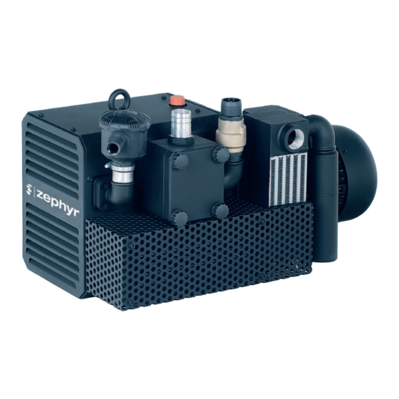
Set up and operation Set up and operation Setup Fig. 2 Pressure vacuum pump C-KLR 80 Vacuum connection Rotation direction plate Pressure connection Drive motor Cooling air inlet Motor data plate Cooling air outlet Compressed air aftercooler Oil fi lling point Suction fi... -
Page 13: Data Plate
Relief valves (Fig. 2/ZUV) and (Fig. 2/ZBD) are installed as standard to protect against overload.. Areas of application These contact free running claw pressure vacuum pumps models C-KLR 80 and C-KLR 140 are suitable for creating pressure and vacuum at the same time. Constant operation is permissible. -
Page 14: Installation
Installation Installation Preparing for installation Check the following points: • Machine freely accessible from all sides • Do not close ventilation grids and holes • Suffi cient room for installing and removing pipes and for maintenance work, particularly for install- ing and dismantling the machine •... -
Page 15: Connecting Pipes
Installation Connecting pipes a) Vacuum connection at (Fig. 2/A) and pressure connection at (Fig. 2/B). NOTICE Material damage resulting from the forces and torques of the pipes on the unit being too high. Only screw pipes in by hand. The pumping capacity of the machine is redu- ced if the suction pipe is too narrow and/or too long. -
Page 16: Filling With Lubricating Oil
Installation Filling with lubricating oil a) Fill the lubricating oil (for suitable types see „Maintenance“) for the gear wheels and bearings at the oil fi lling point (Fig. 2/H) up to the middle of the sight glass (Fig. 2/I). b) Close the oil fi lling point. Connecting the motor DANGER Danger of death if the electrical installation has... -
Page 17: Commissioning And Decommissioning
Commissioning and decommissioning Commissioning and decommissioning Commissioning WARNING Improper use May lead to severe or fatal injuries. Therefore be sure to obey the safety instructions. CAUTION Hot surfaces When the machine is at operating temperature the surface temperatures on the components (Fig. 2/ Q) may go above 70°C. -
Page 18: Checking The Rotation Direction
Commissioning and decommissioning 6.1.1 Checking the rotation direction The intended direction of rotation of the drive shaft is shown by the rotary direction arrow (Fig. 2/O) on the motor fl ange. a) Start the motor briefl y (max. two seconds) to check the direction of rotation. -
Page 19: Maintenance And Repair
Maintenance and repair Maintenance and repair DANGER Danger of death from touching live parts. Before maintenance work disconnect the machine by pressing the main switch or unplugging it and ensure that it cannot be turned on again. WARNING Hot surfaces During maintenance work there is the danger of getting burnt on hot components (Fig. -
Page 20: Changing The Oil
Maintenance and repair 7.2.1 Changing the oil Fig. 4 Changing the oil NOTICE Oil fi lling point Always change the oil when the machine is at Oil sight glass operating temperature and in an atmospherically ventilated area. Oil discharge point If it is not completely emptied the amount that can Oil recommendation plate be refi... -
Page 21: Air Fi Ltering
Maintenance and repair 7.2.2 Air fi ltering NOTICE Insuffi cient maintenance on the air fi lter The power of the machine lessens and damage may occur to the machine. The fi lter cartridges (Fig. 5/e) for intake air and (Fig. 5/f) for interim charging must be cleaned by blowing through from the inside out depending on how dirty they are. -
Page 22: Coupling
(Fig. 7/m, 8/m) off and ensure that it cannot be switched on again. C-KLR 80 Fig. 7 Coupling C-KLR 80 Undo the screws (Fig. 7/s ) on the motor fl ange. Remove the motor with the coupling half on the mo- Coupling sprocket tor side (Fig. -
Page 23: Reparatur/ Service
Maintenance and repair Reparatur/ Service a) For on site repair work the motor must be disconnected from the mains by a qualifi ed electrician so that it cannot be started up again accidentally. For repairs use the manufacturer, its branch offi ces or authorised dealers. Please contact the manufacturer for the address of the service centre responsible for you (see Manufac- turer‘s address). -
Page 24: Spare Parts
Maintenance and repair Spare parts Order spare parts in accordance with the: • Spare parts list : E 883/1 ➝ C-KLR 80 E 883/2 ➝ C-KLR 140 • Download the PDF fi le: http://www.gd-elmorietschle.com ➝ Downloads ➝ Product Documents ➝ C-Series ➝ Spare Parts •... -
Page 25: Malfunctions: Causes And Elimination
Malfunctions: Causes and elimination Malfunctions: Causes and elimination Fault Cause Troubleshooting Important Machine is switched Mains voltage/ Frequency Check by qualifi ed electrician Section 5.5 off by the motor pro- does not correspond with the tection switch motor data Connection to motor terminal board is not correct Motor protection switch is not set correctly... - Page 26 Service A relief valve is vibrating Replace the valve Section 7.4 Please contact Elmo Rietschle Service for other malfunctions or those that cannot be eliminated. www.gd-elmorietschle.com © Gardner Denver Schopfheim GmbH, Gardner Denver Deutschland GmbH...
-
Page 27: Technical Data
You will fi nd more technical data on the data sheet D 883 • Download the pdf fi le: D 883 ➝ C-KLR 80 / C-KLR 140 • Download the pdf fi le: http://www.gd-elmorietschle.com ➝ Downloads ➝ Product Documents ➝... - Page 28 Gardner Denver Schopfheim GmbH Roggenbachstraße 58 79650 Schopfheim · Deutschland Tel. +49 7622 392-0 Fax +49 7622 392-300 Elmo Rietschle is a brand of Gardner Denver‘s Industrial Products Division and part of Blower Operations.
- Page 29 Claw pressure/vacuum pump of the: Series: C-KLR Type: C-KLR 80, C-KLR 85, C-KLR 100, C-KLR 110, C-KLR 115, C-KLR 140 is conform to the regulations of the guideline indicated above. The following harmonized and national standards and specifications are applied: EN 1012-1:2010 Compressors and vacuum pumps —...
- Page 30 Safety declaration form 7.7025.003.17 for vacuum pumps and components Page 1 of 1 Gardner Denver Schopfheim GmbH Roggenbachstr. 58, 79650 Schopfheim Phone: +49/(0)7622/392-0 Fax: +49/(0)7622/392-300 Repairs and/or maintenance of vacuum pumps and components will only be carried out if a declaration has been filled in correctly and completely.
Need help?
Do you have a question about the C-KLR 80 and is the answer not in the manual?
Questions and answers