Panasonic CS-RE18JKE Service Manual
Hide thumbs
Also See for CS-RE18JKE:
- Operating instructions manual (9 pages) ,
- Operating instructions manual (56 pages)
Table of Contents
Advertisement
Quick Links
TABLE OF CONTENTS
1 Safety Precautions----------------------------------------------- 3
2 Specifications ----------------------------------------------------- 5
3 Features ------------------------------------------------------------- 8
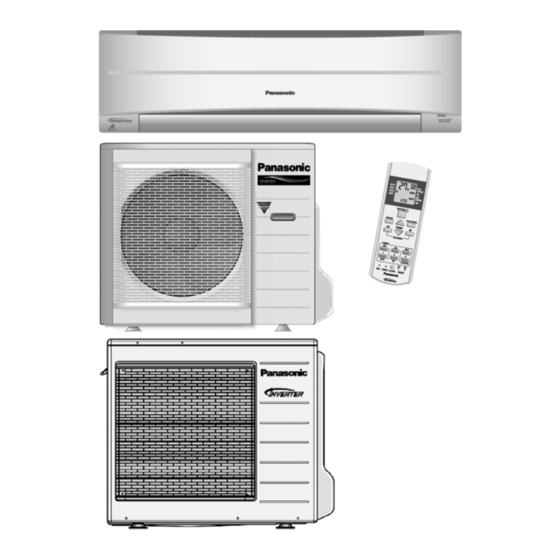
4 Location of Controls and Components ------------------- 9
4.1. Indoor Unit--------------------------------------------------- 9
4.2. Outdoor Unit ------------------------------------------------ 9
4.3. Remote Control -------------------------------------------- 9
Indoor Unit
CS-RE18JKE CU-RE18JKE
CS-RE24JKE CU-RE24JKE
PAGE
5 Dimensions ------------------------------------------------------- 10
5.1. Indoor Unit & Remote Control ------------------------ 10
5.2. Outdoor Unit----------------------------------------------- 11
6 Refrigeration Cycle Diagram -------------------------------- 13
7 Block Diagram --------------------------------------------------- 14
7.1. CS-RE18JKE CU-RE18JKE-------------------------- 14
7.2. CS-RE24JKE CU-RE24JKE-------------------------- 15
© Panasonic HA Air-Conditioning (M) Sdn. Bhd. 2008.
Unauthorized copying and distribution is a violation of law.
Order No. PHAAM0810055C2
Air Conditioner
Outdoor Unit
PAGE
Advertisement
Table of Contents

Related Manuals for Panasonic CS-RE18JKE


Summary of Contents for Panasonic CS-RE18JKE
-
Page 1: Table Of Contents
7 Block Diagram --------------------------------------------------- 14 4.2. Outdoor Unit ------------------------------------------------ 9 7.1. CS-RE18JKE CU-RE18JKE-------------------------- 14 4.3. Remote Control -------------------------------------------- 9 7.2. CS-RE24JKE CU-RE24JKE-------------------------- 15 © Panasonic HA Air-Conditioning (M) Sdn. Bhd. 2008. Unauthorized copying and distribution is a violation of law. - Page 2 8 Wiring Connection Diagram --------------------------------- 16 8.1. Indoor Unit ------------------------------------------------- 16 8.2. Outdoor Unit ----------------------------------------------- 17 9 Electronic Circuit Diagram----------------------------------- 19 9.1. Indoor Unit ------------------------------------------------- 19 9.2. Outdoor Unit ----------------------------------------------- 20 10 Printed Circuit Board ------------------------------------------ 22 10.1. Indoor Unit ------------------------------------------------- 22 10.2.
-
Page 3: Safety Precautions
1 Safety Precautions • Read the following “SAFETY PRECAUTIONS” carefully before perform any servicing. • Electrical work must be installed or serviced by a licensed electrician. Be sure to use the correct rating of the power plug and main circuit for the model installed. •... - Page 4 19. During installation, before run the compressor, confirm the refrigerant pipes are fixed. Operation of compressor without fixing the piping, setting the valves at open condition, a burst may occur and cause injury. 20. During pump down operation, stop the compressor before remove the refrigerant piping. When remove piping while valves at open condition, burst may occur and cause injury.
-
Page 5: Specifications
2 Specifications MODEL INDOOR CS-RE18JKE CS-RE24JKE OUTDOOR CU-RE18JKE CU-RE24JKE Performance Test Condition EUROVENT EUROVENT Phase, Hz Single, 50 Single, 50 Power Supply Min. Mid. Max. Min. Mid. Max. 0.90 5.00 6.00 0.90 6.80 8.10 Capacity BTU/h 3070 17100 20500 3070... - Page 6 MODEL INDOOR CS-RE18JKE CS-RE24JKE OUTDOOR CU-RE18JKE CU-RE24JKE Type Cross-Flow Fan Cross-Flow Fan Material ASG30K1 ASG30K1 Motor Type DC Motor DC Motor Input Power 94.8 85.1 Output Power Cool Heat 1040 1040 Cool 1040 1050 Heat 1120 1140 Cool 1160 1230...
- Page 7 MODEL INDOOR CS-RE18JKE CS-RE24JKE OUTDOOR CU-RE18JKE CU-RE24JKE Fin Material Aluminium (Pre Coat) Aluminium (Pre Coat) Fin Type Slit Fin Slit Fin Indoor Heat Row u Stage u FPI 2 u 15 u 19 2 u 15 u 21 Exchanger Size (W u H u L) 810 u 315 u 25.4...
-
Page 8: Features
3 Features • Inverter Technology - Wider output range - Energy saving - Quick Cooling - More precise temperature control • Environment Protection - Non-ozone depletion substances refrigerant (R410A) • Long Installation Piping - CS/CU-RE18JKE, long piping up to 20 meter - CS/CU-RE24JKE, long piping up to 30 meter •... -
Page 9: Location Of Controls And Components
4 Location of Controls and Components 4.1. Indoor Unit 4.2. Outdoor Unit 4.3. Remote Control... -
Page 10: Dimensions
5 Dimensions 5.1. Indoor Unit & Remote Control... -
Page 11: Outdoor Unit
5.2. Outdoor Unit 5.2.1. CU-RE18JKE... - Page 12 5.2.2. CU-RE24JKE...
-
Page 13: Refrigeration Cycle Diagram
6 Refrigeration Cycle Diagram... -
Page 14: Block Diagram
7 Block Diagram 7.1. CS-RE18JKE CU-RE18JKE... -
Page 15: Cs-Re24Jke Cu-Re24Jke
7.2. CS-RE24JKE CU-RE24JKE... -
Page 16: Wiring Connection Diagram
8 Wiring Connection Diagram 8.1. Indoor Unit... -
Page 17: Outdoor Unit
8.2. Outdoor Unit 8.2.1. CU-RE18JKE... - Page 18 8.2.2. CU-RE24JKE...
-
Page 19: Electronic Circuit Diagram
9 Electronic Circuit Diagram 9.1. Indoor Unit... -
Page 20: Outdoor Unit
9.2. Outdoor Unit 9.2.1. CU-RE18JKE... - Page 21 9.2.2. CU-RE24JKE...
-
Page 22: Printed Circuit Board
10 Printed Circuit Board 10.1. Indoor Unit 10.1.1. Main Printed Circuit Board... - Page 23 10.1.2. Power Printed Circuit Board 10.1.3. Indicator Printed Circuit Board...
-
Page 24: Outdoor Unit
10.2. Outdoor Unit 10.2.1. Main Printed Circuit Board 10.2.1.1. CU-RE18JKE... - Page 25 10.2.2. Main Printed Circuit Board 10.2.2.1. CU-RE24JKE...
- Page 26 10.2.3. Power Printed Circuit Board 10.2.3.1. CU-RE24JKE...
-
Page 27: Installation Instruction
11 Installation Instruction 11.1. Select the Best Location 11.1.3. Indoor/Outdoor Unit Installation Diagram 11.1.1. Indoor Unit • Do not install the unit in excessive oil fume area such as kitchen, workshop and etc. • There should not be any heat source or steam near the unit. •... -
Page 28: Indoor Unit
11.2. 11.2.2. To Drill a Hole in the Wall and Install Indoor Unit a Sleeve of Piping 11.2.1. How to Fix Installation Plate 1. Insert the piping sleeve to the hole. The mounting wall shall be strong and solid enough to prevent 2. - Page 29 1. For the right rear piping 2. For the right and right bottom piping 3. For the embedded piping...
-
Page 30: Connect The Cable To The Indoor Unit
(This can be used for left rear piping and left bottom piping also.) 11.2.4. Connect the Cable to the Indoor Unit 1. The inside and outside connecting cable can be connected without removing the front grille. 2. Connecting cable between indoor unit and outdoor unit shall be approved polychloroprene sheathed 4 u 1.5 mm flexible cord, type designation 245 IEC 57 or heavier cord. - Page 31 CUTTING AND FLARING THE PIPING 1. Please cut using pipe cutter and then remove the burrs. 2. Remove the burrs by using reamer. If burrs is not removed, gas leakage may be caused. Turn the piping end down to avoid the metal powder entering the pipe. 3.
-
Page 32: Outdoor Unit
11.3. Outdoor Unit 11.3.1. Install the Outdoor Unit • After selecting the best location, start installation according to Indoor/Outdoor Unit Installation Diagram. 1. Fix the unit on concrete or rigid frame firmly and horizontally by bolt nut (ø10 mm). 2. When installing at roof, please consider strong wind and earthquake. Please fasten the installation stand firmly with bolt or nails. -
Page 33: Evacuation Of The Equipment
11.3.3. Evacuation of the Equipment WHEN INSTALLING AN AIR CONDITIONER, BE SURE TO EVACUATE THE AIR INSIDE THE INDOOR UNIT AND PIPES in the following procedure. 1. Connect a charging hose with a push pin to the Low side of a charging set and the service port of the 3-way valve. •... -
Page 34: Pipe Insulation
5. Secure the power supply cord and connecting cable onto the control board with the holder. 6. Attach the control board cover back to the original position with screw. 7. For wire stripping and connection requirement, refer to instruction of indoor unit. This equipment must be properly earthed. -
Page 35: Operation And Control
12 Operation and Control 12.1. Basic Function Inverter control, which equipped with a microcomputer in determining the most suitable operating mode as time passes, automatically adjusts output power for maximum comfort always. In order to achieve the suitable operating mode, the microcomputer maintains the set temperature by measuring the temperature of the environment and performing temperature shifting. -
Page 36: Automatic Operation
12.1.5. Automatic Operation • This mode can be set using remote control and the operation is decided by remote control setting temperature, remote control operation mode, indoor intake air temperature and outdoor air temperature. • During operation mode judgment, indoor fan motor (with speed of Lo-) and outdoor fan motor are running for 30 seconds to detect the indoor intake and outdoor air temperature. -
Page 37: Airflow Direction
[Heating] • According to indoor pipe temperature, automatic heating fan speed is determined as follows. B. Feedback control • Immediately after the fan motor started, feedback control is performed once every second. • During fan motor on, if fan motor feedback 2550 rpm or <... - Page 38 1. Automatic vertical airflow direction can be set using remote control; the vane swings up and down within the angles as stated above. For heating mode operation, the angle of the vane depends on the indoor heat exchanger temperature as Figure 1 below.
-
Page 39: On Timer Control
12.3. ON Timer Control ON timer can be set using remote control, the unit with timer set will start operate earlier than the setting time. This is to provide a comfortable environment when reaching the set ON time. 60 minutes before the set time, indoor (at fan speed of Lo-) and outdoor fan motor start operate for 30 seconds to determine the indoor intake air temperature and outdoor air temperature in order to judge the operation starting time. -
Page 40: Protection Control
13 Protection Control 13.1. Protection Control For All Operations 13.1.1. Time Delay Safety Control 1. The compressor will not start for three minutes after stop of operation. 2. This control is not applicable if the power supply is cut off and on again or after 4-way valve deices condition. 13.1.2. -
Page 41: Compressor Tank Temperature Rise Protection Control
13.1.5. Compressor Overheating Prevention Control Instructed frequency for compressor operation will be regulated by compressor discharge temperature. The changes of frequency are as below figure. If compressor discharge temperature exceeds 112qC, compressor will be stop, occurs 4 times per 20 minutes, timer LED will be blinking (“F97”... -
Page 42: Protection Control For Cooling & Soft Dry Operation
13.1.9. Low Frequency Protection Control 2 • When all the below conditions comply, the compressor frequency will change to lower frequency. Temperature, T, for: Cooling/Soft Dry Heating Indoor intake air (qC) — T < 15 or T Outdoor air (qC) T <... -
Page 43: Freeze Prevention Control
13.2.5. Freeze Prevention Control 1 1. When indoor heat exchanger temperature is lower than 0qC continuously for six minutes, compressor will stop operating. 2. Compressor will resume its operation three minutes after the indoor heat exchanger is higher than 13qC. 3. -
Page 44: Protection Control For Heating Operation
13.3. Protection Control For Heating Operation 13.3.1. Intake Air Temperature Control Compressor will operate at maximum frequency if below conditions occur: 1. When the indoor intake air temperature is 30qC or above. 13.3.2. Outdoor Air Temperature Control The maximum current value is regulated when the outdoor air temperature rises above 14qC in order to avoid compressor overloading. -
Page 45: Servicing Mode
14 Servicing Mode 14.1. Auto OFF/ON Button 1. AUTO OPERATION MODE The Auto operation will be activated immediately once the Auto OFF/ON button is pressed. This operation can be used to operate air conditioner with limited function if remote control is misplaced or malfunction. 2. -
Page 46: Remote Control Button
4. REMOTE CONTROL RECEIVING SOUND OFF/ON MODE The Remote Control Receiving Sound OFF/ON Mode will be activated if the Auto OFF/ON button is pressed continuously for more than 16 seconds (4 “beep” sounds will occur at 16th seconds to identify the Remote Control Receiving Sound Off/On Mode is in standby condition) and press “AC Reset”... -
Page 47: Troubleshooting Guide
15 Troubleshooting Guide 15.1. Refrigeration Cycle System In order to diagnose malfunctions, make sure that there are no electrical problems before inspecting the refrigeration cycle. Such problems include insufficient insulation, problem with the power source, malfunction of a compressor and a fan. The normal outlet air temperature and pressure of the refrigeration cycle depends on various conditions, the standard values for them are shown in the table on the right. -
Page 48: Relationship Between The Condition Of The Air Conditioner And Pressure And Electric Current
15.2. Relationship Between The Condition Of The Air Conditioner And Pressure And Electric Current Cooling Mode Heating Mode Condition of the air conditoner Low Pressure High Pressure Electric current Low Pressure High Pressure Electric current during operation during operation Insufficient refrigerant (gas leakage) Clogged capillary tube or Strainer... -
Page 49: Breakdown Self Diagnosis Function
15.3. Breakdown Self Diagnosis Function 15.3.1. Self Diagnosis Function (Three Digits Alphanumeric Code) • Once abnormality has occurred during operation, the unit 7. The breakdown diagnosis mode will be canceled will stop its operation, and Timer LEDs blink. unless pressing the CHECK button continuously for 5 •... -
Page 50: Error Codes Table
15.4. Error Codes Table Diagnosis Abnormality Emergency Abnormality / Protection control Primary location to verify display Judgement operation No abnormality detected — Normal operation — Indoor / outdoor abnormal > 1 min after starting Indoor fan operation • Internal / external cable connections communication operation only... -
Page 51: Self-Diagnosis Method
15.5. Self-diagnosis Method 15.5.1. H11 (Indoor/Outdoor Abnormal Communication) Malfunction Decision Conditions • During startup and operation of cooling and heating, the data received from outdoor unit in indoor unit signal transmission is checked whether it is normal. Malfunction Caused • Faulty indoor unit PCB. •... - Page 52 15.5.2. H12 (Indoor/Outdoor Capacity Rank Mismatched) Malfunction Decision Conditions • During startup, error code appears when different types of indoor and outdoor units are interconnected. Malfunction Caused • Wrong models interconnected. • Wrong indoor unit or outdoor unit PCBs mounted. •...
- Page 53 15.5.3. H14 (Indoor Intake Air Temperature Sensor Abnormality) Malfunction Decision Conditions • During startup and operation of cooling and heating, the temperatures detected by the indoor intake air temperature sensor are used to determine sensor errors. Malfunction Caused • Faulty connector connection. •...
- Page 54 15.5.4. H15 (Compressor Temperature Sensor Abnormality) Malfunction Decision Conditions • During startup and operation of cooling and heating, the temperatures detected by the outdoor compressor temperature sensor are used to determine sensor errors. Malfunction Caused • Faulty connector connection. • Faulty sensor. •...
- Page 55 15.5.5. H16 (Outdoor Current Transformer Open Circuit) Malfunction Decision Conditions • A current transformer (CT) is detected by checking the compressor running frequency ( rated frequency) and CT detected input current (less than 0.65A) for continuously 20 seconds. Malfunction Caused •...
- Page 56 15.5.6. H19 (Indoor Fan Motor – DC Motor Mechanism Locked) Malfunction Decision Conditions • The rotation speed detected by the Hall IC during fan motor operation is used to determine abnormal fan motor (feedback of rotation > 2550rpm or < 50rpm). Malfunction Caused •...
- Page 57 15.5.7. H23 (Indoor Pipe Temperature Sensor Abnormality) Malfunction Decision Conditions • During startup and operation of cooling and heating, the temperatures detected by the indoor heat exchanger temperature sensor are used to determine sensor errors. Malfunction Caused • Faulty connector connection. •...
- Page 58 15.5.8. H27 (Outdoor Air Temperature Sensor Abnormality) Malfunction Decision Conditions • During startup and operation of cooling and heating, the temperatures detected by the outdoor air temperature sensor are used to determine sensor errors. Malfunction Caused • Faulty connector connection. •...
- Page 59 15.5.9. H28 (Outdoor Pipe Temperature Sensor Abnormality) Malfunction Decision Conditions • During startup and operation of cooling and heating, the temperatures detected by the outdoor pipe temperature sensor are used to determine sensor errors. Malfunction Caused • Faulty connector connection. •...
- Page 60 15.5.10. H30 (Compressor Discharge Temperature Sensor Abnormality) Malfunction Decision Conditions • During startup and operation of cooling and heating, the temperatures detected by the outdoor discharge pipe temperature sensor are used to determine sensor errors. Malfunction Caused • Faulty connector connection. •...
- Page 61 15.5.11. H33 (Unspecified Voltage between Indoor and Outdoor) Malfunction Decision Conditions • The supply power is detected for its requirement by the indoor/outdoor transmission. Malfunction Caused • Wrong models interconnected. • Wrong indoor unit and outdoor unit PCBs used. • Indoor unit or outdoor unit PCB defective. Troubleshooting...
- Page 62 15.5.12. H58 (Patrol Sensor Abnormality) Malfunction Decision Conditions • If Patrol sensor feedback is 0V or 5V continuous for 6 hours. • Error will display only when the Patrol operation is ON. Malfunction Caused • Faulty connector connection. • Faulty Patrol sensor. Troubleshooting...
- Page 63 15.5.13. H97 (Outdoor Fan Motor – DC Motor Mechanism Locked) Malfunction Decision Conditions • The rotation speed detected by the Hall IC during fan motor operation is used to determine abnormal fan motor. Malfunction Caused • Operation stops due to short circuit inside the fan motor winding. •...
- Page 64 15.5.14. H98 (Indoor High Pressure Protection) Error Code will not display (no Timer LED blinking) but store in EEPROM Malfunction Decision Conditions • During heating operation, the temperature detected by the indoor pipe temperature sensor is above 60qC. Malfunction Caused •...
-
Page 65: H99 (Indoor Freeze Prevention Protection: Cooling Or Soft Dry)
15.5.15. H99 (Indoor Freeze Prevention Protection: Cooling or Soft Dry) Error code will not display (no TIMER LED blinking) but store in EEPROM Malfunction Decision Conditions • Freeze prevention control takes place (when indoor pipe temperature is lower than 2qC). Malfunction Caused •... - Page 66 15.5.16. F11 (4-way valve Abnormality) Malfunction Decision Conditions • When heating operation, when indoor pipe temperature is below 10qC. • When cooling operation, when indoor pipe temperature is above 45qC. Malfunction Caused • Connector in poor contact. • Faulty sensor. •...
- Page 67 15.5.17. F90 (Power Factor Correction Protection) Malfunction Decision Conditions • During startup and operation of cooling and heating, when Power Factor Correction (PFC) protection circuitry at the outdoor unit main PCB senses abnormal high DC voltage level. Malfunction Caused • DC voltage peak due to power supply surge. •...
- Page 68 15.5.18. F91 (Refrigeration Cycle Abnormality) Malfunction Decision Conditions • During cooling, compressor frequency = Fcmax. • During heating, compressor frequency > Fhrated. • During cooling and heating operation, running current: 0.65A < I < 1.65A. • During cooling, indoor intake - indoor pipe < 4qC. •...
- Page 69 15.5.19. F93 (Compressor Rotation Failure) Malfunction Decision Conditions A compressor rotation failure is detected by checking the compressor running condition through the position detection circuit. Malfunction Caused • Compressor terminal disconnect. • Outdoor PCB malfunction. Troubleshooting...
- Page 70 15.5.20. F95 (Cooling High Pressure Abnormality) Malfunction Decision Conditions During operation of cooling, when outdoor unit heat exchanger high temperature data (61qC) is detected by the outdoor pipe temperature sensor. Malfunction Caused • Outdoor pipe temperature rise due to short circuit of hot discharge air flow. •...
- Page 71 15.5.21. F96 (IPM Overheating) Malfunction Decision Conditions During operating of cooling and heating, when IPM temperature data (100qC) is detected by the IPM temperature sensor. Multi Models Only • Compressor Overheating: During operation of cooling and heating, when the compressor OL is activated. •...
- Page 72 15.5.22. F97 (Compressor Overheating) Malfunction Decision Conditions During operation of cooling and heating, when compressor tank temperature data (112°C) is detected by the compressor tank temperature sensor. Malfunction Caused • Refrigerant shortage (refrigerant leakage). • 2/3 way valve closed. • Detection error due to faulty compressor tank temperature sensor. Troubleshooting...
- Page 73 15.5.23. F98 (Input Over Current Detection) Malfunction Decision Conditions During operation of cooling and heating, when an input over-current (16.8A) is detected by checking the input current value being detected by current transformer (CT) with the compressor running. Malfunction Caused •...
- Page 74 15.5.24. F99 (Output Over Current Detection) Malfunction Decision Conditions During operation of cooling and heating, when an output over-current (18.5A) is detected by checking the current that flows in the inverter DC peak sensing circuitry. Malfunction Caused • DC peak due to compressor failure. •...
-
Page 75: Disassembly And Assembly Instructions
16 Disassembly and Assembly Instructions WARNING High Voltage are generated in the electrical parts area by the capacitor. Ensure that the capacitor has discharged sufficiently before proceeding with repair work. Failure to heed this caution may result in electric shocks. 16.1. - Page 76 16.1.3. To remove power electronic controller...
- Page 77 16.1.4. To remove discharge grille 16.1.5. To remove control board...
- Page 78 16.1.6. To remove cross flow fan and indoor fan motor...
-
Page 80: Outdoor Electronic Controller Removal Procedure (Re18Jk)
16.2. Outdoor Electronic Controller Removal Procedure (RE18JK) 1. Remove the 4 screws of the Top Panel. 4. Remove the Control Board. Fig. 4 5. Remove the 8 screws of the Electronic Controller. Fig. 1 2. Remove the 10 screws of the Front Panel. Fig. -
Page 81: Technical Data
17 Technical Data 17.1. Operation Characteristics 17.1.1. CS-RE18JKE CU-RE18JKE Cooling Characteristic at Different Outdoor Air Temperature Condition Indoor room temperature: 27/19qC Remote control setting: HI FAN, COOL 16qC Compressor frequency: F Voltage: 230 V... - Page 82 Cooling Characteristic at Different Piping Length Condition Indoor room temperature: 27/19qC, 35/-qC Remote control setting: HI FAN, COOL 16qC Compressor frequency: F Voltage: 230 V...
- Page 83 Heating Characteristic at Different Outdoor Air Temperature Condition Indoor room temperature: 20/-qC Remote control setting: HI FAN, HEAT 30qC Compressor frequency: F Voltage: 230 V...
- Page 84 Heating Characteristic at Different Piping Length Condition Indoor room temperature: 20/-qC, 7/6qC Remote control setting: HI FAN, HEAT 30qC Compressor frequency: F Voltage: 230 V...
- Page 85 17.1.2. CS-RE24JKE CU-RE24JKE Cooling Characteristic at Different Outdoor Air Temperature Condition Indoor room temperature: 27/19qC Remote control setting: HI FAN, COOL 16qC Compressor frequency: F Voltage: 230 V...
- Page 86 Cooling Characteristic at Different Piping Length Condition Indoor room temperature: 27/19qC, 35/-qC Remote control setting: HI FAN, COOL 16qC Compressor frequency: F Voltage: 230 V...
- Page 87 Heating Characteristic at Different Outdoor Air Temperature Condition Indoor room temperature: 20/-qC Remote control setting: HI FAN, HEAT 30qC Compressor frequency: F Voltage: 230 V...
- Page 88 Heating Characteristic at Different Piping Length Condition Indoor room temperature: 20/-qC, 7/6qC Remote control setting: HI FAN, HEAT 30qC Compressor frequency: F Voltage: 230 V...
-
Page 89: Sensible Capacity Chart
17.2. Sensible Capacity Chart CS-RE18JKE CU-RE18JKE Outdoor Temp. (qC) Indoor wet bulb temp. 17.0qC 4.96 3.76 1.35 4.64 3.61 1.45 4.31 3.47 1.55 3.92 3.29 1.67 19.0qC 5.00 1.47 19.5qC 5.45 3.94 1.37 5.09 3.78 1.48 4.74 3.64 1.58 4.31 3.47... -
Page 90: Exploded View And Replacement Parts List
18 Exploded View and Replacement Parts List 18.1. Indoor Unit... - Page 91 <Model: CS-RE18JKE CS-RE24JKE> REF NO. PART NAME & DESCRIPTION QTY. CS-RE18JKE CS-RE24JKE REMARKS CHASSY COMPLETE CWD50C1623 FAN MOTOR L6CBYYYL0038 CROSS FLOW FAN COMPLETE CWH02C1077 BEARING ASS’Y CWH64K007 SCREW - CROSS FLOW FAN CWH551146 GENERATOR COMPLETE — — EVAPORATOR CWB30C2900 CWB30C2777...
- Page 92 REF NO. PART NAME & DESCRIPTION QTY. CS-RE18JKE CS-RE24JKE REMARKS INSTALLATION INSTRUCTION CWF613910 INSTALLATION INSTRUCTION CWF613911 INSTALLATION INSTRUCTION CWF613912 INSTALLATION INSTRUCTION CWF613913 INSTALLATION INSTRUCTION CWF613914 INSTALLATION INSTRUCTION CWF613915 INSTALLATION INSTRUCTION CWF613916 SUPER ALLERU BUSTER FILTER CWD00C1263 (Note) • All parts are supplied from PHAAM, Malaysia (Vendor Code: 00029488).
-
Page 93: Cu-Re18Jke
18.2. CU-RE18JKE Note: The above exploded view is for the purpose of parts disassembly and replacement. The non-numbered parts are not kept as standard service parts. - Page 94 REF NO. PART NAME & DESCRIPTION QTY. CU-RE18JKE REMARKS CHASSY ASS’Y CWD50K2085 ANTI-VIBRATION BUSHING CWH50077 COMPRESSOR 5CS130XAD04 NUT-COMPRESSOR MOUNT CWH56000J SOUND PROOF MATERIAL CWG302302 FAN MOTOR BRACKET CWD541054 FAN MOTOR CWA981166J SCREW - FAN MOTOR BRACKET CWH551217 SCREW - FAN MOTOR MOUNT CWH551106J PROPELLER FAN ASSY CWH03K1016...
-
Page 95: Cu-Re24Jke
18.3. CU-RE24JKE Note: The above exploded view is for the purpose of parts disassembly and replacement. The non-numbered parts are not kept as standard service parts. - Page 96 REF NO. PART NAME & DESCRIPTION QTY. CU-RE24JKE REMARKS CHASSY ASS’Y CWD52K1190 ANTI - VIBRATION BUSHING CWH50055 PACKING CWB81043 COMPRESSOR 5KD240XAF21 NUT - COMPRESSOR MOUNT CWH561049 FAN MOTOR BRACKET CWD541126 FAN MOTOR CWA951636 SCREW - FAN MOTOR BRACKET CWH551217 SCREW - FAN MOTOR MOUNT CWH551040J PROPELLER FAN ASS’Y CWH001019...
Need help?
Do you have a question about the CS-RE18JKE and is the answer not in the manual?
Questions and answers