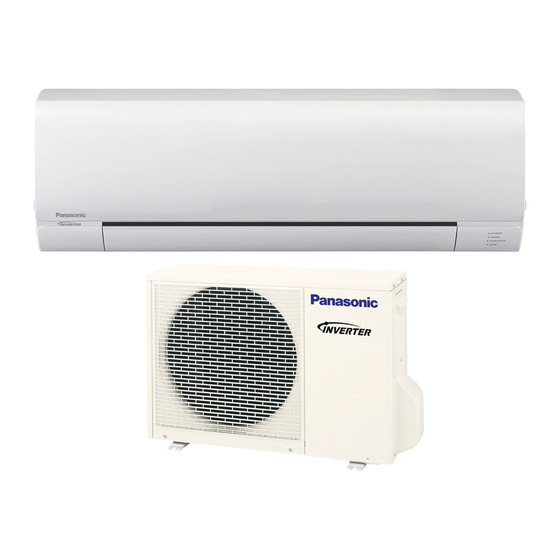
Panasonic CS-RE9SKUA Installation Manual
Hide thumbs
Also See for CS-RE9SKUA:
- Service manual (138 pages) ,
- Operating instructions manual (24 pages)
Advertisement
Quick Links
Installation Manual
AUTO
FAN
HEAT
SPEED
AIR
COOL
SWING
DRY
FAN
OFF/ON
MODE
TEMP
TEMP
AIR SWING
POWERFUL/
/
FAN SPEED
QUIET
TIMER
ON
SET
1
1
2
2
3
3
OFF
CANCEL
AC
RC
SET CHECK CLOCK
CHE
RESET
AUTO
FAN
SPEED
HEAT
COOL
DRY
AIR
SWING
FAN
OFF/ON
MODE
TEMP
POWERFUL/
/
AIR SWING
QUIET
FAN SPEED
TIMER
TIMER
ON
SET
1
1
2
2
3
3
OFF
OFF
CANCEL
CANCEL
AC
RC
SET CHECK CLOCK
RESET
Advertisement

Summary of Contents for Panasonic CS-RE9SKUA
- Page 1 Installation Manual AUTO HEAT SPEED COOL SWING OFF/ON MODE TEMP TEMP AIR SWING POWERFUL/ FAN SPEED QUIET TIMER CANCEL SET CHECK CLOCK RESET AUTO SPEED HEAT COOL SWING OFF/ON MODE TEMP POWERFUL/ AIR SWING QUIET FAN SPEED TIMER TIMER CANCEL CANCEL SET CHECK CLOCK RESET...
- Page 2 11.1 Select the Best Location Indoor/Outdoor Unit Installation Diagram Piping direction Do not bend up (Front side) drain hose Right Rear Left Right Left bottom Rear Left bottom Installation parts you should purchase ( ) Installation plate 1 Bushing-Sleeve ( ) Sleeve ( ) "...
- Page 3 11.2 Indoor Unit Wall Wall Wall More than More than Indoor unit More than screw " (128 mm) " " (241.5 mm) (241.5 mm) Installation plate Measuring Tape For best strength of 5 1/16" " INDOOR unit installation, (128 mm) (128 mm) it is highly recommended to locate “...
-
Page 4: Table Of Contents
Piping Piping Shock absorber 11.2.3.1 For the right rear piping 11.2.3.2 For the right bottom piping 11.2.3.3 For the embedded piping Step-1 Step-2 Step-3 Step-4 Step-5 Step-6 Step-7 Step-8... - Page 5 • • •...
- Page 6 11.2.4.1 Wire Stripping, Connecting Requirement Wire stripping Conductor not Conductor Conductor fully inserted fully inserted over inserted Indoor/outdoor connection terminal board 7/32” (5 mm) No loose strand or more when inserted ACCEPT PROHIBITED PROHIBITED (gap between wires)
- Page 7 11.2.4.2 Cutting and flaring the piping...
- Page 8 11.3 Outdoor Unit 11.3.2.1 Connecting the piping to indoor 11.3.2.2 Connecting the piping to outdoor 11.3.2.3 Gas Leak Checking...
- Page 10 11.3.3.1 Connect the Cable to the Outdoor Unit Terminal Terminal 11.3.3.2 Piping Insulation...
- Page 11 12.1 Select the Best Location Indoor/Outdoor Unit Installation Diagram Piping direction Do not bend up (Front side) drain hose Right Rear Left Right Left bottom Rear Left bottom Installation parts you should purchase ( ) Installation plate Bushing-Sleeve ( ) Sleeve ( ) "...
- Page 12 12.2 Indoor Unit Wall Wall Wall More than More than Indoor unit More than screw " (128 mm) " " (241.5 mm) (241.5 mm) Installation plate Measuring Tape For best strength of 5 1/16" " INDOOR unit installation, (128 mm) (128 mm) it is highly recommended to locate “...
-
Page 13: Step
Piping Piping Shock absorber 12.2.3.1 For the right rear piping 12.2.3.2 For the right bottom piping 12.2.3.3 For the embedded piping Step-1 Step-2 Step-3 Step-4 Step-5 Step-6 Step-7 Step-8... -
Page 14: Step
• • •... -
Page 15: Step
12.2.4.1 Wire Stripping, Connecting Requirement Wire stripping Conductor not Conductor Conductor fully inserted fully inserted over inserted Indoor/outdoor connection terminal board 7/32” (5 mm) No loose strand or more when inserted ACCEPT PROHIBITED PROHIBITED (gap between wires) -
Page 16: Step
12.2.4.2 Cutting and flaring the piping... -
Page 17: Step
12.3 Outdoor Unit 12.3.2.1 Connecting the piping to indoor 12.3.2.2 Connecting the piping to outdoor 12.3.2.3 Gas Leak Checking... -
Page 19: Step
12.3.3.1 Connect the Cable to the Outdoor Unit Terminal Terminal... -
Page 20: Step
12.3.3.2 Piping Insulation...


Need help?
Do you have a question about the CS-RE9SKUA and is the answer not in the manual?
Questions and answers