Table of Contents
Advertisement
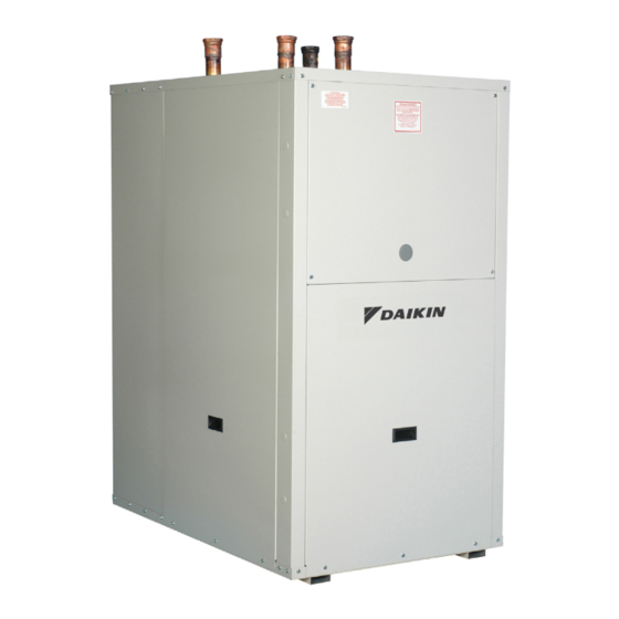
Daikin Water to Water Source Heat Pumps
3 to 35 Tons with R-410A
WRA - Heating and Cooling Models
WHA - Heating Only Models
WCA - Cooling Only Models
©2013 Daikin Applied • www.DaikinAP.com • (800) 432-1342
Installation and Maintenance Data
IM 1072-1
Group: WSHP
Part Number:
667691802
Date: October 2013
Advertisement
Table of Contents

Subscribe to Our Youtube Channel
Related Manuals for Daikin WRA


Summary of Contents for Daikin WRA
- Page 1 Date: October 2013 Daikin Water to Water Source Heat Pumps 3 to 35 Tons with R-410A WRA - Heating and Cooling Models WHA - Heating Only Models WCA - Cooling Only Models ©2013 Daikin Applied • www.DaikinAP.com • (800) 432-1342...
-
Page 2: Table Of Contents
(Continued) 208-230/60/3, Unit Sizes 120, 150, 180, 240 Safe Operation Rules ............4 and 300 ................23 Electrical Data ..............5 Legend ................24 WRA, WHA, WCA 036 – 420 ..........5 Control ................25 Installation ................6 Optional Low Temperature Control Board "LTC" – 3 Phase, Pre-Installation and Code Requirements ......6 Unit Sizes 120, 150, 180, 240 and 300......25... -
Page 3: Product Nomenclature
FS = Adjustable for Geothermal and Boiler/Tower Application SL = Three Lights-Compressor-1, Compressor-2, Compressor fault NOTE For illustration purposes only. Not all options available with all models. Please consult your local Daikin Representative for specific availability. IM 1072-1 Water to Water Source Heat Pumps... -
Page 4: Safety Information
Safety Information Safe Operation Rules Danger Label White lettering on a black background except the word Installation and maintenance are to be performed only by DANGER which is white with a red background. qualified personnel who are familiar with and in compliance with state, local and national codes and regulations, and experienced with this type of equipment. -
Page 5: Electrical Data
Electrical Data WRA, WHA, WCA 036 – 420 Table 1: Electrical data Compressor Maximum Max. Circuit Voltage Minimum Circuit Unit Size Voltage/Hz/Ph Total Unit FLA Fuse HACR Breaker Min./Max. Ampacity Quantity RLA (each) LRA (each) Breaker 208-230/60/1 16.7 79.0 33.4 197/253 20.9... -
Page 6: Installation
Installation Pre-Installation and Code Requirements If water hammer should occur during start-up or shut down, slow closing diaphragm type solenoid valves should be used. After removing the unit from the carton, immediately remove Placing the solenoid valve on the outlet side of the system helps the panels and inspect for any damage that might have occurred relieve this situation. -
Page 7: Applications
Applications Cooling Tower/ Boiler Application Closed Loop Earth Coupled Application Closed Loop Cooling Tower and Boiler Loop System temperature is Earth coupled closed loop systems should follow the same usually maintained between 55°F and 90°F. In the cooling International Ground Source Heat Pump Association guidelines mode, heat is rejected from the unit into the source water loop. -
Page 8: Start Up
12. Adjust thermostat to correct mode and set to maintain desired temperature. 13. Instruct the equipment owner/operator of correct thermostat and system operation. 14. Be certain to complete and forward the warranty papers to Daikin . Page 8 of 44 Water to Water Source Heat Pumps IM 1072-1... -
Page 9: Dimensional Data
Dimensional Data WRA, WCA, WHA – Size 036-072 Dimensions - Size 036 Dimensions (in.) Pipe Size (FPT) Connection Size Auxiliary Load Domestic Control Electric Electric Source Hot Water 28⅛ 28⅛ 1¾ 6⅜ 11⅞ 17⅛ 1½ 14⅞ 10⅝ 8⅝ 1/2" KO 3/4"... -
Page 10: Wra, Wca, Wha - Size 120-180
Dimensional Data WRA, WCA, WHA – Size 120-180 Dimensions - Size 120 – 150 Dimensions (in.) Water Connection Size Load Source FPT 26¼ 19½ 12¼ 4½ 8⅜ 22¼ 4⅜ 18¾ 22⅛ 29¾ 1½" Dimensions - Size 180 Dimensions (in.) Water Connection Size Load Source FPT 26¼... -
Page 11: Wra, Wca, Wha - Size 240-420
Dimensional Data WRA, WCA, WHA – Size 240-420 Dimensions - Size 240 – 420 Dimensions (in.) Water Connection Size Load Source FPT 20⅞ 16½ 4⅞ 22½ 27½ 63⅛ 22⅛ 52⅛ 44⅛ 2" IM 1072-1 Water to Water Source Heat Pumps... -
Page 12: Engineering Data
Engineering Data Physical Data Table 3: WRA, WHA, WCA 036 – 420 Cabinet Dimensions (in.) Unit Weight (lb.) Water Connections (in.) Factory Refrigerant Unit Size Charge Per Cicuit (lb.) Width Depth Height Operating Shipping 28.125 28.125 19.00 2.80 0.75 28.125 28.125... -
Page 13: Antifreeze Correction
Engineering Data Antifreeze Correction Heating Capacity Cooling Capacity Antifreeze Pessure Drop Load Source Load Source Type Percent 90°F EWT 30°F EWT 45°F EWT 90°F EWT 30°F EWT Water 1.000 1.000 1.000 1.000 1.000 0.991 0.973 0.975 0.991 1.075 0.979 0.943 0.946 0.979 1.163... -
Page 14: Wiring Diagram
Wiring Diagram 208-230/60/1, Unit Sizes 036, 048, 060 and 072 Note: See wiring diagram legend on page BL-14 BL-14 HRPR R-14 (WHEN USED) (WHEN USED) BK-14 (OPTIONAL) COMPRESSOR WIRE SIZE TABLE UNIT WIRE SIZE (AWG) SPLICE when necessary MODEL 4 (L2) R-14 R-14 (OPTIONAL) -
Page 15: Legend
Wiring Diagram Legend 208-230/60/1, Unit Sizes 036, 048, 060 and 072 LEGEND WIRE COLOR LEGEND BLACK PINK FUNCTIONAL LINE DESCRIPTION DESIGNATION NUMBER BLUE PR: PURPLE OPTIONAL INDICATOR LIGHT - COMPRESSOR ON BR: BROWN COMPRESSOR CONTACTOR GREEN WHITE CRANKCASE HEATER ORANGE YELLOW COMPRESSOR CONTROL MODULE NOTES:... -
Page 16: Control
Control Optional Low Temperature Control Board example, you set the temperature to 20°F. The output relays will de-energize when the sensor temperature drops below 20°F. "LTC" – 208-230/60/1, Unit Sizes 036, 048, The control will re-energize the output relays when the sensor 060 and 072 temperature rises above 22.5°F. -
Page 17: Compressor Control Module Functional Operation - 208-230/60/1, Unit Sizes 036, 048, 060 And 072
Control Compressor Control Module Functional Normal Cycle A normal cycle will begin with 24 VAC applied to the R and Operation – 208-230/60/1, Unit Sizes 036, C terminals on the circuit board. Once the control is powered up, 048, 060 and 072 the processor will read the Y signal to determine if it is calling. -
Page 18: Wiring Diagram
Wiring Diagram 208-230/60/3, Unit Sizes 036, 048, 060 and 072 Note: See wiring diagram legend on page HRPR R-14 (OPTIONAL) (WHEN USED) G-14 (WHEN USED) BK-14 Splice when PM is used R-14 5 (L3) COMPRESSOR WIRE SIZE TABLE UNIT WIRE SIZE (AWG) BL-14 4 (L2) MODEL... -
Page 19: Legend
Wiring Diagram Legend 208-230/60/3, Unit Sizes 036, 048, 060 and 072 LEGEND WIRE COLOR LEGEND FUNCTIONAL LINE DESCRIPTION BLACK PINK DESIGNATION NUMBER BLUE PR: PURPLE OPTIONAL INDICATOR LIGHT - COMPRESSOR ON BR: BROWN COMPRESSOR CONTACTOR GREEN WHITE CRANKCASE HEATER ORANGE YELLOW COMPRESSOR CONTROL MODULE NOTES:... -
Page 20: Control
Control Optional Low Temperature Control Board example, you set the temperature to 20°F. The output relays will de-energize when the sensor temperature drops below 20°F. "LTC" – 208-230/60/3, Unit Sizes 036, 048, The control will re-energize the output relays when the sensor 060 and 072 temperature rises above 22.5°F. -
Page 21: Compressor Control Module Functional Operation - 208-230/60/3, Unit Sizes 036, 048, 060 And 072
Control Compressor Control Module Functional Normal Cycle A normal cycle will begin with 24 VAC applied to the R and Operation – 208-230/60/3, Unit Sizes 036, C terminals on the circuit board. Once the control is powered up, 048, 060 and 072 the processor will read the Y signal to determine if it is calling. -
Page 22: Wiring Diagram
Wiring Diagram 208-230/60/3, Unit Sizes 120, 150, 180, 240 and 300 R-14 BL-14 BK-14 COMPRESSOR WIRE SIZE TABLE UNIT WIRE SIZE (AWG) MODEL 208/230 VOLT 460 & 575 VOLT 5 (L3) 4 (L2) (OPTIONAL) 3 (L1) CCH1 SPLICE (OPTIONAL) BL-14 BL-14 BK-14 CCH2... -
Page 23: (Continued) 208-230/60/3, Unit Sizes 120, 150, 180, 240 And 300
Wiring Diagram (Continued) 208-230/60/3, Unit Sizes 120, 150, 180, 240 and 300 Note: Continuation of wiring diagram from page 22 LINE VOLTAGE CLASS 2 SPLICE 60 HZ (OPTIONAL) (WHEN REQ’D) (OPTIONAL) RVS1 (WHEN USED) SPLICE (WHEN USED) RVS2 (WHEN REQ’D) REMOTE SWITCH STG1 TS-H... -
Page 24: Legend
Wiring Diagram Legend 208-230/60/3, Unit Sizes 120, 150, 180, 240 and 300 LEGEND WIRE COLOR LEGEND FUNCTIONAL LINE DESCRIPTION BLACK PINK DESIGNATION NUMBER BLUE PR (V): PURPLE (VIOLET) OPTIONAL INDICATOR LIGHT - COMPRESSOR 1 ON BR: BROWN OPTIONAL INDICATOR LIGHT - COMPRESSOR 2 ON GREEN WHITE COMPRESSOR NO. -
Page 25: Control
Control Optional Low Temperature Control Board example, you set the temperature to 20°F. The output relays will de-energize when the sensor temperature drops below 20°F. "LTC" – 3 Phase, Unit Sizes 120, 150, 180, The control will re-energize the output relays when the sensor 240 and 300 temperature rises above 22.5°F. -
Page 26: Compressor Control Module Functional Operation - 208-230/60/3, Unit Sizes 120, 150, 180, 240 And 300
Control Compressor Control Module Functional Normal Cycle A normal cycle will begin with 24 VAC applied to the R and Operation – 208-230/60/3, Unit Sizes 120, C terminals on the circuit board. Once the control is powered up, 150, 180, 240 and 300 the processor will read the Y signal to determine if it is calling. -
Page 27: Wiring Diagram
Wiring Diagram 208/230-60-3, Unit Sizes 360, 420 Note: See wiring diagram legend on page R-14 BL-14 BK-14 COMPRESSOR WIRE SIZE TABLE UNIT MODEL WIRE SIZE 6 AWG 4 AWG 5 (L3) 4 (L2) (OPTIONAL) 3 (L1) CCH1 SPLICE (OPTIONAL) R-14 R-14 BL-14 CCH2... -
Page 28: (Continued) 208/230-60-3, Unit Sizes 360, 420
Wiring Diagram (Continued) 208/230-60-3, Unit Sizes 360, 420 Note: Continuation of wiring diagram from page 27 208/230V 96 VA CLASS 2 SPLICE 60 HZ 4.0A (WHEN REQ’D) RVS1 (OPTIONAL) (WHEN USED) SPLICE RVS2 (WHEN REQ’D) REMOTE SWITCH STG1 TS-H HEAT STG2 TS-C (OPTIONAL) -
Page 29: Legend
Wiring Diagram Legend 208/230-60-3, Unit Sizes 360, 420 LEGEND WIRE COLOR LEGEND FUNCTIONAL LINE DESCRIPTION BLACK PINK DESIGNATION NUMBER BLUE PR (V): PURPLE (VIOLET) OPTIONAL INDICATOR LIGHT - COMPRESSOR 1 ON BR: BROWN OPTIONAL INDICATOR LIGHT - COMPRESSOR 2 ON GREEN WHITE COMPRESSOR NO. -
Page 30: Control
Control Optional Low Temperature Control Board example, you set the temperature to 20°F. The output relays will de-energize when the sensor temperature drops below 20°F. "LTC" – 208/230-60-3, Unit Sizes 360, 420 The control will re-energize the output relays when the sensor The control board is powered by 24 volts AC, 50/60 hertz temperature rises above 22.5°F. -
Page 31: Compressor Control Module Functional Operation - 208/230-60-3, Unit Sizes 360, 420
Control Compressor Control Module Functional Normal Cycle A normal cycle will begin with 24 VAC applied to the R and Operation – 208/230-60-3, Unit Sizes 360, 420 C terminals on the circuit board. Once the control is powered up, Power: the processor will read the Y signal to determine if it is calling. -
Page 32: Wiring Diagram
Wiring Diagram 460-60-3, 575-60-3, Unit Sizes 360, 420 Note: See wiring diagram legend on "Legend" on page R-14 BL-14 BK-14 COMPRESSOR WIRE SIZE TABLE UNIT MODEL WIRE SIZE 10 AWG SPLICE SPLICE 8 AWG 5 (L3) BK-14 BK-14 CCH1 SPLICE SPLICE 4 (L2) R-14... -
Page 33: (Continued) 460-60-3, 575-60-3, Unit Sizes 360, 420
Wiring Diagram (Continued) 460-60-3, 575-60-3, Unit Sizes 360, 420 Note: Continuation of wiring diagram from page 32 LINE VOLTAGE CLASS 2 SPLICE 60 HZ (OPTIONAL) (WHEN REQ’D) RVS1 (WHEN USED) SPLICE RVS2 (WHEN REQ’D) REMOTE SWITCH STG1 TS-H HEAT STG2 TS-C COOL (WHEN USED) -
Page 34: Legend
Wiring Diagram Legend 460-60-3, 575-60-3, Unit Sizes 360, 420 LEGEND WIRE COLOR LEGEND BLACK PINK FUNCTIONAL LINE DESCRIPTION DESIGNATION NUMBER BLUE PR: PURPLE OPTIONAL INDICATOR LIGHT - COMPRESSOR 1 ON BR: BROWN OPTIONAL INDICATOR LIGHT - COMPRESSOR 2 ON GREEN WHITE COMPRESSOR NO. -
Page 35: Control
Control Optional Low Temperature Control Board example, you set the temperature to 20°F. The output relays will de-energize when the sensor temperature drops below 20°F. "LTC" – 460-60-3, 575-60-3, Unit Sizes 360, 420 The control will re-energize the output relays when the sensor The control board is powered by 24 volts AC, 50/60 hertz temperature rises above 22.5°F. - Page 36 Control Compressor Control Module Functional Normal Cycle A normal cycle will begin with 24 VAC applied to the R and Operation – 460-60-3, 575-60-3, Unit Sizes C terminals on the circuit board. Once the control is powered up, 360, 420 the processor will read the Y signal to determine if it is calling.
-
Page 37: Wha Circuit Diagram
WHA Circuit Diagram Load Coil = Heater-Condenser Source Coil = Evaporator IM 1072-1 Water to Water Source Heat Pumps Page 37 of 44... -
Page 38: Wra Circuit Diagram
WRA Circuit Diagram Reverse Cycle No Domestic Hot Water Reverse Cycle With Domestic Hot Water H.R. Coil Page 38 of 44 Water to Water Source Heat Pumps IM 1072-1... -
Page 39: Wca Circuit Diagram
WCA Circuit Diagram Load Coil = Chiller-Evaporator Source Coil = Condenser No Domestic Hot Water Load Coil = Chiller-Evaporator Source Coil = Condenser With Domestic Hot Water H.R. Coil IM 1072-1 Water to Water Source Heat Pumps Page 39 of 44... -
Page 40: Check, Test And Start Form
Fan Coil Unit Radiant Htg/Clg Coils Baseboard Radiation Other _____________________________________________ _________________ Voltage ________________ Amperage ___________________ Phase ___________________ Transformer Volts Unit Function Heating (WRA & WHA) Entering Leaving Diff (TD) Load Liquid Temperature, °F From fan coil unit, radiant coils, baseboard radiation, etc. -
Page 41: General Service Guide
General Service Guide All models employ an electromechanical control system for maximum reliability. Symptom Possible Trouble Method of Finding 1. Noisy Operation. a. Chattering contactor noise. a. Check contactor points, check for adequate control voltage from transformer, and check control circuit for shorts or breaks, check thermostat. -
Page 42: Replacement Parts List
Replacement Parts List Description Expansion Valve* 564-672 564-672 564-670 546-671 564-670 564-671 561-664 564-673 564-676 564-676 564-676 Contactor 841-040 841-040 841-040 841-040 841-039 841-039 841-072 841-072 841-072 841-155 841-162 (Compressor) 841-039 841-039 841-039 841-039 841-021 841-021 841-039 841-039 841-039 841-072 841-065 Reversing Valve 564-677... - Page 43 This page intentionally left blank...
- Page 44 Daikin Training and Development Now that you have made an investment in modern, efficient Daikin equipment, its care should be a high priority. For training information on all Daikin HVAC products, please visit us at www.DaikinAP.com and click on training, or call 540-248-9646 and ask for the Training Department.
Need help?
Do you have a question about the WRA and is the answer not in the manual?
Questions and answers