Table of Contents
Advertisement
Quick Links
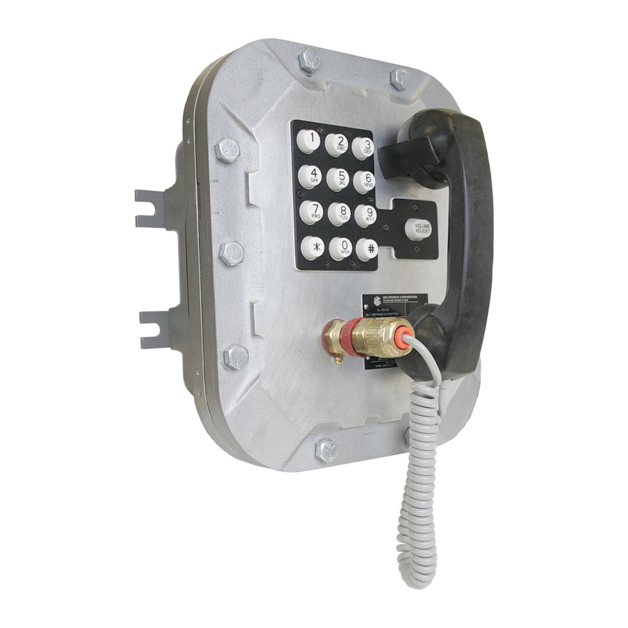
Model 352-701 and 352-703
Division 1
Confidentiality Notice
This manual is provided solely as an operational, installation, and maintenance guide and contains
sensitive business and technical information that is confidential and proprietary to GAI-Tronics. GAI-
Tronics retains all intellectual property and other rights in or to the information contained herein, and
such information may only be used in connection with the operation of your GAI-Tronics product or
system. This manual may not be disclosed in any form, in whole or in part, directly or indirectly, to any
third party.
General Information
GAI-Tronics' Class I, Division 1 VoIP Telephones are constructed of cast aluminum and are
weatherproof and corrosion resistant. User operation is identical to that of a standard analog telephone—
simply lift the handset and dial the desired telephone number.
GAI-Tronics' VoIP Telephones are designed for connection to a 10/100 BaseT Ethernet, and operate
from either Power-over-Ethernet or an external power source. The VoIP Telephones provide point-to-
point communications between personnel throughout a facility over an existing LAN.
This manual applies to the following models:
Model 352-701 Division 1 VoIP Telephone
Model 352-703 Division 1 VoIP Telephone with Headset
In addition to providing standard telephone operation, the VoIP
telephones feature real-time alarm reporting enabling system
supervisors to monitor the telephones' activity and address
caller needs or maintenance issues immediately. Also, four
user-configurable inputs and two outputs have been provided
for peripheral control.
System Requirements and Limitations
GAI-Tronics VoIP Telephones require Power-over-Ethernet or
a local 48 V dc power source for operation. Two VoIP
telephones can be connected in a peer-to-peer configuration
without the need for a LAN, however, a 10/100 BaseT Ethernet
with SIP server is required for systems containing three or more
VoIP Telephones. Conferences are limited by the customer's
LAN media capabilities and the services available at each end
point.
GAI-Tronics Corporation 400 E. Wyomissing Ave. Mohnton, PA 19540 USA
V
ISIT WWW
G A I - T R O N I C S ® C O R P O R A T I O N
A H U B B E L L C O M P A N Y
VoIP Telephones
610-777-1374 800-492-1212 Fax: 610-796-5954
.
-
.
GAI
TRONICS
COM FOR PRODUCT LITERATURE AND MANUALS
Pub. 42004-456B
Figure 1. Model 352-701 Division 1
VoIP Telephone
Advertisement
Table of Contents

Related Manuals for GAI-Tronics 352-701


Summary of Contents for GAI-Tronics 352-701
-
Page 1: General Information
Tronics retains all intellectual property and other rights in or to the information contained herein, and such information may only be used in connection with the operation of your GAI-Tronics product or system. This manual may not be disclosed in any form, in whole or in part, directly or indirectly, to any third party. -
Page 2: Tips For Voip Subscribers
Pub. 42004-456B Model 352-701 and 352-703 Division 1 VoIP Telephones Page 2 of 20 Tips for VoIP Subscribers If you have or are thinking of subscribing to an interconnected VoIP service, you should: Provide your accurate physical address to your interconnected VoIP service provider to ensure that emergency services can quickly be dispatched to your location. - Page 3 30 ft-lbs. Make certain no cover bolts are omitted. Use only those bolts supplied with the enclosure. When installing any GAI-Tronics telephone equipment, please adhere to the following guidelines to ensure the safety of all personnel: ...
-
Page 4: Cable Entries
Pub. 42004-456B Model 352-701 and 352-703 Division 1 VoIP Telephones Page 4 of 20 Mounting : The mounting surface must be able to support the weight of the telephone, which is 28 lbs. The enclosure must be securely fastened with 3/8-inch diameter steel mounting bolts located on all four mounting feet. -
Page 5: Hardware Description
Hardware Description External Model 352-701 contains a handset with an approved cable gland, standard keypad, volume control button, and applicable approval labeling. The handset rests on a cradle, which has a magnetic reed switch to signal an off-hook condition. The enclosure is sealed with ten cover mounting bolts located around the perimeter of the enclosure’s flange. - Page 6 Pub. 42004-456B Model 352-701 and 352-703 Division 1 VoIP Telephones Page 6 of 20 For the Model 352-703 Division 1 VoIP Telephone with the headset option, the cradle and handset are replaced with a removable headset and headset activation bracket.
- Page 7 Pub. 42004-456B Model 352-701 and 352-703 Division 1 VoIP Telephones Page 7 of 20 Internal All standard components are mounted to the rear of the front cover. See Figure 6 for the parts layout. Figure 6. Model 352-70x Division 1 VoIP Telephone - Internal View e:\standard ioms - current release\42004 instr.
- Page 8 Pub. 42004-456B Model 352-701 and 352-703 Division 1 VoIP Telephones Page 8 of 20 Wiring WARNING The front cover is not hinged to the rear enclosure. When the cover bolts are removed, the cover must be adequately supported. 1. While supporting the front cover, remove the ten cover bolts on the enclosure flange. Pull the front cover far enough away to expose the internal connections.
- Page 9 Pub. 42004-456B Model 352-701 and 352-703 Division 1 VoIP Telephones Page 9 of 20 Figure 8. Input Cable Connections at P12 Figure 9. Output Cable Connections at P10 Figure 10. Power Power-Over-Ethernet (POE) Connect power to the system as indicated in your POE equipment manual. (Power Mode A, Class 0) Local Power When POE is not available, this telephone can operate from a local 48 V dc power source.
-
Page 10: Pin Label
On, Off, Pulse, Mute, Ring, Call, Connect, Hook, In Use, Ring Cadence, Ring Out, Page, Registered, or Emergency. In some modes, the duration of the activation or on/off times can also be set. Refer to the “Logic Settings” section of GAI-Tronics Pub. 42004-481, “VoIP Telephone Configuration Guide” for more details. -
Page 11: Status Indication
Pub. 42004-456B Model 352-701 and 352-703 Division 1 VoIP Telephones Page 11 of 20 Table 3. Recommended Cabling Cable Use Size Cat5 or Cat5e UTP cable with an RJ45 connector Power Two-conductor, No. 22 AWG is typical Inputs Two-conductor, No. 22 AWG is typical Output contacts Two or three-conductor, No. -
Page 12: External Controls
Pub. 42004-456B Model 352-701 and 352-703 Division 1 VoIP Telephones Page 12 of 20 Attach the Front Cover After all adjustments have been completed, inspect and clean the machined flange joint surfaces of both the cover and box. Surfaces must be smooth, free of nicks, scratches dirt or any foreign particle build-up that would prevent a proper seal. -
Page 13: Quick Start Guide
Pub. 42004-456B Model 352-701 and 352-703 Division 1 VoIP Telephones Page 13 of 20 Programming Refer to Pub. 42004-396, VoIP Telephone Configuration Guide for detailed programming and configuration instructions. Quick Start Guide For easier set up, configure the software prior to installing the telephone in a hazardous environment. The... -
Page 14: Alternative Configuration Methods
Pub. 42004-456B Model 352-701 and 352-703 Division 1 VoIP Telephones Page 14 of 20 A CD containing all help files and the configuration file tool is available from GAI-Tronics on request. Figure 12. Alternative Configuration Methods There are three methods for configuring GAI-Tronics Handset VoIP telephones: ... -
Page 15: Operation
Pub. 42004-456B Model 352-701 and 352-703 Division 1 VoIP Telephones Page 15 of 20 Operation Model 352-701 Handset Operation 1. Lift the handset to place a call. 2. The handset receiver volume control located on the front cover keypad, can be adjusted to the desired level by pressing the volume control push button. - Page 16 Pub. 42004-456B Model 352-701 and 352-703 Division 1 VoIP Telephones Page 16 of 20 Model 352-703 Headset Operation 1. To connect the headset, plug it into the flexible plug on the front of the telephone by removing the sealing cap from the receptacle, aligning the connector pins, and screwing the two ends together. See Figure 14.
-
Page 17: Maintenance
If your telephone requires depot service, contact your Regional Service Center for a return authorization number (RA#). Equipment should be shipped prepaid to GAI-Tronics with a return authorization number and a purchase order number. If the equipment is under warranty, repairs will be made without charge. -
Page 18: Troubleshooting
Pub. 42004-456B Model 352-701 and 352-703 Division 1 VoIP Telephones Page 18 of 20 Troubleshooting Table 4. Troubleshooting Chart Problem Possible Solution Low volume in handset Increase the volume setting using the Volume Adjust button on the front or headset panel. -
Page 19: Specifications
Pub. 42004-456B Model 352-701 and 352-703 Division 1 VoIP Telephones Page 19 of 20 Specifications Power ....... Power-over-Ethernet, 802.3af compliant (via RJ45) Power Mode A, Class 0, or External power supply: 48 V dc, 200 mA A separate, isolated supply must be provided for each telephone. - Page 20 Pub. 42004-456B Model 352-701 and 352-703 Division 1 VoIP Telephones Page 20 of 20 Environmental Operating temperature ................−4º F to +140º F (−20º C to +60º C) Humidity ........................95% non-condensing Mechanical Enclosure ................Cast aluminum with aluminized lacquer paint Handset Cord ............
-
Page 21: Warranty
Warranty Equipment. GAI-Tronics warrants for a period of one (1) year from the date of shipment, that any GAI-Tronics equipment supplied hereunder shall be free of defects in material and workmanship, shall comply with the then-current product specifications and product literature, and if applicable, shall be fit for the purpose specified in the agreed-upon quotation or proposal document.
Need help?
Do you have a question about the 352-701 and is the answer not in the manual?
Questions and answers