Table of Contents
Advertisement
Quick Links
Retrofit VoIP Telephones
Confidentiality Notice .....................................................................................................................3
Product Overview ............................................................................................................................3
Features and Functions .......................................................................................................................... 3
System Requirements and Limitations ................................................................................................. 5
VoIP Subscriber Tips ............................................................................................................................. 6
Operation .........................................................................................................................................6
Autodial Emergency Calls (All Models) ................................................................................................ 6
Keypad Calls (Models 398-712CB, 398-712RT, and 398-712TP) ....................................................... 6
Receive a Call .......................................................................................................................................... 6
Multicast Broadcast ................................................................................................................................ 7
Monitoring and Reporting ..................................................................................................................... 7
Status Indication ..................................................................................................................................... 7
Power .................................................................................................................................................... 7
Heartbeat ............................................................................................................................................... 7
Link ....................................................................................................................................................... 7
Speed ..................................................................................................................................................... 7
VoIP Circuit PCBA Pushbuttons .......................................................................................................... 8
Reset ...................................................................................................................................................... 8
Factory .................................................................................................................................................. 8
Installation ......................................................................................................................................8
General Information ............................................................................................................................... 8
Safety Guidelines .................................................................................................................................. 8
Station Placement .................................................................................................................................. 9
Security Hardware ................................................................................................................................ 9
Telephone Removal and Replacement (All Models) ............................................................................ 9
Field Wiring ........................................................................................................................................... 14
Recommended Cabling ....................................................................................................................... 15
Power .................................................................................................................................................. 16
Network Cable .................................................................................................................................... 16
Auxiliary I/O ....................................................................................................................................... 16
USB port ................................................................................................................................................ 17
Strobe Connection ................................................................................................................................. 17
GAI-TRONICS 3030 KUTZTOWN RD. READING, PA 19605 USA
610-777-1374 ◼ 800-492-1212 ◼ Fax: 610-796-5954
V
ISIT WWW
G A I - T R O N I C S
A H U B B E L L C O M P A N Y
T
A B L E O F
.
-
.
GAI
TRONICS
COM FOR PRODUCT LITERATURE AND MANUALS
®
C
O N T E N T S
Pub. 42004-543A
Advertisement
Table of Contents

Related Manuals for GAI-Tronics RED ALERT 397-710CB


Summary of Contents for GAI-Tronics RED ALERT 397-710CB
-
Page 1: Table Of Contents
Power ..............................16 Network Cable ............................ 16 Auxiliary I/O ............................16 USB port ..............................17 Strobe Connection ..........................17 GAI-TRONICS 3030 KUTZTOWN RD. READING, PA 19605 USA 610-777-1374 ◼ 800-492-1212 ◼ Fax: 610-796-5954 ISIT WWW TRONICS COM FOR PRODUCT LITERATURE AND MANUALS... - Page 2 Service and Spare Parts ........................20 Reference Documentation ......................21 Specifications ..........................21 Electrical ..............................21 Mechanical ............................. 22 Approvals ............................23 GAI-TRONICS 3030 KUTZTOWN RD. READING, PA 19605 USA 610-777-1374 ◼ 800-492-1212 ◼ Fax: 610-796-5954 ISIT WWW TRONICS COM FOR PRODUCT LITERATURE AND MANUALS...
-
Page 3: Confidentiality Notice
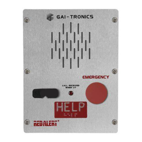
GAI-Tronics product or system. This manual may not be disclosed in any form, in whole or in part, directly or indirectly, to any third party. - Page 4 Pub. 42004-543A Retrofit VoIP Telephones Page 4 of 21 Table 1. Model Chart Model Description 397-710CB Code Blue Flush-Mount Hands-free VoIP Telephone, weatherproof brushed stainless-steel front panel, HELP autodial push button, and C ECEIVED LED. 397-710TP Talk-A-Phone Flush-Mount Hands-free VoIP Telephone, weatherproof brushed stainless-steel front panel, HELP autodial push button, and C ECEIVED LED.
-
Page 5: System Requirements And Limitations
Pub. 42004-543A Retrofit VoIP Telephones Page 5 of 21 Figure 3. Model 397-710TP Figure 4. Model 398-712CB Figure 5. Model 398-712RT Figure 6. Model 398-712TP System Requirements and Limitations RED ALERT VoIP Telephones require PoE (Power-over-Ethernet) or a local 24 to 48-volt dc power source for operation. -
Page 6: Voip Subscriber Tips
Pub. 42004-543A Retrofit VoIP Telephones Page 6 of 21 VoIP Subscriber Tips New and existing subscriptions to an interconnected VoIP service provider should address the following points: • Provide accurate physical address information to the VoIP service provider to ensure that emergency services can quickly be dispatched to the location. -
Page 7: Multicast Broadcast
When making a multicast call, the SIP server sends the page request to a specific IP address and multiple telephones accept and play the subsequent audio. GAI-Tronics’ VoIP telephones can be programmed for up to eight multicast addresses to permit the receipt of multicast broadcasts from different sources or to enable zoning of broadcasts. -
Page 8: Voip Circuit Pcba Pushbuttons
Class 2 circuit wiring must be performed in accordance with the NEC. Safety Guidelines When installing any GAI-Tronics equipment, please adhere to the following guidelines to ensure the safety of all personnel: •... -
Page 9: Station Placement
The telephones described in this manual are vandal resistant. The front panel of each telephone is attached to its enclosure with security screws. A GAI-Tronics Model 233-001 Security Screwdriver or Torx T-25 security head tip (sold separately) is required for installing the telephone. - Page 10 Pub. 42004-543A Retrofit VoIP Telephones Page 10 of 21 Figure 7. Back Box for Ramtel (RT) and Code Blue (CB) P:\Standard IOMs - Current Release\42004 Instr. Manuals\42004-543A.docx 03/20...
- Page 11 Pub. 42004-543A Retrofit VoIP Telephones Page 11 of 21 Figure 8. Cutout for Ramtel (RT) Telephones P:\Standard IOMs - Current Release\42004 Instr. Manuals\42004-543A.docx 03/20...
- Page 12 Pub. 42004-543A Retrofit VoIP Telephones Page 12 of 21 Figure 9. Cutout for Code Blue (CB) Telephones P:\Standard IOMs - Current Release\42004 Instr. Manuals\42004-543A.docx 03/20...
- Page 13 Pub. 42004-543A Retrofit VoIP Telephones Page 13 of 21 Figure 10. Back Box for Talk-A-Phone (TP) P:\Standard IOMs - Current Release\42004 Instr. Manuals\42004-543A.docx 03/20...
-
Page 14: Field Wiring
Pub. 42004-543A Retrofit VoIP Telephones Page 14 of 21 Figure 11. Cutout for Talk-A-Phone (TP) Telephones Field Wiring Pull the required field cables into the rear enclosure and install the connections as indicated in the following subsections (see Table 2 for recommended conductor sizes and Figure 12 for wiring details). : Consult the National Electrical Code (NFPA 70), Canadian Standards Association (CSA 22.1), and local codes for the specific requirements regarding your installation. -
Page 15: Recommended Cabling
Pub. 42004-543A Retrofit VoIP Telephones Page 15 of 21 Recommended Cabling Table 2. Recommended Cabling Cable Use Size Cat5 or Cat5e UTP cable with an RJ45 connector Power Two-conductor, No. 22 AWG is typical Inputs Two-conductor, No. 22 AWG is typical Output contacts Two or three-conductor, No. -
Page 16: Power
Pub. 42004-543A Retrofit VoIP Telephones Page 16 of 21 Power Ground The enclosure must be connected to earth ground. 1. Install a #6 ring lug on the ground conductor. 2. Secure it to the ground terminal, located on the rear of the front panel. Power-Over-Ethernet (PoE) Connect power to the system as indicated in the PoE equipment manual. -
Page 17: Usb Port
The relay can remain energized for the duration of the emergency call. An output is often used to operate a GAI-Tronics Model 540-001 or 541-001 Strobe (sold separately) (see Figure 13). Refer to the appropriate installation instructions included with the strobe for additional information. -
Page 18: Programming
Pub. 42004-543A Retrofit VoIP Telephones Page 18 of 21 Figure 13. GAI-Tronics Models 540-001 and 541-001 Strobe Connection Detail Programming The network configuration must provide VoIP service (using the SIP protocol) between the desired locations before attempting to configure a GAI-Tronics VoIP telephone. -
Page 19: Voip Pcba Initial Network Configuration
Pub. 42004-543A Retrofit VoIP Telephones Page 19 of 21 VoIP PCBA Initial Network Configuration Configure each VoIP PCBA for operation on the network prior to installation. Assign a local ID, domain, proxy, and registrar. 1. Assign a host name. Host names provide identification of different VoIP PCBAs on the network. 2. -
Page 20: Cleaning
Contact a regional service center for an RA# (return authorization number) if the telephone requires service. Ship equipment prepaid to GAI-Tronics with an RA# and a purchase order number. Repairs or a replacement will be made in accordance with GAI-Tronics’ warranty policy if the equipment is under warranty. -
Page 21: Reference Documentation
Pub. 42004-543A Retrofit VoIP Telephones Page 21 of 21 Table 7. Replacement and Optional Parts Part No. Description 233-001 Model 233-001 Security Screwdriver 12565-712 VoIP Circuit PCBA Replacement Kit 12542-002 Security Screws (Torx T-25), ½-inch, Pack of 15 12520-009 Push Button Replacement Kit (Emergency) 12521-004 Microphone Replacement Kit 12522-007... -
Page 22: Mechanical
Pub. 42004-543A Retrofit VoIP Telephones Page 22 of 21 Outputs Output 1 ..................... 8 A @ 30 V ac/dc (resistive load) Output 2 ..................... 8 A @ 30 V ac/dc (resistive load) Indicators External ........................off-hook indicator light Internal on VoIP PCBA ..............heartbeat, link, power, and speed LEDs Audio output ................. -
Page 23: Approvals
Pub. 42004-543A Retrofit VoIP Telephones Page 23 of 21 Model 398-712CB Panel ....................11.75 H × 8.50 W in (298.4 × 215.9 mm) Back box (depth from mounting surface) ................2.56 in (65.0 mm) Weight ............................7.0 lb (3.2 kg) Approvals Compliance to Standard .................... - Page 24 If the services fail to meet the applicable industry standard, GAI-Tronics will re- perform such services at no cost to buyer to correct said deficiency to Company's satisfaction provided any and all issues are identified prior to the demobilization of the Contractor's personnel from the work site.
Need help?
Do you have a question about the RED ALERT 397-710CB and is the answer not in the manual?
Questions and answers