
Related Manuals for Edgewater Networks EdgeConnect 800PoE


Summary of Contents for Edgewater Networks EdgeConnect 800PoE
-
Page 1: Ethernet Switch
EdgeConnect 800PoE Managed Power over Ethernet Switch Installation Guide 300-800PoE-001... - Page 2 The information in this guide may be changed without notice. The manufacturer assumes no responsibility for any errors which may appear in this guide. Ethernet is a trademark of XEROX Corporation. Microsoft, Windows and Windows logo are trademarks of Microsoft Corporation. Copyright 2006.
- Page 3 Contents INTRODUCTION 1 1.1 P ACKAGE ONTENTS 1.2 H OW TO SE THIS UIDE INSTALLATION 1 2.1 8- 100B TX + 2- 1000B T / M GBIC P E PSE P PORTS PORTS RODUCT ESCRIPTION VERVIEW 2.2 8- 100B + 2- P 1000B T / M GBIC P...
-
Page 4: Table Of Contents
Contents 3.2.12 The Admin of the switch SPECIFICATIONS 4.1 C ABLE PECIFICATIONS 4.2 T ECHNICAL PECIFICATIONS 4.2.1 Software Specification 4.2.2 Hardware Specification 4.2.3 LED Display 4.3 E NVIRONMENTS OFTWARE PECIFICATION 4.4 S TANDARD ONFORMANCE WARRANTY STATEMENT 109... -
Page 5: Introduction
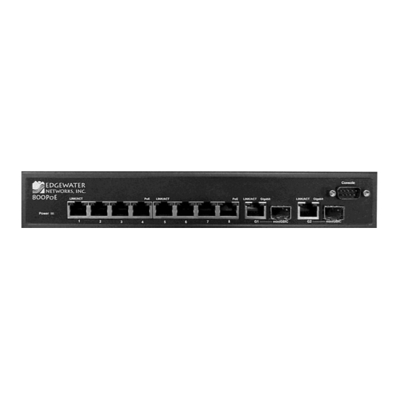
800PoE Managed Power Over Ethernet Switch User Guide 1 Introduction 800PoE is a 8 ports PoE Layer 2 management switch, it supports up to 8 ports PoE Power source (PSE) to supply PoE power for the connected Power Device (PD). Throughout this guide, 8-Ports 100BaseTx +2-ports 1000 BaseT / Mini GBIC PoE PSE Layer2 Management Switch will be referred to PoE PSE Switch. -
Page 6: Ports 100Basetx + 2-Ports1000Baset / Mini Gbic Poe Pse Product Description Overview
800PoE Managed Power Over Ethernet Switch User Guide how to install it on the desktop or shelf. Basic knowledge of networking is assumed. Read this chapter completely before continuing. 2.1 8-ports 100BaseTX + 2-ports1000BaseT / Mini GBIC PoE PSE Product Description Overview 800PoE is the PoE PSE model to offer 100W power buget for whole with built-in power management function, these PoE L2 management switch can adjust the supplied power dynamically to save the power for wide application range. - Page 7 800PoE Managed Power Over Ethernet Switch User Guide additional PDs cannot be connected .When this value is exceeded, ports will be deactivated, according to user-defined priorities. The power budget is managed according to the following user-definable parameters: maximum available power, ports priority, maximum allowable power per port.
-
Page 8: Installing The 8-Ports 100Basetx + 2-Ports 1000Baset/ Minigbic Poe Pse Layer
800PoE Managed Power Over Ethernet Switch User Guide Orange. Lights to indicate a device is connected utilizing Power over Ethernet on the corresponding port (1 through 8). Gigabit Orange, Lights to indicate a Gigabit connection on the corresponding RJ-45 port (G1 through G2). Ports The Fast Ethernet ports support network speeds of 10Mbps or 100Mbps. -
Page 9: Pre-Installation Considerations
800PoE Managed Power Over Ethernet Switch User Guide 2.4.1 Pre-Installation Considerations Gigabit Considerations: If you will be using the switch for Gigabit applications, keep in mind that the maximum UTP cabling length using Category 5e cable is 328 feet (100 meters). Positioning the switch: When choosing a location for the switch, observe the following guidelines: Keep enough ventilation space between the switch and the surrounding objects. -
Page 10: Configuration
800PoE Managed Power Over Ethernet Switch User Guide 3 Configuration The configuration programs are supplied with 8-ports 100BaseTX +2 min GBIC Layer 2 Management or 8-ports 100BaseTX +2 min GBIC PoE PSE Layer 2 Management Switch. Unlike the unmanaged switch (dumb switch), the switch performs "management" functions that make the switch operate more effectively. -
Page 11: Connecting A Pc Or Terminal To The Rs-232 Port
800PoE Managed Power Over Ethernet Switch User Guide interface. Read the following sections to start up! 3.1.1 Connecting a PC or Terminal to the RS-232 Port When you are ready to configure the Management Function of the switch, make sure you have connected the supplied RS-232 serial cable to the RS-232 port at the front panel of your switch and your PC. -
Page 12: How To Set Up The Switch
800PoE Managed Power Over Ethernet Switch User Guide Figure 3-1 Password Information Window 1. In the Password field, enter the factory default password “” (or enter a user-defined password if you changed the factory default password). 2. Click the Login button. The Basic Setup/General parameters in Figure 3-2 appear. 3.2.2 How to set up the switch The summary screen provides Device and System Information about the Switch. - Page 13 800PoE Managed Power Over Ethernet Switch User Guide The Basic Setup Table include the Network Settings (see figure 3-3), which allows you to assign DHCP or static IP settings to interfaces and assign default gateways. In the Networking Setting screen, you can set these parts as below: Identification: a) System Name, type your system name.
- Page 14 800PoE Managed Power Over Ethernet Switch User Guide In the Basic Setup Table, you can see the Time Setup (see figure 3-4), by which you can configure the time settings for the Switch. You can choose Daylight Saving to enable it on the Switch.
-
Page 15: Port Configuration
800PoE Managed Power Over Ethernet Switch User Guide 3.2.3 Port Configuration In this field, you can see these parts, such as port settings, Link aggregation, LACP and PoE power settings (only when the device with PoE Function) 3.2.3.1 Port settings To use the port settings screen for setting up each of the switch’s ports. - Page 16 800PoE Managed Power Over Ethernet Switch User Guide Speed, shows the connection speed of the port and the speed can be configured only when auto-negotiation is disabled on that port. Duplex, the port duplex mode, Full (transmission occurs in both directions simultaneously) or Half (transmission occurs in only one direction at a time).
- Page 17 800PoE Managed Power Over Ethernet Switch User Guide Port Configuration Detail screen (see figure 3-6) Port, indicates the number of the port. Description, where can be entered by clicking on the Detail button. Port Type, this is the port type. Admin Status, the port can be taken offline by selecting the Down option.
- Page 18 800PoE Managed Power Over Ethernet Switch User Guide a) Max Capability, which indicates that the port speeds and duplex mode settings can be accepted. b) 10 Half, indicates that the port is advertising a 10Mbps half duplex mode setting. c) 10 Full, indicates that the port is advertising a 10Mbps full duplex mode setting. d)100 Half, indicates that the port is advertising a 100Mbps half duplex mode setting.
- Page 19 800PoE Managed Power Over Ethernet Switch User Guide 3.2.3.2 Link Aggregation When you enter the Link Aggregation, you can see these parts (see figure 3-7), such as: LAG, shows whether the port is part of a LAG. Description, indicates the description of the ports. Administrative Status, up indicates that the port is available and down shows administrator has taken the port offline.
- Page 20 800PoE Managed Power Over Ethernet Switch User Guide 3.2.3.3 LACP Aggregated Links can be manually setup or automatically established on the relevant links by enabling Link Aggregation Control Protocol (LACP). Aggregate ports can be linked into link-aggregation port-groups. Each group is comprised of ports with the same speed, set to full-duplex operation.
- Page 21 800PoE Managed Power Over Ethernet Switch User Guide Figure 3-8 If the product is with PoE Function (the switch with PoE Function), then you will see the forth table named PoE power settings. 3.2.3.4 PoE Power Settings The PoE power settings include these items, such as port, admin status, priority, power allocation, power consumption (see figure 3-9) Port, shows the port number you select.
-
Page 22: The Vlan Configuration
800PoE Managed Power Over Ethernet Switch User Guide Figure 3-9 3.2.4 The VLAN Configuration In this field, there are five items, such as Create VLAN, Port setting, Ports to VLAN, VLAN to Ports, GVRP… 3.2.4.1 Create VLAN In this table, the information and global parameters for configuring and working with VLAN s will be provided (see figure 3-10). - Page 23 800PoE Managed Power Over Ethernet Switch User Guide Figure 3-10 3.2.4.2 Port setting In this port setting screen (refer to figure 3-11), the parameters managing ports that are part of a VLAN will be provided, and you can set the default VLAN ID (PVID). All untagged packets arriving to the device are tagged by the ports PVID.
- Page 24 800PoE Managed Power Over Ethernet Switch User Guide Admit Tag Only, indicates that only tagged packets are accepted on the port. Admit All, indicates that both tagged and untagged packets are accepted on the port. PVID, assigns a VLAN ID to untagged packets. The possible values are 2 to 4094. VLAN 4095 is defined as per standard and industry practice as the discard VLAN.
- Page 25 800PoE Managed Power Over Ethernet Switch User Guide selecting and configuring the presented configuration options, you can refer to figure 3-12. VLAN, where means the VLAN number. Access, indicates the port belongs to a single untagged VLAN. When a port is in Access mode, the packet types which are accepted on the port cannot be designated.
- Page 26 800PoE Managed Power Over Ethernet Switch User Guide 3.2.4.4 VLAN to Ports The VLAN to Ports screen (see figure 3-13) contains fields for configuring VLANs to a port. This screen displays these parts, such as: Interface, displays the interface number. Mode, by which indicates the port to VLAN mode.
- Page 27 800PoE Managed Power Over Ethernet Switch User Guide cannot be configured to a VLAN. The LAG to which belongs can be configured to a VLAN. Figure 3-13 3.2.4.5 GVRP GARP VLAN Registration Protocol (GVRP) is specifically provided for automatic distribution of VLAN membership information among VLAN-aware bridges. GVRP allows VLAN-aware bridges to automatically learn VLANs to bridge ports mapping, without having to individually configure each bridge and register VLAN membership.
-
Page 28: The Statistic Of The Switch
800PoE Managed Power Over Ethernet Switch User Guide GVRP State, when the checkbox is checked, GVRP is enabled on the interface. Dynamic VLAN Creation, when the checkbox is checked, Dynamic VLAN creation is enabled on the interface. GVRP Registration, when the checkbox is checked, VLAN registration through GVRP is enabled on the device, the Update button adds the configured GVRP setting to the table at the bottom of the screen. - Page 29 800PoE Managed Power Over Ethernet Switch User Guide Refresh Rate, which defines the amount of time that passes before the interface statistics are refreshed. The possible field values are: a) No Refresh, indicates that the RMON statistics are not refreshed. b) 15 Sec, which indicates that the RMON statistics are refreshed every 15 seconds.
- Page 30 800PoE Managed Power Over Ethernet Switch User Guide Jabbers, indicates the total number of received packets that were longer than 1518 octets. This number excludes frame bits, but includes FCS octets that had either a bad Frame Check Sequence (FCS) with an integral number of octets (FCS Error) or a bad FCS with a non-integral octet (Alignment Error) number.
- Page 31 800PoE Managed Power Over Ethernet Switch User Guide The RMON History Control screen is divided into RMON History and Log Table. Log Table includes the following parts (see figure 3-16) Source Interface, displays the interface from which the history samples were taken. The possible field values are: a) Port, specifies the port from which the RMON information was taken.
- Page 32 800PoE Managed Power Over Ethernet Switch User Guide RMON History The RMON History screen (see figure 3-17) contains interface specific statistical network samplings. Each table entry represents all counter values compiled during a single sample. Sample No, which indicates the sample number from which the statistics were taken. Received Bytes (Octets), displays the number of octets received on the interface since the device was last refreshed.
- Page 33 800PoE Managed Power Over Ethernet Switch User Guide Multicast Packets, displays the number of good Multicast packets received on the interface since the device was last refreshed. CRC Align Errors, which displays the number of CRC and Align errors that have occurred on the interface since the device was last refreshed.
- Page 34 800PoE Managed Power Over Ethernet Switch User Guide 3.2.5.3 RMON Alarm The RMON Alarm screen (see figure 3-18) contains fields for setting network alarms. Network alarms occur when a network problem, or event, is detected. Rising and falling thresholds generate events. Alarm Entry, indicates a specific alarm.
- Page 35 800PoE Managed Power Over Ethernet Switch User Guide Rising Threshold, displays the rising counter value that triggers the rising threshold alarm. The rising threshold is presented on top of the graph bars. Each monitored variable is designated a color. Rising Event, displays the mechanism in which the alarms are reported. The possible field values are: a) LOG.
- Page 36 800PoE Managed Power Over Ethernet Switch User Guide 3.2.5.4 RMON Events The RMON Events screen (see figure 3-19) contains fields for defining RMON events. Add Event: Event Entry, displays the event. Community, where displays the community to which the event belongs. Description, displays the user-defined event description.
- Page 37 800PoE Managed Power Over Ethernet Switch User Guide Time, where displays the time that the event occurred. Figure 3-19 Figure 3-20...
- Page 38 800PoE Managed Power Over Ethernet Switch User Guide 3.2.5.5 Port Utilization The Port Utilization screen (see figure 3-21) indicates the amount of resources each interface is currently consuming. Ports in green are functioning normally, while ports in red are currently transmitting an excessive amount of network traffic. Refresh Rate, indicates the amount of time that passes before the port utilization statistics are refreshed.
- Page 39 800PoE Managed Power Over Ethernet Switch User Guide 60 Sec, which indicates that the EAP statistics are refreshed every 60 seconds. Name, that displays the measured 802.1x statistic. Description, describes the measured 802.1x statistic. Packet, displays the amount of packets measured for the particular 802.1x statistic. Figure 3-22 3.2.5.7 GVRP...
- Page 40 800PoE Managed Power Over Ethernet Switch User Guide refreshed. The possible field values are: No Refresh, indicates that the GVRP statistics are not refreshed. 15 Sec, which indicates that the GVRP statistics are refreshed every 15 seconds. 30 Sec, which indicates that the GVRP statistics are refreshed every 30 seconds. 60 Sec, which indicates that the GVRP statistics are refreshed every 60 seconds.
-
Page 41: The Acl Of The Switch
800PoE Managed Power Over Ethernet Switch User Guide 3.2.6 The ACL of the switch 3.2.6.1 IP Based ACL The IP Based ACL (Access Control List) screen (see figure 3-24) contains information for defining IP Based ACLs. ACL Name, displays the user-defined IP based ACLs. New ACL Name, defines a new user-defined IP based ACL. - Page 42 800PoE Managed Power Over Ethernet Switch User Guide Select from List, where selects from a protocols list on which ACE can be based. The possible field values are: a) Any, matches the protocol to any protocol. b) EIGRP, which indicates that the Enhanced Interior Gateway Routing Protocol (EIGRP) is used to classify network flows.
- Page 43 800PoE Managed Power Over Ethernet Switch User Guide drop-down menu. The possible field range is 0 - 65535. Destination Port, where defines the TCP/UDP destination port. This field is active only if 800/6-TCP or 800/17-UDP is selected in the Select from List drop-down menu. The possible field range is 0 - 65535.
- Page 44 800PoE Managed Power Over Ethernet Switch User Guide 3.2.6.2 MAC Based ACL The MAC Based ACL screen (see figure 3-25) allows a MAC based ACL to be defined. ACEs can be added only if the ACL is not bound to an interface. ACL Name, displays the user-defined MAC based ACLs.
-
Page 45: The Security Of The Switch
800PoE Managed Power Over Ethernet Switch User Guide 255.36.184.00, the first eight bits of the IP address are ignored, while the last eight bits are used. Dest. MAC Address, where matches the destination MAC address to which packets are addressed to the ACE. Wildcard Mask, which defines the destination IP address wildcard mask. - Page 46 800PoE Managed Power Over Ethernet Switch User Guide rule, which is Drop unmatched packets. You can refer to figure 3-26. Interface, indicates the interface to which the ACL is bound. ACL Name, indicates the ACL which is bound to the interface. Use the Add to List button to add the ACL Binding configuration to the ACL Binding Table at the bottom of the screen.
- Page 47 800PoE Managed Power Over Ethernet Switch User Guide Number of Retries, defines the number of transmitted requests sent to RADIUS server before a failure occurs. The possible field values are 1 - 10. Three is the default value. Timeout for Reply, which defines the amount of the time in seconds the device waits for an answer from the RADIUS server before retrying the query, or switching to the next server.
- Page 48 800PoE Managed Power Over Ethernet Switch User Guide 3.2.7.3 TACACS+ The device provides Terminal Access Controller Access Control System (TACACS+) client support. TACACS+ provides centralized security for validation of users accessing the device. TACACS+ provides a centralized user management system, while still retaining consistency with RADIUS and other authentication processes.
- Page 49 800PoE Managed Power Over Ethernet Switch User Guide The Timeout for Reply, which displays the amount of time that passes before the connection between the device and the TACACS+ server times out. The field range is 1-30 seconds. Status, displays the connection status between the device and the TACACS+ server. The possible field values are: Connected, there is currently a connection between the device and the TACACS+ server.
- Page 50 800PoE Managed Power Over Ethernet Switch User Guide Port based authentication enables authenticating system users on a per-port basis via an external server. Only authenticated and approved system users can transmit and receive data. Ports are authenticated via the RADIUS server using the Extensible Authentication Protocol (EAP).
- Page 51 800PoE Managed Power Over Ethernet Switch User Guide d.2) Setting Timer On this screen, it includes port, re-authentication, resending EAP …. (refer to figure 3-30) Quiet Period, specifies the number of seconds that the switch remains in the quiet state following a failed authentication exchange (Range: 0-65535).
- Page 52 800PoE Managed Power Over Ethernet Switch User Guide 3.2.7.5 Port Security Work security screen (see figure 3-31) can be increased by limiting access on a specific port only to users with specific MAC addresses. MAC addresses can be dynamically learned or statically configured. Locked port security monitors both received and learned packets that are received on specific ports.
- Page 53 800PoE Managed Power Over Ethernet Switch User Guide Max Entries. Specifies the number of MAC addresses that can be learned on the port. The Max Entries field is enabled only if Locked is selected in the Interface Status field. In addition, the Limited Dynamic Lock mode is selected.
- Page 54 800PoE Managed Power Over Ethernet Switch User Guide 3.2.7.6 Multiple Hosts The Multiple Hosts screen (see figure 3-32) allows network managers to configure advanced port-based authentication settings for specific ports and VLANs. Port, displays the port number for which advanced port-based authentication is enabled. Enable Multiple Hosts.
- Page 55 800PoE Managed Power Over Ethernet Switch User Guide 3.2.7.7 Storm control The Storm Control included port, broadcast control, mode…. (see figure 3-33) Port, displays the port number for which storm control is enabled. Broadcast Control, which indicates whether broadcast packet types are forwarded on the specific interface.
-
Page 56: The Qos Of Switch
800PoE Managed Power Over Ethernet Switch User Guide Figure 3-33 3.2.8 The QoS of switch Network traffic is usually unpredictable, and the only basic assurance that can be offered is best effort traffic delivery. To overcome this challenge, Quality of Service (QoS) is applied throughout the network. - Page 57 800PoE Managed Power Over Ethernet Switch User Guide within the packet to determine the egress queue settings. The CoS Settings screen has two areas, CoS Settings and CoS to Queue. CoS Mode, which indicates if QoS is enabled on the interface. The possible values are: a) Disable, disables QoS on the interface.
- Page 58 800PoE Managed Power Over Ethernet Switch User Guide 3.2.8.2 Queue Setting The Queue Setting screen (see figure 3-35) contains fields for defining the QoS queue forwarding types. Queue, shows the queue for which the queue settings are displayed. The possible field range is 1 - 4.
- Page 59 800PoE Managed Power Over Ethernet Switch User Guide 3.2.8.3 DSCP Settings The DSCP Settings screen (see figure 3-36) enables mapping DSCP values to specific queues The DSCP Settings screen contains the following fields: DSCP, indicates the Differentiated Services Code Point value in the incoming packet. Queue, maps the DSCP value to the selected queue.
- Page 60 800PoE Managed Power Over Ethernet Switch User Guide 3.2.8.4 Bandwidth Screen The Bandwidth screen (refer to figure 3-37) allows network managers to define the bandwidth settings for a specified egress interface. Modifying queue scheduling affects the queue settings globally. The Bandwidth screen is not used with the Service mode, as bandwidth settings are based on services.
- Page 61 800PoE Managed Power Over Ethernet Switch User Guide 3.2.8.5 Basic Mode The Basic Mode screen (see figure 3-38) contains the following fields: Trust Mode, displays the trust mode. If a packet’s CoS tag and DSCP tag are mapped to different queues, the Trust Mode determines the queue to which the packet is assigned. Possible values are: CoS, which sets trust mode to CoS on the device and the CoS mapping determined the packet queue.
- Page 62 800PoE Managed Power Over Ethernet Switch User Guide 3.2.8.6 Advanced Mode Advanced QoS mode (see figure 3-39) provides rules for specifying flow classification and assigning rule actions that relate to bandwidth management. The rules are based on the Access Control Lists (see Access Control Tab) MAC ACLs and IP ACLs can be grouped together in more complex structures, called policies.
- Page 63 800PoE Managed Power Over Ethernet Switch User Guide DSCP In, which displays the DSCP In value. DSCP Out, which displays the current DSCP out value. A new value can be selected from the pull-down menu. Figure 3-40 The Policy Settings button opens the Policy Name screen (see figure 3-41): Policy Name, defines a new Policy name.
- Page 64 800PoE Managed Power Over Ethernet Switch User Guide Class Map, where selects an existing Class Map by name. New Class Map, by which the New Class Map button opens the New Class Map screen (see figure 3-42). Class Map Name, defines a new Class Map name Preferred ACL, which indicates if packets are first matched to an IP based ACL or a MAC based ACL, the possible field values are: a) IP Based ACLs, matches packets to IP based ACLs first, then matches packets to...
- Page 65 800PoE Managed Power Over Ethernet Switch User Guide b) Or, either the MAC-based or the IP-based ACL must match a packet. MAC ACL, matches packets to MAC based ACLs and to IP based ACLs. Figure 3-42 Aggregate Policer, where user-defined aggregate policers. The Aggregate Policer button opens the New Aggregate Policer screen.
-
Page 66: The Spanning Tree Of The Switch
800PoE Managed Power Over Ethernet Switch User Guide b) Remark DSCP, where remarks packet’s DSCP values exceeding the defined CIR value. c) None, forwarding packets exceeding the defined CIR value. Figure 3-43 3.2.9 The Spanning Tree of the switch Spanning Tree Protocol (STP) provides tree topography for any arrangement of bridges. STP also provides one path between end stations on a network, eliminating loops. - Page 67 800PoE Managed Power Over Ethernet Switch User Guide STP is based on the RSTP. In addition, Multiple STP transmits packets assigned to different VLANs through different MST regions. MST regions act as a single bridge. 3.2.9.1 STP Status The STP Status screen (see figure 3-44) describes the STP status on the device. Spanning Tree State, by which indicates if STP is enabled on the device.
- Page 68 800PoE Managed Power Over Ethernet Switch User Guide Forward Delay Time indicates the amount of time in seconds a bridge remains in a listening and learning state before forwarding packets. The default is 15 seconds. The range is 4 to 30 seconds. Topology Changes Counts, which indicates the total amount of STP state changes that have occurred.
- Page 69 800PoE Managed Power Over Ethernet Switch User Guide BPDU Handling, which determines how BPDU packets are managed when STP is disabled on the port/ device. BPDUs are used to transmit spanning tree information. The possible field values are: a) Filtering, where filters BPDU packets when spanning tree is disabled on an interface. This is the default value.
- Page 70 800PoE Managed Power Over Ethernet Switch User Guide 3.2.9.3 STP Port Settings Network administrators can assign STP settings to specific interfaces using the STP Interface Settings screen (see figure 3-46). The STP Interface Settings page contains the following fields: Interface, indicates the port or LAG on which STP is enabled. STP, which indicates if STP is enabled on the port.
- Page 71 800PoE Managed Power Over Ethernet Switch User Guide however it can learn new MAC addresses. Forwarding, the port that can forward traffic and learn new MAC addresses. Speed, where indicates the speed at which the port is operating. Path Cost, which indicates the port contribution to the root path cost. The path cost is adjusted to a higher or lower value, and is used to forward traffic when a path being rerouted.
- Page 72 800PoE Managed Power Over Ethernet Switch User Guide 3.2.9.4 RSTP Port settings While the classic spanning tree prevents Layer 2 forwarding loops in a general network topology, convergence can take between 30-60 seconds. This time may delay detecting possible loops, and propagating status topology changes. Rapid Spanning Tree Protocol (RSTP) detects and uses network topologies that allow a faster STP convergence without creating forwarding loops (refer to figure 3-47).
- Page 73 800PoE Managed Power Over Ethernet Switch User Guide Tree leaves. Backup ports occur only when two ports are connected in a loop by a point-to-point link. Backup ports also occur when a LAN has two or more connections connected to a shared segment. Disabled, which indicates the port is not participating in the Spanning Tree.
- Page 74 800PoE Managed Power Over Ethernet Switch User Guide migration test, press Activate next to the Activate Protocol Migration Test field. The test sends Link Control Protocol (LCP) packets to test if a data link is enabled. Figure 3-47 3.2.9.5 Spanning Tree Tab - MSTP Properties MSTP provides differing load balancing scenarios.
- Page 75 800PoE Managed Power Over Ethernet Switch User Guide the specified instance root. Figure 3-48 3.2.9.6 Spanning Tree Tab - MSTP Instance Settings MSTP opreation maps VLANs into STP instances (see figure 3-49) Packets assigned to various VLANs are transmitted along different paths within Multiple Spanning Trees Regions (MST Regions), Regions are one or more Multiple Spanning Tree bridges by which frames can be transmitted.
- Page 76 800PoE Managed Power Over Ethernet Switch User Guide Root Path Cost, which indicates the selected instance’s path cost. Bridge ID, indicates the bridge ID of the selected instance. Remaining Hops, which indicates the number of hops remaining to the next destination. Figure 3-49 3.2.9.7 Spanning Tree Tab - MSTP Interface Settings...
- Page 77 800PoE Managed Power Over Ethernet Switch User Guide a) Port. Specifies the port for which the MSTP settings are displayed. b) LAG. Specifies the LAG for which the MSTP settings are displayed. Port State, where indicates whether the port is enabled for the specific instance. Type, indicates if the port is a point-to-point port, or a port connected to a hub.
-
Page 78: The Multicast Of The Switch
800PoE Managed Power Over Ethernet Switch User Guide Designated Bridge ID, where indicates that the bridge ID number that connects the link or shared LAN to the root. Designated Port ID, by which indicates that the Port ID number on the designated bridge that connects the link or the shared LAN to the root. - Page 79 800PoE Managed Power Over Ethernet Switch User Guide 3.2.10.1 Multicast Tab - IGMP Snooping When IGMP Snooping (see figure 3-51) is enabled globally, all IGMP packets are forwarded to the CPU. The CPU analyzes the incoming packets and determines which ports want to join which Multicast groups, which ports have Multicast routers generating IGMP queries, which routing protocols are forwarding packets and Multicast traffic.
- Page 80 800PoE Managed Power Over Ethernet Switch User Guide Figure 3-51 3.2.10.2 Multicast Tab - Bridge Multicast The Bridge Multicast screen (see figure 3-52) displays the ports and LAGs attached to the Multicast service group in the Ports and LAGs tables. The Port and LAG tables also reflect the manner in which the port or LAGs joined the Multicast group.
- Page 81 800PoE Managed Power Over Ethernet Switch User Guide The configuration options are as follows: a) Static, indicates the port is user-defined. b) Dynamic, indicates the port is configured dynamically. c) Forbidden, forbidden ports are not included the Multicast group, even if IGMP snooping designated the port to join a Multicast group.
-
Page 82: The Snmp Of The Switch
800PoE Managed Power Over Ethernet Switch User Guide None, displays the port is not configured for Multicast service. Forbidden, forbidden ports are not included the Multicast group, even if IGMP snooping designated the port to join a Multicast group. Static, indicates the port is user-defined. Dynamic, indicates the port is configured dynamically. - Page 83 800PoE Managed Power Over Ethernet Switch User Guide Use Default. Uses the device generated Engine ID. The default Engine ID is based on the device MAC address and is defined per standard as: First 4 octets — first bit = 1, the rest is IANA Enterprise number. To locate the IANA Enterprise number by referring to the Vendor website, or use the show SNMP command using a CLI interface.
- Page 84 800PoE Managed Power Over Ethernet Switch User Guide DefaultSuper, indicates the default SNMP view for administrator views. Subtree ID Tree, which indicates the device feature OID included or excluded in the selected SNMP view. The options to select the following Subtree: Select from List, select the Subtree from the list provided.
- Page 85 800PoE Managed Power Over Ethernet Switch User Guide field values are: SNMPv1, defined for the group. SNMPv2, defined for the group. SNMPv3, defined for the group. Security Level, which defines the security level attached to the group. Security levels apply to SNMPv3 only. The possible field values are: No Authentication, which indicates that neither the Authentication nor the Privacy security levels are assigned to the group.
- Page 86 800PoE Managed Power Over Ethernet Switch User Guide 3.2.11.4 SNMP Tab - Group Membership The Group Membership screen (see figure 3-57) provides information for assigning SNMP access control privileges to SNMP groups. User name, by which provides a user-defined local user list. Engine ID, indicates either the local or remote SNMP entity to which the user is connected.
- Page 87 800PoE Managed Power Over Ethernet Switch User Guide Privacy Key, by which defines the Privacy Key (LSB). If only authentication is required, 20 bytes are defined. If both privacy and authentication are required, 36 bytes are defined. Each byte in hexadecimal character strings is two hexadecimal digits. Each byte can be separated by a period or colon.
- Page 88 800PoE Managed Power Over Ethernet Switch User Guide Access Mode, defines the access rights of the community. The possible field values are: Read Only, which indicates management access is restricted to read-only, and changes cannot be made to the community. Read Write, management access is read-write and changes can be made to the device configuration, but not to the community.
- Page 89 800PoE Managed Power Over Ethernet Switch User Guide 3.2.11.6 SNMP Tab - Notification Filter The Notification Filter screen (see figure 3-59) permits filtering traps based on OIDs. Each OID is linked to a device feature or a feature aspect. The Notification Filter screen also allows network managers to filter notifications.
- Page 90 800PoE Managed Power Over Ethernet Switch User Guide Figure 3-59 3.2.11.7 SNMP Tab - Notification Recipient The Notification Recipient screen (see figure 3-60) contains information for defining filters that determine whether traps are sent to specific users, and the trap type sent. Recipient IP, which indicates the IP address to whom the traps are sent.
- Page 91 800PoE Managed Power Over Ethernet Switch User Guide SNMP V2, which indicates SNMP Version 2 traps are sent. SNMP V3, which enables SNMPv3 as the Notification Recipient. Either SNMPv1.2 or SNMP V3, enabled at any one time, but not both at the same time. If SNMP V3, which is enabled, the User Name and Security Level fields are enabled for configuration: User Name, defines the user to whom SNMP notifications are sent.
-
Page 92: The Admin Of The Switch
800PoE Managed Power Over Ethernet Switch User Guide 3.2.12 The Admin of the switch 3.2.12.1 User Authentication The User Authentication screen (see figure 3-61) is used to modify user passwords. Authentication Type, defines the user authentication methods. Also you can choose combinations of all the authentication methods. - Page 93 800PoE Managed Power Over Ethernet Switch User Guide Use the Add to List button when you want to add the user configuration to the Local User’s Table. Figure 3-61 3.2.12.2 Static Address A static address can be assigned to a specific interface on this switch. Static addresses are bound to the assigned interface and cannot be moved.
- Page 94 800PoE Managed Power Over Ethernet Switch User Guide Delete on Reset, the MAC address is deleted when the device is reset. Delete on Timeout, the MAC address is deleted when a timeout occurs. Secure, the MAC Address is defined for locked ports. Query Port, where specifies the interface is queried.
- Page 95 800PoE Managed Power Over Ethernet Switch User Guide directly to the associated port. Otherwise, the traffic is flooded to all ports. The Dynamic Address screen (see figure 3-63) contains parameters for querying information in the Dynamic MAC Address Table, including the interface type, MAC addresses, VLAN, and table storing.
- Page 96 800PoE Managed Power Over Ethernet Switch User Guide 3.2.12.4 Logging The System Logs enable viewing device events in real time, and recording the events for later usage. System Logs record and manage events and report errors or informational messages (see figure 3-64). Event messages have a unique format, as per the SYSLOG protocols recommended message format for all error reporting.
- Page 97 800PoE Managed Power Over Ethernet Switch User Guide Error, A system error has occurred. Warning, A system warning has occurred. Notice, the system is functioning properly, but system notice has occurred. Informational, provides device information. Debug, provides detailed information about the log. If a Debug error occurs, contact Customer Tech Support.
- Page 98 800PoE Managed Power Over Ethernet Switch User Guide Network administrators configure port mirroring by selecting a specific port to copy all packets, and different ports from which the packets are copied. Source Port, defines the port to which traffic is mirrored. Type, indicates the port mode configuration for port mirroring.
- Page 99 800PoE Managed Power Over Ethernet Switch User Guide copper cables. The maximum cable length that can be tested is 120 meters. Cables are tested when the ports are in the down state, except for the Approximate Cable Length test. Port. This is the port to which the cable is connected. Test Result, OK indicates that the cable passed the test.
- Page 100 800PoE Managed Power Over Ethernet Switch User Guide 3.2.12.7 Admin - Save Configuration On this screen, you can choose two methods to save the configuration: Via TFTP Upgrade and Via HTTP. See figure 3-67 Via TFTP Upgrade, select this option to upgrade the switch from a file located on a TFTP Server.
- Page 101 800PoE Managed Power Over Ethernet Switch User Guide Backup Proceed, which is used to backup the configuration to the local hard drive. Figure 3-68 3.2.12.8 Admin - Firmware Upgrade The Firmware Upgrade screen contains the following fields: see figure 3-69 Via TFTP, Via HTTP, Upgrade, Backup, TFTP Server IP Address, Source File Name, Destination File name, Software Image, Boot Code.
- Page 102 800PoE Managed Power Over Ethernet Switch User Guide see figure 3-70 Via HTTP, allows you to upgrade the firmware using your Web browser. Source File Name, specifies the file to be downloaded. Figure 3-70 3.2.12.9 Admin - Reboot The Reboot screen (see figure 3-103) resets the device whose configuration is automatically saved before the device is rebooted.
- Page 103 800PoE Managed Power Over Ethernet Switch User Guide Figure 3-71 3.2.12.10 Admin - Factory Defaults The Factory Reset screen (see figure 3-72) allows network managers to reset the device to the factory defaults settings, but if you restore factory defaults results in erasing the configuration file.
- Page 104 800PoE Managed Power Over Ethernet Switch User Guide configuring the Remote Log Servers. New log servers can be defined, and the log severity sent to each server. There are five items, as below: a) Server, specifies the server to which logs can be sent. b) UDP Port (1-65535), defines the UDP port to which the server logs are sent.
- Page 105 800PoE Managed Power Over Ethernet Switch User Guide 3.2.12.12 Admin - Memory Logs The Memory Log screen (see figure 3-74) contains all system logs in a chronological order that are saved in RAM (Cache), Log Index which shows the log number, Log Time at which the log was generated, Severity which shows the log severity, and the description that shows log message text.
-
Page 106: Specifications
800PoE Managed Power Over Ethernet Switch User Guide 4 Specifications 4.1 Cable Specifications Straight-Through and Crossed-Over Cable Specifications Table Ethernet Type Cable Requirements Maximum Length 10BASE-T Category 3 or better, UTP or STP 328 ft (100M) 100BASE-TX Category 5 or better, UTP or STP 328 ft (100M) Caution: Please do not use telephone cables .Telephone cables do not support Ethernet or Gigabit. - Page 107 800PoE Managed Power Over Ethernet Switch User Guide network environments exposed to excessive amounts of electromagnetic interference, or EMI. These environments include areas with high sources of electrical power, air conditioning, generators, and radio signals. STP is also used for wiring outdoors. There are two types of the wiring: Straight-Through Cables and Crossover Cables.
-
Page 108: Technical Specifications
800PoE Managed Power Over Ethernet Switch User Guide 4.2 Technical Specifications 4.2.1 Software Specification ■ Per port speed, duplex, flow-control configuration. ■ Per port multicast, broadcast storm and flooding control and action. - Page 109 800PoE Managed Power Over Ethernet Switch User Guide ■ Statistics function for interface, EtherLike, RMON on web-page and telnet/console interface. ■ SNMP management ,can be managed through SNMP v1/v2c/v3. ■ 802.1Q tagged based VLAN for assigning users to VLAN associated with appropriate network.
-
Page 110: Hardware Specification
800PoE Managed Power Over Ethernet Switch User Guide ■ Port Security (MAC Bundling) for security environment. ■ Port MAC learning limit to limit the number of user to access network. ■ SNTP to synchronize the precision time with Internet Time server. ■... - Page 111 800PoE Managed Power Over Ethernet Switch User Guide ■ Half/full duplex and auto-negotiation for all 10/100/ 1000BaseTx ports. ■ MDI/MDI-X auto-sense on all ports and IEEE 802.3ab Auto MDI/MDI-X on all 100/1000 twisted-pair ports. ■ Automatic polarity detection and correction permits on all RJ-45 ports for automatic adjustment of wiring errors ■...
-
Page 112: Led Display
800PoE Managed Power Over Ethernet Switch User Guide ■ Up to 4 ports 4 groups link aggregation. ■ Port Mirroring to monitor the traffic of Mirrored ports. ■ Hardware assisted RMON statistic collection 4.2.3 LED Display ■ Power LED x 1 , Green color, indicates power on. ■... -
Page 113: Warranty Statement
800PoE Managed Power Over Ethernet Switch User Guide 5 Warranty statement We provide this limited warranty for it originally purchased the product from us or its authorized reseller or distributor. We guarantee that equipment is free from physical defects in workmanship and material under normal use from the date of original retail purchase of the Hardware. -
Page 114: Contact And Support Information
Santa Clara, CA 95051 http://www.edgewaternetworks.com Phone: +1 (408) 351-7200 General Email: info@edgwaternetworks.com Sales Email: sales@edgewaternetworks.com Edgewater Networks, Inc. - Technical Assistance Center Phone: +1 (408) 351-7200 ext. 2 Support Email: support@edgewaternetworks.com Edgewater Networks, Inc. 2730 San Tomas Expressway Suite 200 Santa Clara, CA 95051 Converged Networking.
Need help?
Do you have a question about the EdgeConnect 800PoE and is the answer not in the manual?
Questions and answers