Table of Contents
Advertisement
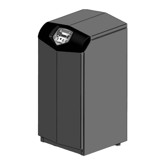
User's Information Manual
Models: 80 - 500
Starting Serial #H05H10003637
WARNING
If the information in this manual is not followed
exactly, a fire or explosion may result causing
property damage, personal injury or loss of life.
This appliance MUST NOT be installed in any
location where gasoline or flammable vapors are
likely to be present.
WHAT TO DO IF YOU SMELL GAS
• Do not try to light any appliance.
• Do not touch any electric switch; do not use any
phone in your building.
• Immediately call your gas supplier from a
neighbor's phone.
Follow the gas supplier's
instructions.
• If you cannot reach your gas supplier, call the fire
department.
• Installation and service must be performed by a
qualified installer, service agency, or the gas
supplier.
Save this manual for future reference.
Advertisement
Table of Contents

Subscribe to Our Youtube Channel
Related Manuals for Lochinvar 80 - 500


Summary of Contents for Lochinvar 80 - 500
- Page 1 User’s Information Manual Models: 80 - 500 Starting Serial #H05H10003637 WARNING If the information in this manual is not followed exactly, a fire or explosion may result causing property damage, personal injury or loss of life. This appliance MUST NOT be installed in any location where gasoline or flammable vapors are likely to be present.
-
Page 2: Table Of Contents
User’s Information Manual Contents Hazard definitions ..........2 Please read before proceeding . -
Page 3: Please Read Before Proceeding
Please read before proceeding The Knight Boiler Installation and Boiler service and maintenance – NOTICE Operation Manual along with the Knight • To avoid electric shock, disconnect electrical supply Boiler Service Manual are for use only by before performing maintenance. -
Page 4: Prevent Combustion Air Contamination
Areas likely to have contaminants boiler combustion air and vent to another location, per the Knight Boiler Installation and Operation Manual. Dry cleaning/laundry areas and establishments Swimming pools To prevent the potential of severe personal... -
Page 5: Maintenance Schedule
User’s Information Manual Maintenance schedule Owner maintenance Service technician (see pages 6 - 8 for detailed instructions) (see the Knight Boiler Service Manual) • Check boiler area General: • Reported problems • Check pressure/temperature gauge • Inspect interior; clean and vacuum if... -
Page 6: Maintenance Procedures
User’s Information Manual Maintenance schedule Maintenance procedures Read the list of potential materials listed in Table 1 on page 4 of this manual. If any of these products are in the room from which the boiler takes its combustion air, they Boiler must be serviced and maintained must be removed immediately or the boiler combustion air (and vent termination) must be relocated to another... - Page 7 3. Slope condensate tubing down and away from the boiler into a drain or condensate neutralizing filter. Condensate from the Knight boiler will be slightly acidic (typically with a pH from 3 to 5). Install a neutralizing filter if required by local codes.
- Page 8 Figure 3 Automatic Air Vent discharge line must be installed by a qualified heating installer or service technician in accordance with the instructions Knight Boiler Installation and Operation Manual. The discharge line must be terminated so as to eliminate possibility of severe burns or property damage should the valve discharge.
-
Page 9: Operating Instructions
User’s Information Manual Operating instructions Models 80 - 285... - Page 10 User’s Information Manual Operating instructions Operating instructions Models 399 - 500...
-
Page 11: Smart System Control Module
User’s Information Manual SMART SYSTEM control module Knight boiler control module Use the control panel (FIG. 4) to set temperatures, operating conditions, and monitor boiler operation. Figure 4 Control Panel... - Page 12 Remember to press the ENTER/RESET button when finished programming in order to save the changes made. Have your qualified service technician reference the Knight Boiler Service Manual for a detailed description of parameters and access modes.
-
Page 13: Parameter Table
User’s Information Manual SMART SYSTEM control module (continued) Parameter table U U S S E E R R A A C C C C E E S S S S I I N N S S T T A A L L L L E E R R A A C C C C E E S S S S S S E E E E M M E E N N U U S S U U B B I I T T E E M M... - Page 14 Boiler model setback feature becomes active. This will require start and The control will display “Knight Boiler” as the model number stop times to be programmed for the days that reduced because the same control is used on several models. This will temperatures are required.
- Page 15 User’s Information Manual SMART SYSTEM control module (continued) E: DHW settings Boost temperature If a SH demand lasts longer than the programmed time delay DHW boiler set point setting and there have been no DHW demands, the control will increase the water temperature set point by the amount When a DHW call for heat becomes active, the control will in this parameter.
-
Page 16: Status Display Screens
User’s Information Manual SMART SYSTEM control module Status Display Screens By using the Previous/Next ( , ) arrow keys on the SMART SYSTEM display panel, you can navigate through the eight (8) display screens. Each screen will contain two (2) viewable items. The following is a description of the individual items and what they can display: Screen Display shows:... - Page 17 User’s Information Manual SMART SYSTEM control module (continued) Status Display Screens (cont’d) By using the Previous/Next ( , ) arrow keys on the SMART SYSTEM display panel, you can navigate through the eight (8) display screens. Each screen will contain two (2) viewable items. The following is a description of the individual items and what they can display: Screen Display shows:...
- Page 18 User’s Information Manual SMART SYSTEM control module Status Display Screens (cont’d) By using the Previous/Next ( , ) arrow keys on the SMART SYSTEM display panel, you can navigate through the eight (8) display screens. Each screen will contain two (2) viewable items. The following is a description of the individual items and what they can display: Screen Display shows:...
-
Page 19: Notes
User’s Information Manual Notes... - Page 20 KB-USER-01 09/05...
Need help?
Do you have a question about the 80 - 500 and is the answer not in the manual?
Questions and answers