
Related Manuals for Lochinvar CP-M Series


Summary of Contents for Lochinvar CP-M Series
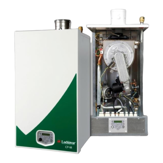
- Page 1 The CP-M+™ range High Efficiency Gas Fired Condensing Boilers Installation, Commissioning & Maintenance Instructions Models: CP-M+60 CP-M+80 CP-M+100 CP-M+120 CP-M+150 CP-M+180 INS0034 Issue No 5 | November 2013...
-
Page 2: Table Of Contents
Table of Contents INTRODUCTION ............................................. 4 PRINCIPAL PARTS ..........................................5 TECHNICAL DATA ..........................................17 GENERAL REQUIREMENTS ....................................... 20 RELATED DOCUMENTS ........................................20 WATER QUALITY ..........................................21 WATER CHEMISTRY ........................................21 AIR/DIRT SEPARATION ........................................21 WATER PRESSURE ......................................... 21 LOCATION ............................................22 PLANT ROOM REQUIREMENTS ..................................... - Page 3 12.0 CONTROL INTERFACE ........................................45 12.1 CONTROL PANEL / DISPLAY UNIT ....................................45 12.2 CONTROL PANEL MENU STRUCTURE ..................................46 12.3 DISPLAY DURING OPERATION ...................................... 47 12.4 MONITOR SCREENS ........................................48 12.5 SERVICE FUNCTION ........................................50 12.6 SCHORNSTEINFEGER FUNCTION ....................................51 12.7 SETTING THE TIME &...
-
Page 4: Introduction
INTRODUCTION The Lochinvar CP-M+™ range is a wall hung gas-fired condensing boiler. The equipment comprises of stainless steel radial burner assembly and heat exchanger that permits fully condensing operation. The burner is initiated by a full electronic ignition sequence control that incorporates a spark ignition and a flame rectification device for supervision of the flame. -
Page 5: Principal Parts
PRINCIPAL PARTS FIGURE 2.1 REMOVABLE COMPONENTS – CP-M+60... - Page 6 FIGURE 2.2 REMOVABLE COMPONENTS – CP-M+60 (CONTINUED)
- Page 7 Item Description Item Description L/H side panel with insulation Flow pipe Front panel with insulation Pump Ignition cable Pump gasket 1½" Ignition electrode with gasket and screws Return pipe – part 1 Heat exchanger rear wall insulation Heat exchanger connection pipe gasket Burner door gasket Heat exchanger connection pipe Burner door insulation...
- Page 8 FIGURE 2.3 REMOVABLE COMPONENTS – CP-M+80 – CP-M+100...
- Page 9 FIGURE 2.4 REMOVABLE COMPONENTS – CP-M+80 – CP-M+100 (CONTINUED)
- Page 10 Item Description Item Description L/H side panel with insulation Pressure sensor Front panel with insulation Pressure sensor gasket Ignition cable Pump gasket 1½" Ignition electrode with gasket and screws Flow pipe – part 2 Heat exchanger rear wall insulation Pump Burner door gasket Heat exchanger connection pipe retaining clip Burner door insulation...
- Page 11 FIGURE 2.5 REMOVABLE COMPONENTS – CP-M+120...
- Page 12 FIGURE 2.6 REMOVABLE COMPONENTS – CP-M+120 (CONTINUED)
- Page 13 Item Description Item Description L/H side panel with insulation Flow pipe – part 3 Front panel with insulation Pressure sensor Ignition cable Pressure sensor gasket Ignition electrode with gasket and screws Pump gasket 1½" Heat exchanger rear wall insulation Flow pipe – part 2 Burner door gasket Pump Burner door insulation...
- Page 14 FIGURE 2.7 REMOVABLE COMPONENTS – CP-M+150 – CP-M+180...
- Page 15 FIGURE 2.8 REMOVABLE COMPONENTS – CP-M+150 – CP-M+180 (CONTINUED)
- Page 16 Condensate water trap drain hose Terminal strip cover Heat exchanger Cable gland Return pipe – part 2 Rubber grommet TABLE 2.4 REMOVABLE COMPONENTS – CP-M+150 – CP-M+180 A replacement parts list is available to download from Lochinvar’s website; please visit www.lochinvar.ltd.uk...
-
Page 17: Technical Data
TECHNICAL DATA Model Number CP-M+60 CP-M+80 CP-M+100 CP-M+120 CP-M+150 CP-M+180 GENERAL DATA Input – G20 – (gross) – kW 61.8 82.5 102.0 123.0 153.0 184.0 Input – G31 – (gross) – kW 60.4 80.8 100.0 121.0 150.0 180.0 Input (net) – kW 55.6 74.3 92.2... - Page 18 Twin pipe Concentric Connections CP-M+ CP-M+ CP-M+ CP-M+ CP-M+ CP-M+ CP-M+ Air Inlet Ø80 Ø100 Ø100 Ø125 Ø125 Ø150 Ø150 Flue Gas Ø80 Ø100 Ø100 Ø80 Ø80 Ø100 Ø100 Flow R 1 ¼” (male) Condensate Flexible hose Ø 25/21 x 750 mm Return R 1 ¼”...
- Page 19 Twin pipe Concentric Connections CP-M+ CP-M+ CP-M+ CP-M+ Air Inlet Ø130 Ø130 Ø150 Ø150 Flue Gas Ø130 Ø130 Ø100 Ø100 Flow R 1 ½” (male) Condensate Flexible hose Ø 25/21 x 750 mm Return R 1 ½” (male) R 1” (male) FIGURE 3.2 DIMENSIONS CP-M+150 &...
-
Page 20: General Requirements
GENERAL REQUIREMENTS The Lochinvar CP-M+™ condensing boiler has been designed to operate trouble free for many years. These instructions should be followed closely to obtain the maximum usage and efficiency of the equipment. PLEASE read the instructions fully before installing or using the appliance. -
Page 21: Water Quality
The Aluminium content of the TDS (Total Dissolved Solids) should not exceed 8.5 ppm. If the above requirements cannot be satisfied, a water treatment specialist must be consulted. Details of companies that provide such a service can be obtained from Lochinvar Limited. 5.2 AIR/DIRT SEPARATION Precautions must be taken to remove air and dirt from the heating system. -
Page 22: Location
LOCATION 6.1 PLANT ROOM REQUIREMENTS The Lochinvar CP-M+ may only be installed in a room that complies with the appropriate ventilation requirements. The Lochinvar CP-M+ can be used as a type C or C appliance. Due to its room sealed design, ventilation allowances for combustion air are not necessary. -
Page 23: Condensate Drain
GAS SUPPLY The Lochinvar CP-M+™ range is suitable for use on second and third family gasses 2H - G20 - 20mbar and 3P - G31 - 37mbar. Details relating to Natural Gas (2H) appear below; for details relating to Propane (3P) please refer to Section 15: LPG FUEL. -
Page 24: Meters
7.2 METERS A new gas meter will be connected to the service pipe by the local gas distributor contractor. An existing gas meter should be checked, preferably by the gas distributor, to ensure that it is adequate to deal with the rate of gas supply required. 7.3 GAS SUPPLY PIPES Supply pipes must be fitted in accordance with IGE/UP/2. -
Page 25: Approved Flue System
CP-M+150 & CP-M+180 boilers are supplied for connection to a twin pipe or conventional flue system. If concentric flue is to be used, a conversion kit will be required. Contact Lochinvar Limited for further details. When used as a Type C (Balanced Flued) appliance, the approved, purpose designed adaptive flue system should be used. -
Page 26: Installation Precautions
When selecting flue gas systems, it is essential that the minimum requirements are met therefore only flue gas materials having the same or better properties than this table shall be used. 8.3 INSTALLATION PRECAUTIONS The approved flue system is rated to 120C max. ... -
Page 27: Worked Example - Conventional Flue
Size Resistance (Pa) Item (mm) CP-M+60 CP-M+80 CP-M+100 CP-M+120 CP-M+150 CP-M+180 Straight tube (per metre) Straight tube (per metre) Straight tube (per metre) 45° Elbow 45° Elbow 45° Elbow 90° Elbow 90° Elbow 90° Elbow Vertical inlet cap 10.4 18.1 Vertical inlet cap 11.4 16.7... -
Page 28: Worked Example - Twin-Pipe Flue
8.5.2 WORKED EXAMPLE – TWIN-PIPE FLUE CP-M+150 boiler with an inlet air duct of 8 metres, 3 x 90° elbows plus a vertical inlet cap and an exhaust duct of 12 metres plus 4 x 90° elbows. Item Quantity Resistance Total Straight tube (m) 90°... -
Page 29: Type C 13 (Horizontal Balanced Flue)
When the heater is installed as a Type B appliance, the flue system should be installed in accordance with the flue manufacturer’s specific instructions. 8.7.2 TYPE C (HORIZONTAL BALANCED FLUE) When the heater is installed as a Type C appliance, the flue system should be installed as follows: Determine the location of the flue terminal, taking into account minimum distances as detailed in Figure 8.1, Table 8.1 and the relevant British Standards. -
Page 30: Type C
FIGURE 8.4 VERTICAL TERMINAL ROOF FLASHINGS FOR SYNTHETIC, FLAT AND TILED ROOFS FIGURE 8.5 INSTALLING TERMINAL THROUGH ROOF FLASHING 8.7.4 TYPE C This appliance can operate on a U-Duct common flue system. The maximum lengths for the interconnecting flue can be calculated using the information in Section 8.5: MAXIMUM LENGTH –... -
Page 31: Flue Terminal Guarding
A cascaded common flue system which operates on a positive pressure is available from Lochinvar Limited. Further details can be found in the Cascade Flue Systems guide, available from www.lochinvar.ltd.uk. -
Page 32: Cooling Ventilation
1.35 ± 0.18 (with or without draught stabilisers) TABLE 9.4 MECHANICAL VENTILATION FLOW RATES 9.3.1 WORKED EXAMPLE – MECHANICAL INLET/NATURAL DISCHARGE Lochinvar CP-M+100 Heat input (net): 92.0 kW Minimum combustion air flow rate: 92.0 x 2.6 m 239.2 m Ventilation grille size (high level):... -
Page 33: Worked Example - Mechanical Inlet/Mechanical Discharge (Minimum Combustion Air Flow Rate)
OPEN VENTED SYSTEM ARRANGEMENT The Lochinvar CP-M+ can be used in an open vented arrangement provided that a vent pipe in accordance with CP 342 or BS6644 as appropriate is fitted. The minimum static head requirement for an open vented system is 1.0 bar. -
Page 34: Sealed System Arrangement
SEALED SYSTEM ARRANGEMENT If a sealed system arrangement is required, a suitable pressurisation unit is available from Lochinvar Limited on request. Sealed systems should incorporate a safety valve with a lift pressure no greater than the maximum pressure rating of any component in the heating system. - Page 35 Hydraulic graph 60kW ΔT=25K ΔT=20K Water flow (m³/h) Resistance Boiler Head Pump Head for Installation FIGURE 10.1 HYDRAULIC GRAPH – CP-M+60 Hydraulic graph 80kW ΔT=25K ΔT=20K Water flow (m³/h) Resistance Boiler Head Pump Head for Installation FIGURE 10.2 HYDRAULIC GRAPH – CP-M+80...
- Page 36 Hydraulic graph 100kW ΔT=20K ΔT=25K Water flow (m³/h) Resistance Boiler Head Pump Head for Installation FIGURE 10.3 HYDRAULIC GRAPH – CP-M+100 Hydraulic graph 120kW ΔT=25K ΔT=20K Water flow (m³/h) Resistance Boiler Head Pump Head for Installation FIGURE 10.4 HYDRAULIC GRAPH – CP-M+120...
- Page 37 Hydraulic graph 150 kW ΔT=25K ΔT=20K Water flow (m³/h) resistance boiler head pump s2 head for installation s2 head pump s3 head for installation s3 FIGURE 10.5 HYDRAULIC GRAPH – CP-M+150 Hydraulic graph 180 kW ΔT=20K ΔT=25K Water flow (m³/h) Resistance Boiler Head pump s2 Head for installation s2...
-
Page 38: Dirt Separator/Strainer
A low-water level protection device should also be installed within the system. 10.8 INSTALLATION SCHEMATIC DRAWINGS The following schematic drawings are for guidance purposes only. Alternate installation schematic drawings are available; please visit www.lochinvar.ltd.uk. - Page 39 LOCKSHIELD VALVE DRAIN VALVE AIR SEPARATOR DIRT SEPARATOR AUTOMATIC AIR VENT EXPANSION VESSEL TEMPORARY FILL CONNECTION (REMOVE AFTER FILLING) DOUBLE CHECK VALVE LOW VELOCITY HEADER NON RETURN VALVE PRESSURE RELIEF VALVE ISOLATION VALVE MANUAL AIR VENT STRAINER FIGURE 10.7 SINGLE BOILER INSTALLATION ON A SEALED SYSTEM...
- Page 40 LOCKSHIELD VALVE DRAIN VALVE AIR SEPARATOR DIRT SEPARATOR AUTOMATIC AIR VENT EXPANSION VESSEL TEMPORARY FILL CONNECTION (REMOVE AFTER FILLING) DOUBLE CHECK VALVE LOW VELOCITY HEADER NON RETURN VALVE PRESSURE RELIEF VALVE ISOLATION VALVE MANUAL AIR VENT STRAINER CASCADE FLOW SENSOR FIGURE 10.8 MULTIPLE BOILER INSTALLATION ON A SEALED SYSTEM...
-
Page 41: Electrical Supply
11.0 ELECTRICAL SUPPLY Wiring external to the equipment must be installed in accordance with the I.E.E. Regulations and any local regulations that apply. Normal Supply External Fuse Model Power Consumption Voltage Rating CP-M+60 CP-M+80 230V AC CP-M+100 50 Hz 6.0 Amps CP-M+120 1 PH CP-M+150... - Page 42 When an “Open-Therm” room thermostat is connected, it should be connected to terminals ‘7’ and ‘8’ using screened cable. The boiler is ready for use with a multifunctional room controller (such as the Lochinvar RC Controller). For further information, please see the controller specific manual.
-
Page 43: Arc Welding Precautions
11.5 TIME, TEMPERATURE AND ZONE CONTROL Lochinvar can supply time, temperature and zone control options for a variety of heating system installations. For further details, please refer to the Systems and Controls Guide, available from www.lochinvar.ltd.uk. -
Page 44: Cp-M+ Wiring Diagram
11.6 CP-M+ WIRING DIAGRAM internal connections ionisation and/or ignition siphon pressure switch (PSW) N.C. display ref.1 boiler casing clixon/maximum (S6/S7) water thermostat 24vdc CN15 ignition transformer incl. ionisation input. WIRING COLORS K0=white K6=blue fan Hall CN10 fan control fan PWM K1=yellow K7=red +24Vdc... -
Page 45: Control Interface
12.0 CONTROL INTERFACE 12.1 CONTROL PANEL / DISPLAY UNIT CONTROL PANEL DISPLAY 2 rows / each 20 characters ON/OFF MENU RESET ENTER SERVICE COMM. PORT Press and hold for 6 seconds to switch boiler on/off. ON/OFF RESET Is also used as RESET button and ENTER button when ENTER programming. -
Page 46: Control Panel Menu Structure
12.2 CONTROL PANEL MENU STRUCTURE CONFIRMATION CHANGE ! BASE SCREEN : (what shows during operation) When changes are being made in the menu's within this dashed H E A T I N G : S t a n d - b y rectangle, the user presses ENTER to confirm the changes. -
Page 47: Display During Operation
12.3 DISPLAY DURING OPERATION During normal operation the text in the display shows the status of the boiler. In the following figures the possble displays during normal operation are explained. Display during HEATING DEMAND Heat demand type: Actual status: H E A T A N D >... -
Page 48: Monitor Screens
12.4 MONITOR SCREENS During normal operation and stand-by, the “◄” and “►” buttons can be used to show some boiler information, including measured temperatures, settings and data. The following figure explains which values can be shown in the display. When no button is activated for 2 minutes the display will return to its status display. Pressing [◄] or [►] when the display shows the "operating screen"... - Page 49 SCREEN: C a s c D e s i g n Shows the cascade address of the boiler 0 = MASTER, 1 ..11 = SLAVES C a s I n 0 1 2 3 4 5 6 7 8 9 A B Displays number, priority and state of cascade boilers. (See below) SCREEN: C a s c P o w e r...
-
Page 50: Service Function
12.5 SERVICE FUNCTION The following figure describes how to use the service function. Operating screen: H E A T I N G : S T A N D - B Y > > > 1 2 3 . 1 2 3 . Press [SERVICE] and hold for 3 seconds. -
Page 51: Schornsteinfeger Function
12.6 SCHORNSTEINFEGER FUNCTION The following figure describes how to use the Schornsteinfeger function. NOTE: This function is only required in Germany and can be activated by parameter (P5 BK). By default, this function is disabled. ENGELSE UITVOERING "SCHORNSTEINFEGER" function The purpose of this function is to have an easy interface for the "Schorsteinfegers" in Germany, to be able to do their required testing on the boiler. -
Page 52: Setting The Time & Date
12.7 SETTING THE TIME & DATE The following figure describes how to program the time and date of the unit. Operating screen: H E A T I N G : S T A N D - B Y > > > 1 2 3 . -
Page 53: Setpoints
12.8 SETPOINTS The following figure describes how to program the heating and hot water set points. Operating screen: H E A T I N G : S T A N D - B Y > > > 1 2 3 . 1 2 3 . -
Page 54: Setting The Timer Programs
12.9 SETTING THE TIMER PROGRAMS Three different programs can be set with the boiler, these are: Central Heating (CH) program Domestic Hot Water (DHW) program Anti legionnaire’s disease (pasteurisation) program NOTE: The anti legionnaire’s disease (pasteurisation) program can only be used when the boiler is set as an “indirect”... - Page 55 > > > From previous page < < < Copy programmed day for CH: C o p y r o m : M o n C o p y T u e Press [►] to switch between "Copy from" and "Copy to". The flashing day is selected and can be changed.
- Page 56 > > > From previous page < < < Copy programmed day for DHW: C o p y r o m : D H W M o n C o p y D H W T u e Press [►] to switch between "Copy from" and "Copy to". The flashing day is selected and can be changed.
-
Page 57: Outside Temperature Compensation
12.10 OUTSIDE TEMPERATURE COMPENSATION 12.10.1 MAIN PARAMETERS FOR SETTING THE COMPENSATED HEATING CURVE HEATING CURVE - main settings P5 AD - Flow temp at outside temp low P6 BC - Parallel shift P5 AF - Flow temp at outside temp high OUTSIDE TEMPERATURE P5 AE P5 AC... -
Page 58: Additional Parameters For Setting The Compensated Heating Curve
12.10.1 ADDITIONAL PARAMETERS FOR SETTING THE COMPENSATED HEATING CURVE HEATING CURVE - additional settings P6 BA - max flow temp P6 BB - Heatcurve night shift P5 AH - Warm weather shutdown P2 HA - Outdoor sensor hysteresis P5 AG - min flow temp OUTSIDE TEMPERATURE FIGURE 12.14 COMPENSATED HEATING CURVE –... -
Page 59: Setting Outside Temperature Compensation
12.10.2 SETTING OUTSIDE TEMPERATURE COMPENSATION The following figure describes how to program the outside temperature compensation curve. Operating screen: H E A T I N G : S T A N D - B Y > > > 1 2 3 . 1 2 3 . -
Page 60: Checking The Operating History
12.11 CHECKING THE OPERATING HISTORY The following figure describes how to check the operating history of the boiler. Operating screen: H E A T I N G : S T A N D - B Y > > > 1 2 3 1 2 3 . -
Page 61: Checking The Fault History
12.12 CHECKING THE FAULT HISTORY The following figure describes how to check the fault history of the boiler. Operating screen: H E A T I N G : S T A N D - B Y > > > 1 2 3 1 2 3 . -
Page 62: Setting The Maintenance Specifications
12.13 SETTING THE MAINTENANCE SPECIFICATIONS The following figures describe how to check and program the maintenance settings. The standard factory setting for this function is “OFF”. MAINTENANCE SETTINGS The unit can be programmed in such a way that an automatic maintenance message is displayed. There are three options that can be selected. - Page 63 > > > From previous page < < < Screen: Selecting message at certain date. M a i n M o d e D a t Press [►] to set: The date for the maintenance message. Press [◄] to: Return to maintenance mode selection. Press [►] to browse through the values that can be set at the bottom line.
- Page 64 > > > From previous page < < < Screen: Message after total amount of burning hours. M a i n M o d e B u r n i n g h o u r Press [►] to set: The total amount of burning hours for the Maintenance message.
-
Page 65: Setting The User Lock
12.14 SETTING THE USER LOCK When the user lock function is activated, it prevents accidental changes being made to the operating characteristics of the boiler. It should be noted that whilst access to the basic settings is disabled, the parameter menus can still be accessed using the required passwords. -
Page 66: Parameters
13.0 PARAMETERS 13.1 SETTING THE PARAMETERS WITH THE DISPLAY MENU The operating parameters of the boiler are embedded in the burner control system electronics. Some of the values and settings that are used to control the boiler operation can be changed by modifying these parameters in order to configure the appliance to meet the specific requirements of the installation. - Page 67 Operating screen: H E A T I N G : S T A N D - B Y > > > 1 2 3 1 2 3 Press [MENU] Select "Parameter" using [◄] & [►] M e n u P a r a m e t Press [ENTER] Parameter menu:...
- Page 68 > > > From previous page < < < Menu A: Heating c P r b This parameter sets the Cascade CH proportional band. This is the temperature range below the setpoint temperature in which each boiler in the cascade boiler will modulate (as measured by the cascade sensor).
- Page 69 > > > From previous page < < < Menu B: Hot water L e g M i n This parameter sets the time period that the pasteurisation function runs for. Menu B: Hot water L e g This parameter determines whether a pasteurisation demand takes priority over a CH demand over the boiler.
- Page 70 > > > From previous page < < < Menu C: Cascade M a x C a s c U n This parameter sets the maximum number of slave boilers within a cascade. The maximum number is 11 therefore this parameter should not be changed. Menu C: Cascade B u s a d r...
- Page 71 > > > From previous page < < < Menu D: General 1 0 M i n T m p When Parameter D1 set to '1' (temperature control) this parameter sets the temperature required with a signal of 1 Volt Menu D: General 1 0 0 f This function is not used on the CP-M+ boiler and should not be adjusted.
-
Page 72: Commissioning And Testing
14.0 COMMISSIONING AND TESTING 14.1 ELECTRICAL INSTALLATION Notes on the requirements for electrical installation are provided in Section 11: ELECTRICAL SUPPLY. A schematic drawing of the control circuit is shown in Figure 11.2 14.2 GAS INSTALLATION For design see Section 7: GAS SUPPLY. See Figure 3.1 or Figure 3.2 for details on the position of the gas connection. -
Page 73: Procedure For Initial Lighting
14.4.3 PROCEDURE FOR INITIAL LIGHTING IF THE UNIT IS TO OPERATE ON LPG REFER TO SECTION 15.2 BEFORE PROCEEDING Ensure that the gas-inlet appliance isolating valve, provided by the installer, is in the “off” position. Turn on the local electrical isolator, to bring the equipment on. The boiler will go through a de-aeration sequence of starting and stopping the integral pump three times. -
Page 74: Temperature Adjustment Procedure
The most effective way of setting the heat source is through the use of a CO measuring device such as a flue gas analyser. The procedure is as follows: Put the boiler into ‘Service Mode’. This is done by depressing the service button for three seconds. The display should show: Display message H E A T... -
Page 75: Lpg Fuel
15.0 LPG FUEL NOTE! IT IS STRONGLY RECOMMENDED THAT, ON LPG INSTALLATIONS, GAS DETECTION EQUIPMENT IS FITTED. THIS EQUIPMENT SHOULD BE POSITIONED NEAR THE APPLIANCE AND AT LOW LEVEL. IT IS ALSO IMPORTANT THAT THE SPACE HOUSING THE APPLIANCE IS ADEQUATELY VENTILATED AT HIGH AND LOW LEVEL. - Page 76 On models CP-M+120, CP-M+150 & CP-M+180, remove the screw from the outlet pressure test point of the left hand gas valve (identified as screw 4 in Figure 15.1) and attach a manometer. Put the boiler into ‘Service Mode’. This is done by depressing the service button for three seconds. If the burner does not light after three attempts, turn screw 2 through ¼...
-
Page 77: Maintenance
16.0 MAINTENANCE 16.1 GENERAL KEEP APPLIANCE AREA CLEAR AND FREE FROM COMBUSTIBLE MATERIALS AND FLAMMABLE VAPOURS AND LIQUIDS. A competent person should check and ensure that the flue, its support and terminal, the ventilation to the boiler house, safety valve, drain, pressure gauge etc. are in a serviceable and working condition and still comply with the relevant standards and codes of practice, as detailed in Section 4: GENERAL REQUIREMENTS. -
Page 78: Burner Removal
16.3 BURNER REMOVAL If it has been determined that the flame picture is unacceptable, the burner can be removed and cleaned using the following procedure: Isolate the electrical and gas supplies to the heater. Allow the boiler to cool down. Disconnect the wiring connections to the ignition electrode. -
Page 79: Cleaning The Heat Exchanger
NOTE: A kit of components to aid with cleaning the heat exchanger is available from Lochinvar Limited. For models CP-M+60 – CP-M+120 use part number KIT30063, for models CP-M+150 & CP-M+180 use part number KIT30064. -
Page 80: Other Checks
16.7 OTHER CHECKS 16.7.1 RELIEF VALVES (IF FITTED) At least once a year, the pressure relief valve should be checked to ensure correct operation. To check the valve, lift the lever or turn the screw cap at the end of the valve several times. The valve should operate freely and seat properly. -
Page 81: Setting A Replacement Gas Valve
16.8 SETTING A REPLACEMENT GAS VALVE When a replacement gas valve is fitted, the following procedure must be carried out in the order stated when the boiler is switched on for the first time. Failure to follow the following procedure may lead to non-warrantable damage to the boiler. - Page 82 Put the boiler into ‘Service Mode’. This is done by depressing the service button for three seconds. If the burner does not light after three attempts, turn screw 2 through ¼ turn counter clockwise. On the CP-M+ 120, CP-M+150 and CP-M+180, this adjustment should be made to the right hand gas valve only.
-
Page 83: Troubleshooting
17.0 TROUBLESHOOTING To avoid electric shocks, disconnect electrical supply before performing troubleshooting. To avoid burns, allow the unit to cool before performing troubleshooting. Be aware that a fault code is an indication that the unit or the system needs attention. When a fault occurs repeatedly remedial work should be undertaken by a suitably qualified person. - Page 84 Display message e m p u m p Reason: Maximum return temperature exceeds limit value. Cause: An external heat source (CHP, heat pump etc.) has heated the return temperature above the maximum return temperature. Corrective Action: Reduce pre heat temperature of external heat source. Cause: The external heating controls suddenly close causing excessive return water temperature.
- Page 85 Bleed all air from the unit so the heat from combustion can be transferred to the water and won't leave through the flue Cause: Heat exchanger failure. Corrective Action: Contact Lochinvar Limited for further guidance. Display message u m p Reason Boiler not operational after 4 starting attempts.
- Page 86 Display message a m e u m p Reason Flame signal lost during operation. Cause: Incorrect gas supply pressure. Corrective Action: Be aware that the nominal gas inlet pressure must be met under all operation conditions. Check the incoming gas supply pressure is correct. Contact the gas transported if incorrect. Check if all gas valves in the supply line are completely open.
- Page 87 Heat exchanger fuse exceeded maximum value. Cause: The heat exchanger thermal fuse has opened permanently. Corrective Action: Isolate the electrical power and gas supply to the boiler and contact Lochinvar Limited for further guidance. Display message u m p Reason: High-temperature limit thermostat has exceeded the limitation value.
-
Page 88: Blocking Codes
Display message u m p Reason: Siphon pressure switch detects high pressure in the flue/condensate drain system. Cause: There is too much resistance in the flue system causing excessive pressure in the heat exchanger. Corrective Action: Check if the flue system is blocked. Check the condition of the heat exchanger and clean if necessary. - Page 89 Bleed all air from the unit so the heat from combustion can be transferred to the water and won't leave through the flue Cause: Heat exchanger failure. Corrective Action: Contact Lochinvar Limited for further guidance. Display message Reason The controller received a new heat demand too soon after the last heat demand finished.
- Page 90 Display message Reason System water pressure is too high or too low. Cause: The water pressure in the system is too high. Corrective Action: Check if the system pressure is too high after (re)filling. Check the settings of any automatic pressurisation unit attached to the system. Make sure that there is a pressure relief valve and expansion vessel installed in the system, according to the applicable standards.
-
Page 91: Important Messages
Display message G e n Reason The general blocking circuit is activated during operation (after a flame was rectified). Cause: The circuit connected to the general blocking terminals is not closed. Corrective Action: Check all external safety devices that are in the circuit connected to the general blocking terminals, and determine why the contact is not closed during heat demand. - Page 92 NOTES NOTES __________________________________________________________________________________ __________________________________________________________________________________ __________________________________________________________________________________ __________________________________________________________________________________ __________________________________________________________________________________ __________________________________________________________________________________ __________________________________________________________________________________ __________________________________________________________________________________ __________________________________________________________________________________ __________________________________________________________________________________ __________________________________________________________________________________ __________________________________________________________________________________ __________________________________________________________________________________ __________________________________________________________________________________ __________________________________________________________________________________ __________________________________________________________________________________ __________________________________________________________________________________ __________________________________________________________________________________ __________________________________________________________________________________ __________________________________________________________________________________ __________________________________________________________________________________ __________________________________________________________________________________ __________________________________________________________________________________ __________________________________________________________________________________ __________________________________________________________________________________ __________________________________________________________________________________ __________________________________________________________________________________ __________________________________________________________________________________ __________________________________________________________________________________ __________________________________________________________________________________ __________________________________________________________________________________...
- Page 93 NOTES NOTES __________________________________________________________________________________ __________________________________________________________________________________ __________________________________________________________________________________ __________________________________________________________________________________ __________________________________________________________________________________ __________________________________________________________________________________ __________________________________________________________________________________ __________________________________________________________________________________ __________________________________________________________________________________ __________________________________________________________________________________ __________________________________________________________________________________ __________________________________________________________________________________ __________________________________________________________________________________ __________________________________________________________________________________ __________________________________________________________________________________ __________________________________________________________________________________ __________________________________________________________________________________ __________________________________________________________________________________ __________________________________________________________________________________ __________________________________________________________________________________ __________________________________________________________________________________ __________________________________________________________________________________ __________________________________________________________________________________ __________________________________________________________________________________ __________________________________________________________________________________ __________________________________________________________________________________ __________________________________________________________________________________ __________________________________________________________________________________ __________________________________________________________________________________ __________________________________________________________________________________ __________________________________________________________________________________...
Need help?
Do you have a question about the CP-M Series and is the answer not in the manual?
Questions and answers