Lochinvar Power-Fin Series Installation And Service Manual
500,000, 750,000, 1,000,000 and 1,300,000 btu/hr models
Hide thumbs
Also See for Power-Fin Series:
- Designer's manual (48 pages) ,
- Designer's manual (48 pages)
Table of Contents
Advertisement
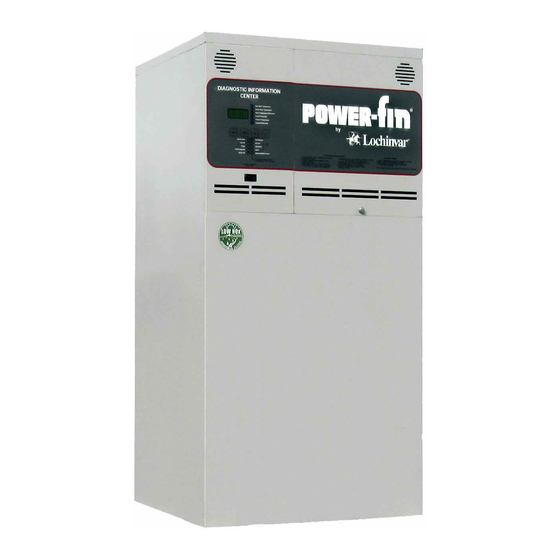
INSTALLATION AND SERVICE MANUAL
500,000, 750,000, 1,000,000 and 1,300,000 Btu/hr MODELS
FIG. 1 Front View
WARRANTY
Installation and service must be performed by a qualified
service installer, service agency or the gas supplier.
Factory warranty (shipped with unit) does not apply to units
improperly installed or improperly operated.
Experience has shown that improper installation or system
design, rather than faulty equipment, is the cause of most
operating problems.
1. Excessive water hardness causing a lime/scale build-up in
the copper tube is not the fault of the equipment and is not
covered under the manufacturer's warranty (see Water
Treatment and Water Chemistry).
2. Excessive pitting and erosion on the inside of the copper
tube may be caused by too much water velocity through the
tubes and is not covered by the manufacturer's warranty
(see Boiler Flow Rates and Temperature Rise for flow
requirements).
Power-Fin
HOT WATER HEATING BOILERS
DOMESTIC WATER HEATERS
NOTE:
This manual supplies information for the installation, operation
and servicing of the appliance. It is strongly recommended that
this manual be reviewed completely before proceeding with an
installation.
Upon receiving equipment, check for signs of shipping
damage. Pay particular attention to parts accompanying the
boiler, which may show signs of being hit or otherwise being
mishandled. Verify total number of pieces shown on packing
slip with those actually received. In case there is damage or a
shortage, immediately notify carrier.
®
SPECIAL INSTRUCTIONS
TO OWNER
Retain this manual for future reference.
WARNING
IMPROPER
INSTALLATION, ADJUSTMENT,
ALTERATION, SERVICE OR MAINTENANCE can
cause injury or property damage. Refer to this manual.
For assistance or additional information, consult a
qualified installer, service agency or the gas supplier.
CHECKING EQUIPMENT
DO NOT:
DO NOT USE THIS APPLIANCE IF ANY PART
HAS BEEN UNDER WATER. THE POSSIBLE
DAMAGE TO A FLOODED APPLIANCE CAN
BE EXTENSIVE AND PRESENT NUMEROUS
SAFETY HAZARDS. ANY APPLIANCE THAT
HAS
BEEN
UNDER
REPLACED.
PB-PF-i&s-03
WATER
MUST
BE
Advertisement
Table of Contents

Related Manuals for Lochinvar Power-Fin Series


Summary of Contents for Lochinvar Power-Fin Series
-
Page 1: Warranty
PB-PF-i&s-03 INSTALLATION AND SERVICE MANUAL Power-Fin ® HOT WATER HEATING BOILERS DOMESTIC WATER HEATERS 500,000, 750,000, 1,000,000 and 1,300,000 Btu/hr MODELS SPECIAL INSTRUCTIONS TO OWNER NOTE: Retain this manual for future reference. This manual supplies information for the installation, operation and servicing of the appliance. -
Page 2: Table Of Contents
Gas Piping ........21 WARNING Gas Manifold Pressure Adjustment . -
Page 3: Codes
Pump Operation ......50 3. UNDER NO CIRCUMSTANCES must flammable materials such as gasoline or paint thinner be used or Thermostat Settings . -
Page 4: Clearances
CLEARANCES FROM COMBUSTIBLE CONSTRUCTION FIG. 2 Clearances from Combustible Construction - Front & Rear View 7. This appliance may condense the products of combustion Maintain minimum specified clearances for adequate when operating at water temperatures below 140°F (60°C). operation. All installations must allow sufficient space for Ensure that the appliance is located near an acceptable servicing the vent connections, water pipe connections, piping drain where condensate that may form in the venting... - Page 5 FIG. 3 Combustion Air Direct from Outside FIG. 5 Combustion Air from Interior Space 3. If air is taken from another interior space, each of the two 1. If air is taken directly from outside the building with no openings specified above should have a net free area of one duct, provide two permanent openings: square inch for each 1000 Btu (22 cm per kW) of input, but...
-
Page 6: Combustion Air Supplied To The Equipment Room
TABLE — B Minimum Recommended Combustion Air Supply to Equipment Room COMBUSTION AIR SOURCE Boiler Outside Air* Outside Air* Inside Air Input 2 - Openings 1 - Opening 2 - Openings 500,000 125 in (806 cm 167 in (1,077 cm (500 in ) (3,226 cm 750,000... -
Page 7: General Venting Information
termination with a sealed Category IV flue and combustion air All venting applications where combustion air is drawn from supplied from the equipment room. the equipment room must have adequate combustion and ventilation air supplied to the equipment room in accordance (3) Vertical DirectAire Venting which uses a vertical negative with the latest edition of the National Fuel Gas Code, ANSI draft flue with a rooftop termination for flue products and a... - Page 8 reason, the flue must be reassembled and resealed according to Category IV General Venting Information the vent manufacturer’s instructions. A Category IV venting system operates with a positive pressure in the vent. This positive pressure is generated by the internal The flue may terminate either vertically at the rooftop or combustion air blower which operates the combustion process horizontally on a sidewall.
-
Page 9: Common Venting Systems
Flue gas condensate can freeze on exterior surfaces or on the vent cap. Frozen condensate on the vent cap can result in a blocked flue condition. Flue gas condensate can cause discoloration of exterior building surfaces. Adjacent brick or masonry surfaces should be protected with a rust resistant sheet metal plate. -
Page 10: Conventional Vertical Category I Negative Draft
resized to approach the minimum size as determined using Units that may be vented with a Category I, Type “B” vent the appropriate tables in Appendix G in the latest edition of material operate with ON/OFF burner firing. A unit with the National Fuel Gas Code, ANSI Z223.1, in Canada, the ON/OFF burner operation can be identified by the “Category I latest edition of CGA Standard B149 Installation Code for... -
Page 11: Sidewall Venting
Category IV Flue Pipe Materials Common Venting System You can combine the flue with the vent from other negative Select venting material from the following specified vent draft Category II appliances ONLY. The vent from other distributors: Category I appliances CANNOT be combined with the flue Heat-Fab Inc., Saf-T CI Vent with AL29-4C stainless steel from Category II appliances unless the entire vent system for (Call 1-800-772-0739 for nearest distributor) - Page 12 Maximum Vent Length Air Requirements section to ensure that adequate combustion and ventilation air is supplied to the equipment room. All other The installed length of the Category IV flue from the appliance general installation requirements must be followed. to the point of termination, outside of the building must not Location of a Sidewall Vent Termination exceed a maximum of 50 equivalent feet (15.2m) in length.
-
Page 13: Direct Vent And Directaire Vent Systems
The sidewall vent system must use the sidewall vent cap kit Air Inlet Pipe Materials provided by the appliance manufacturer for installation on a The air inlet pipe(s) must be sealed. Choose acceptable sidewall termination. combustion air inlet pipe materials from the following list: The sidewall vent cap MUST be purchased as a kit from the PVC, CPVC or ABS (5"... -
Page 14: Directaire Vent Systems
connected to the common air inlet. This exterior opening for DANGER combustion air must connect directly to the outdoors. The total length of the combined air inlet pipe must not exceed a Failure to properly seal all joints and seams as required in maximum of 50 (15.2m) equivalent feet. -
Page 15: Vertical Directaire W/Sidewall Combustion Air
In cold climates, the use of Type “B” double-wall vent pipe or VERTICAL DIRECTAIRE WITH an insulated single-wall pipe is recommended to help prevent SIDEWALL COMBUSTION AIR moisture in the cool incoming air from condensing and leaking from the inlet pipe. CAUTION Appliances that are shut down or will not operate may experience freezing due to convective airflow in the air inlet... -
Page 16: Vertical Directaire Venting W/Rooftop Combustion Air
venting flue products to the outdoors. All other general problems with the heater and possible spillage of flue products installation requirements must be followed. that can cause personal injury, death, or property damage. The termination point of the sidewall air inlet must be installed The maximum installed length of the Category IV flue from the a minimum of 12 inches (0.30m) above ground level and above appliance to the point of termination must not exceed 50... -
Page 17: Horizontal Directaire W/Vertical Combustion Air
Vent Systems are installed with the flue outlet and combustion Vertical Combustion Air Inlet air intake located in different pressure zones. Follow all requirements in the Sidewall Venting and Category IV General Venting Information sections for proper installation and for venting flue products horizontally out a sidewall to the outdoors. -
Page 18: Vertical Direct Vent Systems
VERTICAL DIRECT VENT SYSTEMS This vent option is only available on units with modulating burner firing. The unit can be identified by the “Category IV” and the “M” prefix on the firing controls as noted on the unit’s rating plate. A Vertical Direct Vent System is installed with a Category IV flue and a separate combustion air pipe to the outdoors. - Page 19 Vertical Combustion Air Inlet The Direct Vent System always requires the installation of an additional pipe to supply combustion air from outdoors directly Follow the vertical combustion air inlet material and location to the appliance. The air inlet pipe must use one of the requirements as listed in the Vertical DirectAire Venting with materials specified in the Air Inlet Pipe Materials section.
-
Page 20: Gas Supply
TABLE — G GAS SUPPLY Horizontal Direct Vent Kits Verify that the appliance is supplied with type gas specified on Flue Alt. Alt. Input Horizontal rating plate. This appliance is orificed for operation up to 4000 Inlet Flue Horizontal Btu/hr DV Kit feet altitude. -
Page 21: Gas Connection
3. Install a manual main gas shutoff valve at the units gas inlet, GAS PRESSURE TEST outside of the appliance and before the gas valve. Install a union at the appliance gas line connection for ease of 1. The appliance must be disconnected from the gas supply service and removal of the gas train. -
Page 22: Gas Piping
GAS PIPING FIG. 26 Gas Train Assembly - M9 Venting of Gas Valves and Pressure Switches The diaphragm type gas valve and optional gas pressure switches are provided with threaded termination points to be FIG. 27 Gas Line Connection with Sediment Trap and vented to the atmosphere, outside the building, if required by Manual Main Gas Shut-off Valve local codes. -
Page 23: Checking Manifold Gas Pressure
5. Turn the power switch to “ON” position. GAS MANIFOLD 6. Adjust the temperature set point on the Diagnostic PRESSURE ADJUSTMENT Information Center to call for heat. The manifold gas pressure on the Power-Fin appliance is not 7. Observe the gas supply pressure as the burner fires at 100% field adjustable. -
Page 24: Water Connections
As the appliance comes on and fires, record the inches of CHECKING MANIFOLD GAS water column of displacement on both sides of the PRESSURE manometer. The sum of these two readings will be the gas manifold pressure. The manifold gas pressures for the single-stage (F9) and modulating (M9) models are shown below in Table L. -
Page 25: Heat Exchanger
ELECTRICAL CONNECTIONS HEAT EXCHANGER The heat exchanger is composed of two circular, glass lined, and cast iron headers with 24 vertical finned copper tubes. MINIMUM WATER TEMPERATURES A minimum return water temperature of 140°F (60°C) has been established to control condensate formation based on the Btu/hr output at rated burner input. -
Page 26: Access To Components And Controls
A component, transformer and relay mounting control panel is TABLE — M located along the right side of the exterior jacket panel. This AMP Draw Data panel contains a 75VA transformer to drop 120 VAC to 24 500,000 through 1,300,000 Btu/hr VAC for internal control operation. - Page 27 Shutdown: The Shutdown knob specifies the outdoor air TABLE — N lockout temperature at which the control would prevent the unit Maximum Set Point Determination from operating. This feature can be disabled / enabled with the O.A. shutdown switch. Max. Set Point Outdoor Air Max Temperature (O.A.
-
Page 28: Diagnostic Information Center - F9
temperatures rise, the control will decrease the temperature Do not locate temperature sensor wiring near welding setting of the boiler. You can set the control to shut the boiler equipment. off when a desired outdoor air temperature level is reached. Make sure good mechanical connections are made to the sensor, any interconnecting wiring and the controller. -
Page 29: Led Display
Trial for Ignition: This yellow LED indicates that the hot DATA POINTS VISIBLE FROM surface igniter is turned on for a normal ignition sequence. THE DIAGNOSTIC When illuminated, the ignition module is providing power to INFORMATION CENTER the hot surface igniter. Burner On: This green LED indicates that the gas valve is The following data points are shown in the digital display on energized. -
Page 30: Electronic Temperature Control - Modulating Burner
ELECTRONIC TEMPERATURE DATA POINTS VISIBLE FROM THE CONTROL FOR MODULATING DIAGNOSTIC INFORMATION CENTER BURNER - M9 The following data points can be readily displayed by pressing the SELECT key until the corresponding LED is illuminated. There are up to ten LED's that can be selected to indicate data that can be shown in the digital display. -
Page 31: Status Led's
Outdoor Air Maximum Temperature: This is the highest FAULT STATUS LED’S outdoor air temperature that will be used to reset the boiler. Typically, this would be 60°F, which would mean that the actual Four Fault Status LED's are located on the Diagnostic set point would begin to increase, when the outdoor air Information Center and serve to indicate operational temperature falls below this setting. -
Page 32: Temperature Adjustment Procedure
TEMPERATURE ADJUSTMENT OUTDOOR RESET PROCEDURE FUNCTION SELECTIONS (1) Press the SELECT key until the desired adjustable item's The Electronic Temperature Controller is equipped with an LED is illuminated and its' current setting is displayed. outdoor reset function. This function uses a sensor to measure the outdoor temperature and automatically adjust the boiler set (2) Within 5 seconds of releasing the select key, press either an point temperature to compensate for colder outdoor... -
Page 33: User Lockout Procedure
LIMITED ACCESS FEATURES USER LOCK OUT PROCEDURE Limited access features are features or settings that may The controller has a method to discourage the casual or significantly affect the operation of the controller and display of otherwise inadvertent changing of established settings by an information if they are set incorrectly. -
Page 34: Error Displays
current pump setting being displayed. Press the UP or DOWN ERROR DISPLAYS key to scroll through all available pump settings (On, 30, 60 or 90). Repeated pressing and releasing of a single key will slowly The digital display in the Diagnostic Information Center may step the display through all available settings. -
Page 35: Condensate Trap Installation
12. A 1/2" pipe connection is supplied on the condensate trap. NOTE: Connect a suitable pipe or tube to this connection (see Figure 43). The high limit control will not reset until the water temperature has dropped below the set point of the high WARNING limit. -
Page 36: Hot Surface Ignition System
TABLE — P HOT SURFACE Ignition Module Status LED Diagnostic Codes IGNITION SYSTEM Code Sequence Condition Ignition Module Lockout Functions System OK, no faults present. The ignition module may lockout in either a hard lockout Constant ON Possible control fault, check power; condition requiring pushing of the reset button to recycle the LED may be defective, do not Constant OFF... -
Page 37: Lighting Instructions
LIGHTING INSTRUCTIONS FOR YOUR SAFETY, READ BEFORE OPERATING WARNING If you do not follow these instructions exactly, a fire or explosion may result causing property damage, personal injury or loss of life. A. This appliance does not have a pilot. It is equipped with an ignition device which automatically lights the burner. -
Page 38: To Turn Off Gas To Appliance
WARNING: Should overheating occur or the gas fail to shut off, turn off the manual gas control valve to the appliance. IGNITION SYSTEM CHECKOUT Set power switch to “ON” position. 2. Turn off gas supply to appliance. Set the Set point Temperature function of the Diagnostic Information Center and high limit controls to the highest setting 4. -
Page 39: Maintenance
11. On M9 models the Blower cycles down to 75% speed and 2. VISUALLY CHECK MAIN BURNER FLAMES at each the Ignition Module initiates the heat-up sequence of the start up after long shutdown periods or at least every six Hot Surface Igniter. -
Page 40: Burner Removal And Cleaning
4. Disconnect the gas supply connection to the internal gas NOTE: train at the field installed union. Remove the air inlet pipe connection to the boiler/water All gaskets/sealants on disassembled components or heater. jacket panels must replaced with gaskets/sealants on re-assembly. Gasket and sealant Disconnect the power wires to the gas valves, flow switch, kits are available from your distributor. - Page 41 8. Ensure that the fiber gasket used to seal the base of the Use a vacuum to remove loose soot from surfaces and inner igniter to the burner flange is reinstalled to seal the base of chamber. the replacement igniter. 10.
-
Page 42: Combustible Materials
(d) Drain the unit completely. Remove both caps COMBUSTIBLE MATERIALS from the two drains located on the rear of the appliance. Open the relief valve to allow air into the system so the water will drain out. Ensure that the pump and CAUTION connecting piping are fully drained. -
Page 43: Heating Boiler Installations
HEATING BOILER INSTALLATIONS HEATING BOILERS 500,000 - 1,300,000 Btu/hr Models PIPING OF THE BOILER SYSTEM BOILER CIRCULATOR The drawings in this section show typical boiler piping REQUIREMENTS installations. Before beginning the installation, consult local codes for specific plumbing requirements. The installation This is a low mass, high efficiency hot water boiler which must should provide unions and valves at the inlet and outlet of the have adequate flow for quiet, efficient operation. -
Page 44: Minimum Boiler Water Temperatures
of the boiler and related pipe and fittings in the secondary loop CAUTION only. A properly sized primary system pump provides adequate flow At no time should the system pressure be less than 12 to carry the heated boiler water to radiation, air over coils, etc. PSIG. -
Page 45: Radiant Floor And Snowmelt Heating Systems
To prevent the system return water temperature below 140° F from entering the boiler inlet, a quick acting self contained 3-way valve, set at 140°F or an electric actuated 3-way valve with a sensor located on the boiler inlet pipe must be provided. To prevent manual reset high limit problems, 3-way valve minimum flow stops or a valve leak-through should be evaluated. -
Page 46: Temperature/Pressure Gauge
TABLE — R TABLE — T Maximum Flow for Heating Boiler Boiler Temperature Rise at Maximum Flow CAUTION: Temperature Rise at Full Rate Fire If higher flow rates are required through and 75 GPM Maximum Flow the boiler, an optional Cupro-Nickel heat exchanger is available. -
Page 47: Installation With Achilled Water System
REMOTE ENABLE CONNECTIONS A remote enable control may be connected to the boiler. Follow the manufacturer’s instructions supplied with the remote enable control for proper installation and adjustment. FIG. 54 Heat Exchanger Head Loss Chart INSTALLATION WITH A CHILLED WATER SYSTEM EXPANSION TANK HEATING AND... -
Page 48: Domestic Water Heaters
DOMESTIC This section applies only to those appliances used to supply domestic hot water, installed with a storage tank(s). WATER HEATERS circulating pump MUST be installed in piping assembly to the storage tank and valves used to control water velocity through the appliance. -
Page 49: Water Chemistry
If the temperature rise is too low, the water velocity is too TABLE — V high. Adjust as follows: Temperature Rise At Full Rate Fire 1. Temperature rise can be increased by slowly closing the and 75 GPM Flow field-installed ball valve in the outlet piping from the water heater to the storage tank to achieve the proper temperature Btu/hr Input Temperature Rise... -
Page 50: Multiple Storage Tank / Water Heater Installations
MULTIPLE STORAGE TABLE — W TANK INSTALLATIONS Common Water Manifold Size for Multiple Water Heater or Hot Water Supply Boiler Installations Pipe sizing chart provides minimum pipe size for common manifold piping to ensure adequate flow. Number of Water Common Heaters Manifold Size (Min.) 2 1/2"... -
Page 51: Thermostat Settings
provided on the storage tank will improve temperature response MINIMUM WATER TEMPERATURES and prevent short cycles of operation. (Domestic Hot Water Use) The standard circulating pump on this water heater is sized Domestic Water Temperatures: based on installation of a single storage tank and heater in close This high efficiency water heater should be operated at a proximity. -
Page 52: Optional Relief Valve
NOTE: CAUTION Setting the temperature selector to higher settings (1) This water heater, when set at the lower provides hotter water, which increases the risk of temperature setting, is not capable of producing hot scald injury. water of sufficient temperature for sanitizing purposes. -
Page 53: Troubleshooting Guide
TROUBLESHOOTING GUIDE 500,000 - 1,300,000 Btu/hr Models Boilers & Water Heaters F9/M9 SITUATION CORRECTIVE ACTION • Check circuit breaker / fuses. NO POWER • Check wiring to Power-Fin. • Check ON / OFF switch operation. • Check setting of Electronic Temperature Control. •... -
Page 54: Ladder Diagram - F9 Units
Ladder Diagram - F9 Unit 500,000 - 1,300,000 Btu/hr Models... -
Page 55: Ladder Diagram - M9 Units
Ladder Diagram - M9 Unit 500,000 - 1,300,000 Btu/hr Models... -
Page 56: Wiring Diagram - M9 Units
Wiring Diagram - M9 Unit 500,000 - 1,300,000 Btu/hr Models... - Page 57 Wiring Diagram - M9 Unit 500,000 - 1,300,000 Btu/hr Models (Continued)
-
Page 58: Wiring Diagram - F9 Units
Wiring Diagram - F9 Unit 500,000 - 1,300,000 Btu/hr Models... - Page 59 Wiring Diagram - F9 Unit 500,000 - 1,300,000 Btu/hr Models (Continued)
- Page 60 CP-1.5M-9/06-Printed in U.S.A.
Need help?
Do you have a question about the Power-Fin Series and is the answer not in the manual?
Questions and answers