Table of Contents
Advertisement
Advertisement
Table of Contents

Subscribe to Our Youtube Channel
Related Manuals for Tenda TEG3224T


Summary of Contents for Tenda TEG3224T
- Page 1 24-Port Managed Gigabit Switch...
-
Page 2: Copyright Statement
All the photos and product specifications mentioned in this guide are for references only. As the upgrade of software and hardware, there will be changes. And if there are changes, Tenda is not responsible for informing in advance. If you want to know more about our product information, please visit our website at www.tenda.cn. -
Page 3: Table Of Contents
24-Port Managed Gigabit Switch CONTENTS Chapter 1 Product Introduction ..............1 1.1 Physical Port ................1 1.2 Layer 2 Features ...............2 1.3 Management ................3 1.4 Package Contents..............3 Installation ................4 1.5.1 Desktop/Horizontal Installation ..........4 1.5.2 Rack-mountable Installation in 19-inch Cabnit ....5 1.5.3 Power on the Switch ............6 1.6 External Component Description..........6 1.6.1... - Page 4 24-Port Managed Gigabit Switch 3.1 Web Login ................14 3.2 Web Configuration Interface............15 3.3 System Configuration..............16 3.3.1 System Information Configuration........16 3.3.2 IP and Time Configuration ..........17 3.3.3 Account ................19 3.3.4 Power Save Configuration ..........20 3.4 Port Configuration ..............21 3.5 Aggregation Mode Configuration ..........23 3.5.1 Introduction to Link Aggregation ........23 3.5.2 Link Aggregation Characteristics ........24 3.5.3 Link Aggregation Requirement for Port Settings ....25...
- Page 5 24-Port Managed Gigabit Switch 3.8.3 IGMP Snooping Configuration .........47 3.9 LLDP ..................48 3.9.1 LLDP Introduction ............48 3.9.2 LLDP Configuration............48 3.10 MAC Address Table Configuration ........51 3.10.1 Aging Configuration ............51 3.10.2 MAC Table Learning ...........51 3.10.3 Static MAC Table Configuration ........52 3.11 VLAN ..................54 3.11.1 What is a VLAN............54...
- Page 6 24-Port Managed Gigabit Switch 3.14.2 Mirroring Configuration ..........105 3.15 Simple Network Management Protocol (SNMP) ....107 3.15.1 SNMP Introduction ............107 3.15.2 SNMP Configuration ............107 Chapter 4 Switch’s Monitor ..............110 4.1 System .................. 110 4.1.1 Information ..............110 4.1.2 System Log ..............
- Page 7 24-Port Managed Gigabit Switch 4.5.2 802.1x Port Statistics .............126 4.6 IGMP Snooping..............129 4.7 LLDP ..................131 4.7.1 LLDP Neighbours............131 4.7.2 LLDP Port Statistics ............132 4.8 MAC Address Table .............. 134 Chapter 5 Switch’s Diagnostics ............136 5.1 ICMP Ping ................136 5.2 VeriPHY ................
-
Page 8: Chapter 1 Product Introduction
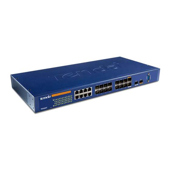
24-Port Managed Gigabit Switch Chapter 1 Product Introduction TEG3224T 24-Port Managed Gigabit Switch was designed for departmental enterprise connections. provides 10/100/1000Mbps RJ-45 ports, plus 2 Gigabit mini-GBIC (SFP) combo ports. Supporting IEEE 802.1x authentication standard and IGMP Snooping, it also supports 802.1Q VLAN, Trunk, Port Mirroring, 802.1d... -
Page 9: Layer 2 Features
24-Port Managed Gigabit Switch 1.2 Layer 2 Features Provides Store-and-forward architecture Supports up to 48Gbps backplane bandwidth Max. forwarding rate: 1488095pps per port (64 bit for each packet.) Supports 8K MAC address entries Supports jumbo frame forwarding ... -
Page 10: Management
Support remote Telnet management with up to 5 users in the same time Supports CLI (Command Line Interface) 1.4 Package Contents One TEG3224T Managed Gigabit Switch Four rubber feet, two mounting ears and eights screws One AC power cord ... -
Page 11: Installation
24-Port Managed Gigabit Switch 1.5 Installation Please follow the following instructions in avoid of incorrect installation causing device damage and security threat. Put the Switch on stable place or desktop in case of falling damage. Make sure the Switch works in the proper AC input range and matches the voltage labeled on the Switch. -
Page 12: Rack-Mountable Installation In 19-Inch Cabnit
1.5.2 Rack-mountable Installation in 19-inch Cabnit The TEG3224T can be mounted in an EIA standard-sized, 19-inch rack, which can be placed in a wiring closet with other equipment. To install, attach the mounting brackets on the Switch’s side panels (one on each side) and secure them with the screws provided. -
Page 13: Power On The Switch
ON, it indicates the power connection is OK. 1.6 External Component Description 1.6.1 Front Panel The front panel of TEG3224T consists of 24 10/100/1000Mbps RJ-45 ports, 2 Gigabit SFP combo ports, 1 RS-232 Console port and a series of LED indicators shown as below. -
Page 14: Rear Panel
24-Port Managed Gigabit Switch 1.6.2 Rear Panel The rear panel of TEG3224T contains AC power connector and one marker shown as below. Rear panel view 1.6.3 Side Panels The right side panel of the Switch contains two system fans. The left side panel has heat vents as shown below. - Page 15 24-Port Managed Gigabit Switch The LED indicators of the TEG3224T contain one Power, one SYS, 26 Link/Act (including 2 SFP indicators) and 24 10/100/1000Mbps indicators. You can see their operating situation through these LED indicators. The following chart shows the LED indicators of the Switch along with explanation of each indicator.
-
Page 16: Chapter 2 Connecting The Switch
24-Port Managed Gigabit Switch Chapter 2 Connecting the Switch 2.1 Switch to End Node Use standard Cat.5/5e Ethernet cable (UTP/STP) to connect the Switch to end nodes as described below. Switch ports will automatically adjust to the characteristics (MDI/MDI-X, speed, duplex) of the device to which is connected. -
Page 17: How To Login The Switch
LEDs for each port lights green when the link is available. 2.3 How to Login the Switch TEG3224T provides the following login ways as below. By Web-based management interface using such web browser as Netscape Navigator, Internet Explorer or firefox. More details refer to the Web Login part of the Switch Configuration section. - Page 18 24-Port Managed Gigabit Switch Figure 3-2 Create a new connection Figure 3-3 Connected port connection Figure 3-4 Com1 port configurations...
- Page 19 24-Port Managed Gigabit Switch Step3: Power on the Switch and the self-test result will be shown on the terminal device. After the self-test, enter the User Name Password (admin/admin default administrator; user/user for common users) and press Enter. The command prompt will be shown as below. Figure 3-5 Switch Configuration Interface By Telnet Step1: Select Start on your computer and click Run.
- Page 20 24-Port Managed Gigabit Switch Hint: How to configure the device via Telnet or Console port please refers to the CLI User Guide on included CO-ROM.
-
Page 21: Chapter 3 Switch Configuration
24-Port Managed Gigabit Switch Chapter 3 Switch Configuration 3.1 Web Login As TEG3224T provides Web-based management login, you can configure your computer’s IP address manually to log on to the Switch. The default seetings of the Switch are shown below. -
Page 22: Web Configuration Interface
TEG3224T’s configuration solution for every aspect in Web interface, to assist users to use and manage the Switch easily. In the Web interface of the Switch, there are 13 modules as following: System ... -
Page 23: System Configuration
3.3 System Configuration In System configuration part, there are four sub-menus: Information, IP&Time, Account. 3.3.1 System Information Configuration Please select the left meun as TEG3224T→Configuration→ System→ Information to enter the following window. The switch system information is provided here. System Contact... -
Page 24: Ip And Time Configuration
The allowed string length is 0 to 255. The allowed string content is NVT ASCII character set (32 - 126). 3.3.2 IP and Time Configuration Please select the left meun as TEG3224T→Configuration→ System →IP&Time to enter the following window: You can configure the switch-managed IP information here. The... - Page 25 24-Port Managed Gigabit Switch Configured column is used to view or change the IP configuration. The Current column is used to show the active IP configuration. DHCP Client Enable the DHCP client by checking this box. If DHCP fails and the configured IP address is zero, DHCP will retry.
-
Page 26: Account
24-Port Managed Gigabit Switch 3.3.3 Account Please select the left meun as TEG3224T→Configuration→ System→Account to enter the following window: Click “Add” to enter the System Password window as below: The page allows you to configure the system password required to access the web pages or log in from CLI. -
Page 27: Power Save Configuration
24-Port Managed Gigabit Switch 3.3.4 Power Save Configuration Please select the left meun as TEG3224T→Configuration→ System→Power Save to enter the following window: Power save is used to save the Switch’s system power consumption. When Power Save Enable is checked, the unconnected port’s power in the Switch is almost zero, which can... -
Page 28: Port Configuration
24-Port Managed Gigabit Switch 3.4 Port Configuration Please select the left meun as TEG3224T→Configuration→Port to enter the following window: This window displays current port configurations. Ports can also be configured here. Port This is the logical port number for this row. - Page 29 24-Port Managed Gigabit Switch Auto – selects the highest speed that is compatible with a link partner. 1GbpsFDX – Select the link speed as 1000Mbps Full-duplex. 100MbpsFDX – Select the link speed as 100Mbps Full-duplex. 100M bpsHDX – Select the link speed as 100Mbps Half-duplex.
-
Page 30: Aggregation Mode Configuration
In addition, trunking provides point-to-point redundancy between two devices to prevent looping. The TEG3224T supports up to 12 trunk groups with 2~16 ports in each group. Link Aggregation Topology... -
Page 31: Link Aggregation Characteristics
24-Port Managed Gigabit Switch TEG3224T treats all ports in a trunk group as single port. Data transmitted to a specific host will always be transmitted over the same port in a trunk group. This allows packets in a data stream to arrive in the same order they were sent. -
Page 32: Link Aggregation Requirement For Port Settings
24-Port Managed Gigabit Switch physical path. This allows traffic loads to be distributed across multiple communication links, and a link failure within the group causes the network traffic to be directed to the remaining links in the group. The Spanning Tree Protocol will treat a port trunking group as a single link, on the Switch level. - Page 33 Port Setting: Speed, half/full-duplex, auto-negotiation : Note TEG3224T can create up to 12 port trunking groups with 2~16 ports in each group. Port enabling 802.1x can not be the member of Trunking. Mirrored port can not be the member of Trunking.
-
Page 34: Aggregation Configuration
24-Port Managed Gigabit Switch 3.5.4 Aggregation Configuration 3.5.4.1 Static Aggregation Please select the left meun as TEG3224T→Configuration→ Aggregation →Static to enter the following window: This page is used to configure the Aggregation hash mode and the aggregation group. The aggregation hash code settings are global. - Page 35 By default, no ports belong to any aggregation group. 3.5.4.2 LACP Configuration Please select the left meun as TEG3224T→Configuration→ Aggregation →LACP to enter the following window:...
- Page 36 24-Port Managed Gigabit Switch This page allows the user to inspect the current LACP port configurations, and possibly change them as well. Port The switch port number. LACP Enabled Whether LACP is enabled on this switch port. LACP will form an aggregation when 2 or more ports are connected to the same partner.
-
Page 37: Spanning Tree Configuration
3.6.1 STP Introduction Spanning Tree Protocol is a link management protocol that provides path redundancy while preventing undesirable loops in the network. TEG3224T supports two versions of the Spanning Tree Protocol: 802.1d STP and 802.1w Rapid STP. 3.6.2 802.1d STP 1. - Page 38 24-Port Managed Gigabit Switch chosen as the root switch. All the other switches in the layer-2 topology expect to see BPDUs the root switch within the maximum age time, which defaults to 20 seconds. If the switches do not see a BPDU message from the root within this period, they assume that the root switch has failed and will begin a new election process to choose a new root switch.
- Page 39 24-Port Managed Gigabit Switch With the lowest segment accumulated path cost to the root bridge. With the lowest switch ID With the lowest priority With the physically lowest-numbered port on the switch After going through these steps for each segment, each segment will have a signal designated port that it will use to reach the root switch.
- Page 40 24-Port Managed Gigabit Switch 6. 802.1w Rapid Spanning Tree The Rapid Spanning Tree Protocol (RSTP) is an IEEE standard, 802.1w, that is interoperable with 802.1d and an extension to it. With RSTP, there are only three port states: discarding, learning and forwarding.
- Page 41 24-Port Managed Gigabit Switch 7. Edge Port The edge port is a designation used for a port that is directly connected to end stations where bridging loops cannot be created in the network. Therefore, the edge port directly transitions to the forwarding state, and skips the listening and learning stages.
-
Page 42: Spanning Tree System Configuration
The table below compares how the three protocols differ as to the port state transition. 3.6.3 Spanning Tree System Configuration Please select the left meun as TEG3224T→Configuration→ Spanning Tree→ System to enter the following window: The page allows you to configure RSTP system settings. The settings are used by all RSTP Bridge instances in the Switch. -
Page 43: Rstp Port Configuration
Max. Age ≤ 2 x (Forward Delay - 1 second) Max. Age ≥ 2 x (Hello Time + 1 second) 3.6.4 RSTP Port Configuration Please select the left meun as TEG3224T→Configuration→ Spanning Tree→ Port to enter the following window:... - Page 44 24-Port Managed Gigabit Switch This page allows the user to inspect the current RSTP port configurations, and possibly change them as well. The page contains settings for aggregations and physical ports. Port The switch port number of the logical RSTP port. RSTP Enabled Whether RSTP is enabled on this switch port.
- Page 45 24-Port Managed Gigabit Switch Priority The port priority. This can be used to control priority of ports having identical port cost. (See above). Edge Whether the port is know to connect directly to Edge devices. (no Bridges attached). The Edge flag is cleared by receipt of any BPDU's on the port.
-
Page 46: Configuration
24-Port Managed Gigabit Switch 3.7 802.1x Configuration 3.7.1 802.1x Introduction The TEG3224T provides the port-based 802.1x authentication function to improve the network security. The IEEE 802.1x standard defines a client-server-based access control and authentication protocol that restricts unauthorized clients from connecting to a LAN through publicly accessible ports. -
Page 47: Configuration
24-Port Managed Gigabit Switch 3.7.2 802.1x Configuration Please select the left meun as TEG3224T→Configuration→ 802.1x to enter the following window: The page allows you to configure the IEEE 802.1X system and port settings. The IEEE 802.1X standard defines a port-based access control procedure that prevents unauthorized access to a network by requiring users to first submit credentials for authentication. - Page 48 24-Port Managed Gigabit Switch The secret - up to 29 characters long - shared between the RADIUS Server and the Switch. Reauthentication Enabled If checked, clients are re-authenticated after the interval specified by the Reauthentication Period. Re-authentication can be used to detect if a new device is plugged into a switch port, and to detect if the authenticated clients are connected well or not.
- Page 49 24-Port Managed Gigabit Switch The port ID. It cannot be changed. Admin State Sets the authentication mode to one of the following options: Auto: Requires an 802.1X-aware client (supplicant) to be authorized by the authentication server. Clients that are not 802.1X-aware will be denied access.
- Page 50 24-Port Managed Gigabit Switch Admin State is Auto. Clicking these buttons will not cause settings changed on the page to take effect. Reauthenticate: Schedules a reauthentication to whenever the quiet-period of the port runs out. Reinitialize: Bypasses the quiet-period of the port and enables immediate reauthentication regardless of the status for the quiet-period.
-
Page 51: Igmp Snooping
24-Port Managed Gigabit Switch 3.8 IGMP Snooping 3.8.1 IGMP Snooping Introduction IGMP Snooping is the process of listening to IGMP traffic, which allows the switch to "listen in" on the IGMP conversation between hosts and routers by processing the layer 3 IGMP packets sent in a multicast network. -
Page 52: Igmp Snooping Working Mechanism
24-Port Managed Gigabit Switch 3.8.2 IGMP Snooping Working Mechanism When IGMP snooping is enabled, the multicast router sends out periodic IGMP general queries to all VLANs. The switch responds to the router queriers with only one join request per MAC multicast group, and the switch creates one entry per VLAN in the Layer 2 forwarding table for each MAC group from which it receives an IGMP join request. - Page 53 24-Port Managed Gigabit Switch ther router continues forwarding the multicast traffic to the VLAN. The switch only forwards IP multicast group traffic to those hosts listed in the forwarding table for that IP multicast group. When hosts need to leave a multicast group, they can either ignore the periodic general-query requests sent by the router, or they can send a leave message.
-
Page 54: Igmp Snooping Configuration
24-Port Managed Gigabit Switch 3.8.3 IGMP Snooping Configuration Please select the left meun as TEG3224T→Configuration→ IGMP Snooping to enter the following window: The page provides IGMP Snooping related configuration. Most of the settings are global. Snooping Enabled Enable the Global IGMP Snooping. -
Page 55: Lldp
The required transport type field in LLDP is Type Length Value (TLV). LLDP usage makes the network trouble shooting become easier, keeps high capability of network topology maintenance and searching. 3.9.2 LLDP Configuration Please select the left meun as TEG3224T→Configuration→LLDP to enter the following window:... - Page 56 24-Port Managed Gigabit Switch This page allows the user to inspect and configure the current LLDP port settings. 1. LLDP Parameters Tx Interval The switch is periodically transmitting LLDP frames to its neighbors for having the network discovery information up-to-date. The interval between each LLDP frame is determined by the Tx Interval value.
- Page 57 24-Port Managed Gigabit Switch Valid values are restricted to 1 - 10 seconds. 2. LLDP Port Configuration Port The switch port number of the logical LLDP port. Mode Select LLDP mode. Rx only The switch will not send out LLDP information, but LLDP information from neighbor units is analyzed.
-
Page 58: Mac Address Table Configuration
24-Port Managed Gigabit Switch 3.10 MAC Address Table Configuration Please select the left meun as TEG3224T→Configuration→MAC Address Table to enter the following window: The MAC Address Table is configured on this page. Set timeouts for entries in the dynamic MAC Table and configure the static MAC table here. -
Page 59: Static Mac Table Configuration
24-Port Managed Gigabit Switch Auto Learning is done automatically as soon as a frame with unknown SMAC is received. Disable No learning is done. Secure Only static MAC entries are learned, all other frames are dropped. Note : Make sure that the link used for managing the switch is added to the Static MAC Table before changing to secure learning mode, otherwise the management link is lost and can only be restored by using another non-secure port or by connecting to the switch... - Page 60 24-Port Managed Gigabit Switch The VLAN ID for the entry. MAC Address The MAC address for the entry. Port Members Checkmarks indicate which ports are members of the entry. Check or uncheck as needed to modify the entry. Adding a New Static Entry Click to add a new entry to the static MAC table.
-
Page 61: Vlan
24-Port Managed Gigabit Switch 3.11 VLAN 3.11.1 What is a VLAN? A Virtual Local Area Network (VLAN) defined in the IEEE802.1Q standard, as can be inferred from the name allows you to create a virtual LAN as which as far as the users are concerned behaves the same way as a regular LAN does. - Page 62 24-Port Managed Gigabit Switch using a shared link so that there will be much less collision. In addition, it is possible to also group a large LAN based on some logic to smaller VLANs and reduce broadcast traffic overall as each broadcast will be sent on to the relevant VLAN only.
-
Page 63: Several Types Of Vlans
IP Subnet Based VLANs- all the traffic in this type of VLAN is split according to the IP subnet of each source/destination. 3.11.4 VLAN Memberships Configuration Please select the left meun as TEG3224T→Configuration→ VLANs→ VLAN Memberships to enter the following window:... - Page 64 24-Port Managed Gigabit Switch The VLAN membership configurations for the Switch can be monitored and modified here. Up to 64 VLANs are supported. This page allows for adding and deleting VLANs as well as adding and deleting port members of each VLAN. Delete To delete a VLAN entry, check this box.
-
Page 65: Vlan Port Configuration
24-Port Managed Gigabit Switch 3.11.5 VLAN Port Configuration Please select the left meun as TEG3224T→Configuration→ VLANs→ Port to enter the following window: This page is used for configuring the switch port VLAN. Port This is the logical port number for this row. - Page 66 24-Port Managed Gigabit Switch classified VLAN of the frame, the frame is discarded. By default, ingress filtering is disabled (no checkmark). Frame Type Determine whether the port accepts all frames or only tagged frames. This parameter affects VLAN ingress processing. If the port only accepts tagged frames, untagged frames received on the port are discarded.
-
Page 67: Quality Of Sevice (Qos)
24-Port Managed Gigabit Switch 3.12 Quality of Sevice (QoS) 3.12.1 QoS Introduction QoS stands for Quality of Service. QoS is a generic name for a set of algorithms which attempt to provide different levels of quality to ensure high-quality performance for critical applications as VoIP packets. - Page 68 24-Port Managed Gigabit Switch are four additional octets inserted after the source MAC address. Their presence is indicated by a value of 0x8100 in the EtherType field. When a packet's EtherType field is equal to 0x8100, the packet carries the IEEE 802.1Q/802.1p tag (see IEEE 802.1p Priority section).
- Page 69 7 assigned to the highest. The highest priority tag 7 is generally only used for data associated with video or audio applications sensitive to even slight delays. TEG3224T allows you to further tailor how priority tagged data packets are handled on your network.
-
Page 70: Scheduling Mechanism
3.12.3 Scheduling Mechanism When the network traffic is congestive, usually scheduling mechanism is deployed to solve the traffic order. TEG3224T supports two ways: SP (Strict-Priority) and WFQ (Weighted Fair Queuing). This part allows you to select WFQ or Strict scheduling mechanism for emptying the priority classes. -
Page 71: Qos Configuration
24-Port Managed Gigabit Switch 3.12.4 QoS Configuration 3.12.4.1 QCL Configuration Wizard Please select the left meun as TEG3224T→Configuration→ QoS→ Wizard to enter the following window: This handy wizard helps you set up a QCL quickly in void of complicate settings. The wizard consists of: Set up Port Policies:... - Page 72 24-Port Managed Gigabit Switch Audio and Video Indicates the common servers that apply to the specific QCE. The common servers are: QuickTime 4 Server, MSN Messenger Phone, Yahoo Messenger Phone, Napster, Real Audio. Games Indicates the common games that apply to the specific QCE. User Definition Indicates the user definition that applies to the specific QCE.
- Page 73 Select a traffic class of Low, Normal, Medium, or High to apply to the QCE. 3.12.4.2 Port QoS Configuration Please select the left meun as TEG3224T→Configuration→ QoS→Port to enter the following window: This page allows you to configure QoS settings for each port.
- Page 74 24-Port Managed Gigabit Switch QCEs. Each QCE can be used to classify certain frames to a specific QoS class. This classification can be based on parameters such as VLAN ID, UDP/TCP port, IPv4/IPv6 DSCP or Tag Priority. Frames not matching any of the QCEs are classified to the default QoS class for the port.
- Page 75 24-Port Managed Gigabit Switch 3.12.4.3 QoS Control List Configuration Please select the left meun as TEG3224T→Configuration→ QoS→QoS Control List to enter the following window: QCL # Select a QCL to display a table that lists all the QCEs for that particular QCL.
- Page 76 24-Port Managed Gigabit Switch tagged or priority tagged. Type Value Indicates the value according to its QCE type. Ethernet Type: The field shows the Ethernet Type value. VLAN ID: The field shows the VLAN ID. TCP/UDP Port: The field shows the TCP/UDP port range. DSCP: The field shows the IPv4/IPv6 DSCP value.
- Page 77 24-Port Managed Gigabit Switch 3.12.4.4 Rate Limit Configuration Please select the left meun as TEG3224T→Configuration→ QoS→Rate Limiters to enter the following window: Configure the switch port rate limit for Policers and Shapers on this page. Port The logical port for the settings contained in the same row.
- Page 78 Configure the unit of measure for the port shaper rate as kbps or Mbps. The default value is "kbps". 3.12.4.5 Storm Control Configuration Please select the left meun as TEG3224T→Configuration→ QoS→Storm Control to enter the following window: Storm control for the switch is configured on this page. There is a unicast storm rate control, multicast storm rate control, and a broadcast storm rate control.
- Page 79 24-Port Managed Gigabit Switch less than 15, or "No Limit". The unit of the rate can be either pps (packets per second) or kpps (kilopackets per second). The configuration indicates the permitted packet rate for unicast, multicast, or broadcast traffic across the switch. Frame Type The settings in a particular row apply to the frame type listed here: unicast, multicast, or broadcast.
-
Page 80: Access Control List (Acl)
MAC address, source MAC address, destination IP address, source IP address, protocol and port number and so on. 3.13.2 ACL Configuration 3.13.2.1. ACL Configuration Please select the left meun as TEG3224T→Configuration→ ACL→ Wizard to enter the following window:... - Page 81 24-Port Managed Gigabit Switch This handy wizard helps you set up an ACL quickly. Set up Policy Rules Set up the default policy rules for Client ports, Server ports, Network ports and Guest ports. Select “Next” to enter the following window: In this window set up the default policy rules for Client ports, Server ports, Network ports, and Guest ports.
- Page 82 24-Port Managed Gigabit Switch flooding and ICMP flooding. Policy 5 for guest ports: Internet access only. Set up Port Policies Group ports into several types according to different ACL policies. Click “Next” to enter the following window: Policy ID Frames that hit this ACE are set to match this specific policy. Port Members A row of radio buttons for each port is displayed for each Policy ID.
- Page 83 24-Port Managed Gigabit Switch Common Servers Indicates the common servers that applies to the specific ACE. The common servers are: DHCP, DNS, FTP, HTTP, IMAP, NFS, POP3, SAMBA, SMTP, TELNET, TFTP. Instant Messaging Indicates the instant messaging service that applies to the specific ACE.
- Page 84 24-Port Managed Gigabit Switch Click “Next” to enter the next window: According to your decision on the previous page, this wizard will create specific ACEs (Access Control Entries) automatically. First select the ingress port for the ACEs, and then select the action, rate limiter ID, logging and shutdown.
- Page 85 24-Port Managed Gigabit Switch Specify the action to take with a frame that hits this ACE. Permit: The frame that hits this ACE is granted permission for the ACE operation. Deny: The frame that hits this ACE is dropped. Rate Limiter Specify the rate limiter in number of base units.
- Page 86 24-Port Managed Gigabit Switch Port The logical port for the settings contained in the same row. Binding Enabled Enable or disable the source IP and source MAC binding status for the given logical port. Source MAC Address The source MAC address for the source IP and source MAC binding.
- Page 87 24-Port Managed Gigabit Switch UDP DoS - Fraggle A malicious attacker sending a large number of UDP packets with random ports to the target system. When the target system receives these packets, it will determine what application is waiting on the destination port. When it realizes that there is no application that is waiting on the port, it will generate an ICMP packet of destination unreachable to the spoofed source address.
- Page 88 24-Port Managed Gigabit Switch generated. Click “Next”, to enter the next window: According to your decision on the previous page, this wizard will create specific ACEs (Access Control Entries) automatically. First select the ingress port for the ACEs, and then select the action, rate limiter ID, logging and shutdown.
- Page 89 Enabled: If a frame matches the ACE, the ingress port will be disabled. Disabled: Port shut down is disabled for the ACE. 3.13.2.2 ACL Ports Configuration Please select the left meun as TEG3224T→Configuration→ ACL→Port to enter the following window:...
- Page 90 24-Port Managed Gigabit Switch Configure the ACL parameters (ACE) of each switch port. These parameters will affect frames received on a port unless the frame matches a specific ACE. Port The logical port for the settings contained in the same row. Policy ID Select the policy to apply to this port.
- Page 91 Port shut down is disabled. The default value is "Disabled". Counter Counts the number of frames that match this ACE. 3.13.2.3 ACL Rate Limiter Configuration Please select the left meun as TEG3224T→Configuration→ ACL→Tate Limiters to enter the following window:...
- Page 92 2, 4, 8, 16, 32, 64, 128, 256, 512, 1K, 2K, 4K, 8K, 16K, 32K, 64K, 128K, 256K, 512K, or 1024K. The 1 kpps is actually 1002.1 pps. 3.13.2.4 ACL Access Control List Configuration Please select the left meun as TEG3224T→Configuration→ ACL→ Access Control List to enter the following window:...
- Page 93 24-Port Managed Gigabit Switch This page shows the Access Control List (ACL), which is made up of the ACEs defined for this switch. Each row describes the ACE that is defined. The maximum number of ACEs is 128. Click on the lowest plus sign to add a new ACE to the list.
- Page 94 24-Port Managed Gigabit Switch ICMP/UDP/TCP. Action Indicates the forwarding action of the ACE. Permit: Frames matching the ACE may be forwarded and learned. Deny: Frames matching the ACE are dropped. Rate Limiter Indicates the rate limiter number of the ACE. The allowed range is 1 to 15.
- Page 95 24-Port Managed Gigabit Switch Disabled: Port shut down is disabled for the ACE. Counter The counter indicates the number of times the ACE was hit by a frame. Modification Buttons You can modify each ACE (Access Control Entry) in the table using the following buttons: “+”: Inserts a new ACE before the current row.
- Page 96 24-Port Managed Gigabit Switch frame that hits this ACE matches the configuration that is defined here. Ingress Port Select the ingress port for which this ACE applies. Any: The ACE applies to any port. Port n: The ACE applies to this port number, where n is the number of the switch port.
- Page 97 24-Port Managed Gigabit Switch Rate Limiter Specify the rate limiter in number of base units. The allowed range is 1 to 15. Disabled indicates that the rate limiter operation is disabled. Port Copy Frames that hit the ACE are copied to the port number specified here.
- Page 98 24-Port Managed Gigabit Switch SMAC Filter (Only displayed when the frame type is Ethernet Type or ARP.) Specify the source MAC filter for this ACE. Any: No SMAC filter is specified. (SMAC filter status is "don't-care".) Specific: If you want to filter a specific source MAC address with this ACE, choose this value.
- Page 99 24-Port Managed Gigabit Switch "xx-xx-xx-xx-xx-xx". A frame that hits this ACE matches this DMAC value. VLAN Parameters VLAN ID Filter Specify the VLAN ID filter for this ACE. Any: No VLAN ID filter is specified. (VLAN ID filter status is "don't-care".) Specific: If you want to filter a specific VLAN ID with this ACE, choose this value.
- Page 100 24-Port Managed Gigabit Switch ARP/RARP Specify the available ARP/RARP opcode (OP) flag for this ACE. Any: No ARP/RARP OP flag is specified. (OP is "don't-care".) ARP: Frame must have ARP/RARP opcode set to ARP. RARP: Frame must have ARP/RARP opcode set to RARP. Other: Frame has unknown ARP/RARP Opcode flag.
- Page 101 24-Port Managed Gigabit Switch Target IP Filter Specify the target IP filter for this specific ACE. Any: No target IP filter is specified. (Target IP filter is "don't-care".) Host: Target IP filter is set to Host. Specify the target IP address in the Target IP Address field that appears.
- Page 102 24-Port Managed Gigabit Switch IP/Ethernet Length Specify whether frames can hit the action according to their ARP/RARP hardware address length (HLN) and protocol address length (PLN) settings. 0: ARP/RARP frames where the HLN is equal to Ethernet (0x06) and the (PLN) is equal to IPv4 (0x04) must not match this entry.
- Page 103 24-Port Managed Gigabit Switch IP Parameters The IP parameters can be configured when Frame Type "IPv4" is selected. IP Protocol Filter Specify the IP protocol filter for this ACE. Any: No IP protocol filter is specified ("don't-care"). Specific: If you want to filter a specific IP protocol filter with this ACE, choose this value.
- Page 104 24-Port Managed Gigabit Switch non-zero: IPv4 frames with a Time-to-Live field greater than zero must be able to match this entry. Any value is allowed ("don't-care"). IP Fragment Specify the fragment offset settings for this ACE. This involves the settings for the More Fragments (MF) bit and the Fragment Offset (FRAG OFFSET) field for an IPv4 frame.
- Page 105 24-Port Managed Gigabit Switch Network Source IP filter is set to Network. Specify the source IP address and source IP mask in the SIP Address and SIP Mask fields that appear. SIP Address When "Host" or "Network" is selected for the source IP filter, you can enter a specific SIP address in dotted decimal notation.
- Page 106 24-Port Managed Gigabit Switch ICMP Type Filter Specify the ICMP filter for this ACE. No ICMP filter is specified (ICMP filter status is "don't-care"). Specific If you want to filter a specific ICMP filter with this ACE, you can enter a specific ICMP value. A field for entering an ICMP value appears.
- Page 107 24-Port Managed Gigabit Switch Specific If you want to filter a specific TCP/UDP source filter with this ACE, you can enter a specific TCP/UDP source value. A field for entering a TCP/UDP source value appears. Range If you want to filter a specific TCP/UDP source range filter with this ACE, you can enter a specific TCP/UDP source range value.
- Page 108 24-Port Managed Gigabit Switch TCP/UDP destination range value. A field for entering a TCP/UDP destination value appears. TCP/UDP Destination Number When "Specific" is selected for the TCP/UDP destination filter, you can enter a specific TCP/UDP destination value. The allowed range is 0 to 65535. A frame that hits this ACE matches this TCP/UDP destination value.
- Page 109 24-Port Managed Gigabit Switch Any value is allowed ("don't-care"). TCP PSH Specify the TCP "Push Function" (PSH) value for this ACE. TCP frames where the PSH field is set must not be able to match this entry. TCP frames where the PSH field is set must be able to match this entry.
- Page 110 24-Port Managed Gigabit Switch EtherType Filter Specify the Ethernet type filter for this ACE. No EtherType filter is specified (EtherType filter status is "don't-care"). Specific If you want to filter a specific EtherType filter with this ACE, you can enter a specific EtherType value. A field for entering a EtherType value appears.
-
Page 111: Port Mirroring
TEG3224T allows the users to configure port mirroring by assigning the target port from which to copy all packets and source port where those packets will be sent. -
Page 112: Mirroring Configuration
24-Port Managed Gigabit Switch 3.14.2 Mirroring Configuration Please select the left meun as TEG3224T→Configuration→ Mirroring to enter the following window: Configure port Mirroring on this page. To debug network problems, selected traffic can be copied, or mirrored, to a mirror port where a frame analyzer can be attached to analyze the frame flow. - Page 113 24-Port Managed Gigabit Switch Mirroring Port Configuration The following table is used for Rx and Tx enabling. Port The logical port for the settings contained in the same row. Mode Select mirror mode. Rx only Frames received at this port are mirrored to the mirroring port.
-
Page 114: Simple Network Management Protocol (Snmp)
MIB specifications and the protocol used to access this information over the network. 3.15.2 SNMP Configuration TEG3224T supports SNMP v1 and SNMP v2c. Please select the left meun as TEG3224T→Configuration→SNMP to enter the following window:... - Page 115 24-Port Managed Gigabit Switch In this window, it is used to configure SNMP setting. It can be divided into two parts: SNMP Configuration Mode Indicates the SNMP mode operation. Possible modes are: Enabled: Enable SNMP mode operation. Disabled: Disable SNMP mode operation. Version Indicates the SNMP supported version.
- Page 116 24-Port Managed Gigabit Switch allowed string content is NVT ASCII character set (32 - 126) except for spaces. SNMP Trap Configuration Trap Mode Indicates the SNMP trap mode operation. Possible modes are: Enabled: Enable SNMP trap mode operation. Disabled: Disable SNMP trap mode operation. Trap Version Indicates the SNMP trap supported version.
-
Page 117: Chapter 4 Switch's Monitor
24-Port Managed Gigabit Switch Chapter 4 Switch’s Monitor 4.1 System 4.1.1 Information Please select the left meun as TEG3224T→Monitor→System→ Information to enter the following window: The switch system information is provided here. Contact The system contact configured in Configuration | System | Information | System Contact. -
Page 118: System Log
Software Date The date when the switch software was produced. 4.1.2 System Log Please select the left meun as TEG3224T→Monitor→System →Log to enter the following window: The switch system log information is provided here. The ID (>= 1) of the system log entry. -
Page 119: Detailed Log
Message The message of the system log entry. 4.1.3 Detailed Log Please select the left meun as TEG3224T→Monitor→System →Detailed Log to enter the following window: The switch system detailed log information is provided here. The ID (>= 1) of the system log entry. -
Page 120: Ports
24-Port Managed Gigabit Switch 4.2 Ports 4.2.1 Traffic Overview Please select the left meun as TEG3224T→Monitor→Port→ Traffic Overview to enter the following window: The page provides an overview of general traffic statistics for all switch ports. The displayed counters are: Port The logical port for the settings contained in the same row. -
Page 121: Qos Statictics
24-Port Managed Gigabit Switch The number of received frames filtered by the forwarding process. 4.2.2 QoS Statictics Please select the left meun as TEG3224T→Monitor→Port→QoS Statistics to enter the following window: The page provides statistics for the different queues for all switch ports. -
Page 122: Port Statistics
Receive/Transmit The number of received and transmitted packets per port. 4.2.3 Port Statistics Please select the left meun as TEG3224T→Monitor→Port→ Detailed Statistics to enter the following window: This page provides detailed traffic statistics for a specific switch port. Use the port select box to select which switch port details to display. - Page 123 24-Port Managed Gigabit Switch The number of received and transmitted (good and bad) unicast packets. Rx and Tx Multicast The number of received and transmitted (good and bad) multicast packets. Rx and Tx Broadcast The number of received and transmitted (good and bad) broadcast packets.
- Page 124 24-Port Managed Gigabit Switch The number of long frames received with valid CRC. Rx Fragments The number of short frames received with invalid CRC. Rx Jabber The number of long frames received with invalid CRC. Rx Filtered The number of received frames filtered by the forwarding process.
-
Page 125: Lacp
24-Port Managed Gigabit Switch 4.3 LACP 4.3.1 LACP System Status Please select the left meun as TEG3224T→Monitor→LACP→ System Status to enter the following window: The page provides a status overview for all LACP instances. Aggr ID The Aggregation ID associated with this aggregation instance. -
Page 126: Lacp Port Stauts
24-Port Managed Gigabit Switch 4.3.2 LACP Port Stauts Please select the left meun as TEG3224T→Monitor→LACP→Port Status to enter the following window: The page provides a status overview for LACP status for all ports. Port The switch port number. LACP 'Yes' means that LACP is enabled and the port link is up. 'No' means that LACP is not enabled or that the port link is down. -
Page 127: Lacp Statistics
24-Port Managed Gigabit Switch 4.3.3 LACP Statistics Please select the left meun as TEG3224T→Monitor→LACP→Port Statistics to enter the following window: The page provides an overview for LACP statistics for all ports. Port The switch port number. LACP Transmitted Shows how many LACP frames have been sent from each port. -
Page 128: Spanning Tree
24-Port Managed Gigabit Switch 4.4 Spanning Tree 4.4.1 Bridge Status Please select the left meun as TEG3224T→Monitor→Spanning Tree →Bridge Status to enter the following window: The page provides a status overview for all RSTP bridge instances. The displayed table contains a row for each RSTP bridge instance,... -
Page 129: Rstp Port Status
The current state of the Topology Change Flag for this Bridge instance. 4.4.2 RSTP Port Status Please select the left meun as TEG3224T→Monitor→Spanning Tree →Port Status to enter the following window: The page displays the RSTP port status for port physical ports in the currently selected switch. -
Page 130: Rstp Statistics
The RSTP Bridge instance (VLAN ID). This is also a link to the RSTP Detailed Bridge Status, if the port is RSTP enabled. 4.4.3 RSTP Statistics Please select the left meun as TEG3224T→Monitor→Spanning Tree→ Port Statistics to enter the following window: The page displays the RSTP port statistics counters for port physical ports in the currently selected switch. - Page 131 24-Port Managed Gigabit Switch RSTP The number of RSTP Configuration BPDU's received/transmitted on the port. The number of legacy STP Configuration BPDU's received/transmitted on the port. The number of (legacy) Topology Change Notification BPDU's received/transmitted on the port. Discarded Unknown The number of unknown Spanning Tree BPDU's received (and discarded) on the port.
-
Page 132: 125
24-Port Managed Gigabit Switch 4.5 802.1x 4.5.1 Port Status Please select the left meun as TEG3224T→Monitor→802.1x→ Port Status to enter the following window: The page provides an overview of the current IEEE 802.1X port states for the selected switch. Port The switch port number. -
Page 133: Port Statistics
24-Port Managed Gigabit Switch 4.5.2 802.1x Port Statistics Please select the left meun as TEG3224T→Monitor→802.1x→ Port Statistics to enter the following window: The page provides detailed IEEE 802.1X statistics for a specific switch port. Use the port select box to select which port details to display. - Page 134 24-Port Managed Gigabit Switch received by the switch. dot1xAuth The number of EAPOL Start frames Start EapolStart that have been received by the FramesRx switch. dot1xAuth The number of valid EAPOL logoff Logoff EapolLogoff frames that have been received by FramesRx the switch.
- Page 135 24-Port Managed Gigabit Switch RADIUS Counters Direction Name IEEE Name Description Counts the number of times that the dot1xAuth switch receives the first request from Access Backend the RADIUS server following the first Challenges Access response from supplicant. Challenges Indicates that the RADIUS server has communication with the switch.
-
Page 136: Igmp Snooping
EAPOL frame. The user name (supplicant identity) carried in the most recently received Identity Resp/ID EAPOL frame. 4.6 IGMP Snooping Please select the left meun as TEG3224T→Monitor→IGMP to enter the following window: The page provides IGMP Snooping status. - Page 137 24-Port Managed Gigabit Switch VLAN ID The VLAN ID of the entry. Groups The present IGMP groups. Max. are 128 groups for each VLAN. Port Members The ports that are members of the entry. Querier Status Show the Querier status is "ACTIVE" or "IDLE". Querier Transmit The number of Transmitted Querier.
-
Page 138: Lldp
24-Port Managed Gigabit Switch 4.7 LLDP 4.7.1 LLDP Neighbours Please select the left meun as TEG3224T→Monitor→LLDP→ Nerghbors to enter the following window: The page provides a status overview for all LLDP neighbors. The displayed table contains a row for each port on which an LLDP neighbor is detected. -
Page 139: Lldp Port Statistics
This could for instance hold the neighbor's IP address. 4.7.2 LLDP Port Statistics Please select the left meun as TEG3224T→Monitor→LLDP→Port statistics to enter the following window: The page provides an overview of all LLDP traffic. The displayed... - Page 140 24-Port Managed Gigabit Switch table contains a row for each port. The columns hold the following information: Local Port The port on which LLDP frames are received or transmitted. Tx Frames The number of LLDP frames transmitted on the port. Rx Frames The number of LLDP frames received on the port.
-
Page 141: Mac Address Table
Age-Out counter is incremented. 4.8 MAC Address Table Please select the left meun as TEG3224T→Monitor→MAC Address Table to enter the following window: Entries in the MAC Table are shown on this page. The MAC Table contains up to 8192 entries, and is sorted first by VLAN ID, then by MAC address. - Page 142 24-Port Managed Gigabit Switch beginning of the MAC Table. The first displayed will be the one with the lowest VLAN ID and the lowest MAC address found in the MAC Table. The "Start from MAC address" and "VLAN" input fields allow the user to select the starting point in the MAC Table.
-
Page 143: Chapter 5 Switch's Diagnostics
24-Port Managed Gigabit Switch Chapter 5 Switch’s Diagnostics 5.1 ICMP Ping Please select the left meun as TEG3224T→Diagnostics→Ping to enter the following window: The page allows you to issue ICMP PING packets to troubleshoot IP connectivity issues. After you press Start button, 5 ICMP packets are transmitted, and the sequence number and roundtrip time are displayed upon reception of a reply. -
Page 144: Veriphy
24-Port Managed Gigabit Switch 5.2 VeriPHY Please select the left meun as TEG3224T→Diagnostics→ VeriPHY to enter the following window: The page is used for running the VeriPHY Cable Diagnostics. Press to run the diagnostics. This will take approximately 5 seconds. If all ports are selected, this can take approximately 15 seconds. -
Page 145: Chapter 6 Switch's Maintenance
24-Port Managed Gigabit Switch Chapter 6 Switch’s Maintenance 6.1 System Reboot Please select the left meun as TEG3224T→Maintenance→ Reboot Device to enter the following window: You can reboot the Switch on this page. After rebooting, the system will boot normally as if you power on the devices. -
Page 146: Firmware Update
No: Click to return to the System Information page without resetting system configuration. 6.3 Firmware Update Please select the left meun as TEG3224T→Maintenance→ Software Upload to enter the following window: This page facilitates an update of the firmware in the Switch. -
Page 147: Settings Upload
6.4 Settings Upload Please select the left meun as TEG3224T→Maintenance→ Settings Upload to enter the following window: This page facilitates uploading settings to the Switch. Click “Browse”... -
Page 148: Syslog Download
No: Click to return to the System Information page without proceeding downloading. 6.6 Syslog Download Please select the left meun as TEG3224T→Maintenance→Syslog Download to enter the following window: You can download the Switch’s syslog to your computer on this page. -
Page 149: Chapter 7 Appendix
24-Port Managed Gigabit Switch Chapter 7 Appendix 7.1 Product Specification General Feature IEEE 802.3 10BASE-T Ethernet IEEE 802.3u 100BASE-TX Fast Ethernet IEEE 802.3z 1000BASE-SX Gigabit Ethernet IEEE 802.3z 1000BASE-LX Gigabit Ethernet IEEE 802.3ab 1000BASE-T Gigabit Ethernet IEEE 802.1d Spanning Tree IEEE 802.1w Rapid Spanning Tree Standard IEEE 802.1Q VLAN... - Page 150 24-Port Managed Gigabit Switch IEEE 802.3z WDM 1000BASE-LX IEEE 802.3z WDM 1000BASE-LHX Network Cables 10Base-T:Cat. 3 or 3e UTP (100m) Network Cables 100Base-TX:Cat. 5 UTP (100m) 1000Base-T:Cat. 5 or 5e UTP (100m) 1000Base-LX:SMF(10km) 1000Base-SX:MMF(550m) Fiber 1000Base-LHX:SMF(50km) 1000Base-ZX:SMF(80km) Performance Forwarding Method Store-and-forward MAC Address Entry 14880pps(10Mbps line-speed)...
-
Page 151: Glossary
24-Port Managed Gigabit Switch 7.2 Glossary ACE is an acronym for Access Control Entry. It describes access permission associated with a particular ACE ID. There are three ACE frame types (Ethernet Type, ARP, and IPv4) and two ACE actions (permit and deny). The ACE also contains many detailed, different parameter options that are available for individual application. - Page 152 24-Port Managed Gigabit Switch beyond the limits of a port and to increase the redundancy for higher availability. (Also Port Aggregation, Link Aggregation). ARP is an acronym for Address Resolution Protocol. It is a protocol that used to convert an IP address into a physical address, such as an Ethernet address.
- Page 153 24-Port Managed Gigabit Switch first client's assignment is valid (its lease has not expired). Therefore, IP address pool management is done by the server and not by a human network administrator. Dynamic addressing simplifies network administration because the software keeps track of IP addresses rather than requiring an administrator to manage the task.
- Page 154 24-Port Managed Gigabit Switch between octets. An IPv4 dotted decimal address has the form x.y.z.w, where x, y, z, and w are decimal numbers between 0 and 255. DSCP DSCP is an acronym for Differentiated Services Code Point. It is a field in the header of IP packets for packet classification purposes.
- Page 155 24-Port Managed Gigabit Switch response to various commands. For example, when you enter a URL in your browser, this actually sends an HTTP command to the Web server directing it to fetch and transmit the requested Web page. The other main standard that controls how the World Wide Web works is HTML, which covers how Web pages are formatted and displayed.
- Page 156 24-Port Managed Gigabit Switch considered an adequate degree of encryption for commercial exchange. ICMP ICMP is an acronym for Internet Control Message Protocol. It is a protocol that generated the error response, diagnostic or routing purposes. ICMP messages generally contain information about routing difficulties or simple exchanges such as time-stamp or echo transactions.
- Page 157 24-Port Managed Gigabit Switch more efficient use of resources when supporting these uses. IGMP Querier A router sends IGMP Query messages onto a particular link. This router is called the Querier. IMAP IMAP is an acronym for Internet Message Access Protocol. It is a protocol for email clients to retrieve email messages from a mail server.
- Page 158 24-Port Managed Gigabit Switch Area Network (LAN) or Wide Area Network (WAN) is given an Internet Protocol address, and this IP address is used to identify the device uniquely among all other devices connected to the extended network. The current version of the Internet protocol is IPv4, which has 32-bits Internet Protocol addresses allowing for in excess of four billion unique addresses.
- Page 159 24-Port Managed Gigabit Switch MAC Table Switching of frames is based upon the DMAC address contained in the frame. The switch builds up a table that maps MAC addresses to switch ports for knowing which ports the frames should go to ( based upon the DMAC address in the frame ).
- Page 160 24-Port Managed Gigabit Switch to communicate within a Local Area Network (LAN), and it is not supported on a Wide Area Network (WAN). The NetBIOS giving each computer in the network both a NetBIOS name and an IP address corresponding to a different host name, provides the session and transport services described in the Open Systems Interconnection (OSI) model.
- Page 161 24-Port Managed Gigabit Switch Policer A policer can limit the bandwidth of received frames. It is located in front of the ingress queue. POP3 POP3 is an acronym for Post Office Protocol version 3. It is a protocol for email clients to retrieve email messages from a mail server.
- Page 162 24-Port Managed Gigabit Switch There are six QCE frame types: Ethernet Type, VLAN, UDP/TCP Port, DSCP, TOS, and Tag Priority. Frames can be classified by one of 4 different QoS classes: "Low", "Normal", "Medium", and "High" for individual application. QCL is an acronym for QoS Control List. It is the list table of QCEs, containing QoS control entries that classify to a specific QoS class on specific traffic objects.
- Page 163 24-Port Managed Gigabit Switch It is a protocol that is used to obtain an IP address for a given hardware address, such as an Ethernet address. RARP is the complement of ARP. Router Port A router port is a port on the Ethernet switch that leads switch towards the Layer 3 multicast device.
- Page 164 24-Port Managed Gigabit Switch network so that it would appear in the listing of hosts in Microsoft Windows "Neighborhood Network". Shaper A shaper can limit the bandwidth of transmitted frames. It is located after the ingress queues. SMTP SMTP is an acronym for Simple Mail Transfer Protocol. It is a text-based protocol that uses the Transmission Control Protocol (TCP) and provides a mail service modeled on the FTP file transfer service.
- Page 165 24-Port Managed Gigabit Switch STP protocol is now obsoleted by RSTP. Tag Priority Tag Priority is a 3-bit field storing the priority level for the 802.1Q frame. TCP is an acronym for Transmission Control Protocol. It is a communications protocol that uses the Internet Protocol (IP) to exchange the messages between computers.
- Page 166 24-Port Managed Gigabit Switch (TCP) and provides a virtual connection between TELNET server and TELNET client. TELNET enables the client to control the server and communicate with other servers on the network. To start a Telnet session, the client user must log in to a server by entering a valid username and password.
- Page 167 24-Port Managed Gigabit Switch (TCP) that uses the Internet Protocol (IP). Unlike TCP, UDP does not provide the service of dividing a message into packet datagrams, and UDP doesn't provide reassembling and sequencing of the packets. This means that the application program that uses UDP must be able to make sure that the entire message has arrived and is in the right order.
- Page 168 24-Port Managed Gigabit Switch VLAN 1, and the switch does not remove or insert VLAN tags. VLAN aware switching: This is based on the IEEE 802.1Q standard. All ports are VLAN aware. Ports connected to VLAN aware switches are members of multiple VLANs and transmit tagged frames.
-
Page 169: Online Technical Support
24-Port Managed Gigabit Switch 7.3 Online Technical Support For any problem occurring during the installation, log in to www.tenda. cn for help. The downloading center of the technical support part provides the latest driver and upgrade package for downloading. -
Page 170: Common Commands
24-Port Managed Gigabit Switch 7.4 Common Commands Common Description Commands Quickly entering the command line mode of Windows system (applicable to Windows2000 and higher). Displaying the IP address of the current computer, for example, ipconfig ipconfig /all. It is most frequently used in the network test. It is used to send a packet to the target host, asking for response. -
Page 171: Tcp/Ip Address Setting (Windows Xp As Example)
24-Port Managed Gigabit Switch 7.5 TCP/IP Address Setting (Windows XP as Example) Select “Start → Control Panel” to display the “Control Panel” window (see Figure 1). Figure 1 Click “Network Connection” to display the “Network Connections” window (see Figure 2). Figure 2 Right-click “Local Area Connection”... - Page 172 24-Port Managed Gigabit Switch connection uses the following items”, and then click “Properties” (see Figure 3). Figure 3 In “Use the following IP address”, enter “192.168.0.xxx” (“xxx” ranges 2 ~ 254) for IP address and 255.255.255.0 for subnet mask (see Figure 4). Figure 4 Click “OK”...
- Page 173 24-Port Managed Gigabit Switch...
Need help?
Do you have a question about the TEG3224T and is the answer not in the manual?
Questions and answers