Table of Contents
Advertisement
Quick Links
INSTALLATION AND OPERATING INSTRUCTIONS FOR AUTOMATIC
INSTANTANEOUS TYPE WATER HEATERS FOR USE WITH NATURAL AND
LIQUEFIED PETROLEUM GAS
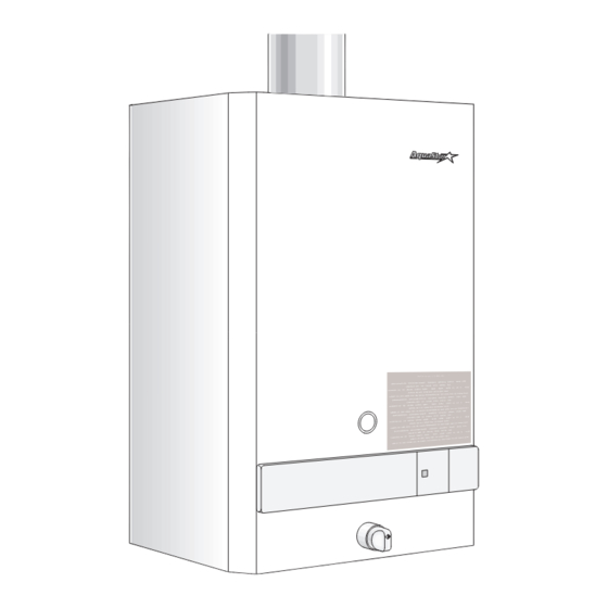
MODEL 125X LP and 125X NG (Flow Modulated with Electronic Ignition)
Suitable for water (potable) heating and space heating
Intended for variable flow applications with steady cold water inlet temperatures.
WARNING
: Improper installation, adjustment,
alteration, service or maintenance can cause injury
or property damage. Refer to this manual. For
assistance or additional information consult a
qualified installer, service agency or the gas supplier.
Upon completion of the installation, these instructions
should be handed to the user of the appliance for
future reference.
FEATURING: Automatic Variable Power Modulating Gas
Valve and Electronic Ignition
For preheated domestic hot water, install the 125 BS model.
WARNING
If the information in this manual is not followed exactly,
a fire or explosion may result causing property
damage, personal injury or death.
FOR YOUR SAFETY
Do not store or use gasoline or other flammable,
combustible or corrosive vapors and liquids in the
vicinity of this or any other appliance.
WHAT TO DO IF YOU SMELL GAS
- Do not try to light any appliance.
- Do not touch any electrical switch; do not use any
phone in your building.
- Immediately call your gas supplier from a neighbor's
phone. Follow the gas supplier's instructions.
- If you cannot reach your gas supplier, call the fire
department.
- Installation and service must be performed by a
qualified installer, service agency or the gas supplier.
TABLE OF CONTENTS
Specifications .................................................... Page 2
Rules for safe operation .................................... Page 4
Locating the Heater ........................................... Page 5
Combustion Air Requirements ........................... Page 5
Mounting the Heater .......................................... Page 6
Venting the Heater ............................................. Page 6
Gas Connections ............................................... Page 7
Water Connections ............................................ Page 8
Safety before turning on the heater ................... Page 8
Operating instructions ........................................ Page 9
Setting water temperature ................................. Page 9
Trouble Shooting ............................................. Page 10
Microswitch Adjustment ................................... Page 11
Electrical Diagram ........................................... Page 12
Diagram of AquaStar ....................................... Page 13
Interior components diagram ........................... Page 14
Parts List ......................................................... Page 15
Advertisement
Table of Contents

Subscribe to Our Youtube Channel
Related Manuals for AquaStar 125X LP


Summary of Contents for AquaStar 125X LP
-
Page 1: Table Of Contents
INSTANTANEOUS TYPE WATER HEATERS FOR USE WITH NATURAL AND LIQUEFIED PETROLEUM GAS MODEL 125X LP and 125X NG (Flow Modulated with Electronic Ignition) Suitable for water (potable) heating and space heating Intended for variable flow applications with steady cold water inlet temperatures. -
Page 2: Specifications
Principle of Operation: AquaStar 125X LP and 125X NG Specifications When a hot water faucet is opened, the water flow through the heater causes the gas valve to open. At the same time a microswitch is activated which sends a spark to the Gas Input max.: 117,000 Btu/hr... - Page 3 NON COMBUSTIBLE MATERIALS FOR ALCOVE INSTALLATIONS MODEL 125B / 125B LOW PRESSURE / 125B SOLAR / 125 X TOP (A) 12" FRONT (B) OPEN BACK 0" SIDES 4" FLOOR (C) 12" FLUE DIAMETER 5" AQUASTAR MODELS 125B / 125BL / 125BS / 125X...
- Page 4 If you are using the AquaStar for combined space heating and potable water heating (see schematic diagram below) , all piping and other components connected to the system must be suitable for potable water, (b) toxic chemicals such as those commonly used for boiler...
-
Page 5: Combustion Air Requirements
Confirm that your Aquastar is venting occupied rooms normally kept closed. See the section properly when all these other appliances are running. See below on locating the heater. section on venting. - Page 6 WARNING Note: The burners of an instantaneous “on demand” water heater such as the AquaStar are only on at the time that hot water is actually being used, the venting stack is WALL STUDS therefore cold except for the short durations when hot water is being used, it is therefore very important that the venting 13 ¼”...
-
Page 7: Gas Connections
The flue connection for the AquaStar 125X is 5 inches. (660 meters) above sea level. On appliances being However, in Canada, for installations at high altitude (2000- installed above 2000 ft (660 meters) elevation, the inlet 4500 feet above sea level) a six inch flue is required. A 5"... -
Page 8: Water Connections
Blow out or flush the lines before connecting to the Open the cold water inlet supply to the heater fully. AquaStar. A ball valve should be installed on the cold water Open a hot water faucet to permit the water to fill the heater feed line to facilitate servicing the heater. -
Page 9: Setting Water Temperature
You cannot the water heater is ready to use. run out of hot water with an AquaStar, so set the dial for 5. If the red LED indicator light (visible through the the temperature you prefer . -
Page 10: Maintenance & Service
Controlled Energy for instructions. TROUBLE SHOOTING Introduction The AquaStar 125X burners are activated by a water flow valve. Numerous water related problems can cause this water valve to malfunction such as: Insufficient water flow volume to activate the burners at its minimum flow requirement;... - Page 11 TURNED ON, BUT PILOT AND BURNERS WILL NOT To confirm there is no cross-over in the plumbing, shut off IGNITE the cold water supply to the AquaStar water heater and open a hot water faucet. There should not be any water 1. Air in the Gas Line flowing at that faucet.
-
Page 12: Microswitch Adjustment
1. Flow rate diminished below activation rate Compare water temperature at outlet of the AquaStar (hold the AquaStar’s outlet pipe with your hand) and at the tap. 2. Unbalanced pressure in the water lines If these two are very different, check for mixing valve or The added restriction caused by the AquaStar in the hot plumbing crossover (see “NO SPARK AT THE PILOT”... -
Page 13: Diagram Of Aquastar
1. Unbalanced pressure in waterlines on well system The added restriction caused by the Aquastar in the hot Check the inlet water pressure. On a private well, raise water system can result in uneven pressures between the minimum pressure setting to 30 psi. - Page 14 - INTERIOR COMPONENTS DIAGRAM AND PARTS LIST Fig. 15...
-
Page 15: Interior Components Diagram
Fig. 15 INTERIOR COMPONENTS DIAGRAM AND PARTS LIST 125X Front cover ¤ 8 705 421 255 Temperature adjustment knob ¤ 8 702 000 111 Plastic collar ¤ 8 700 403 008 Back panel ¤ 8 705 402 164 Draught diverter ¤... -
Page 16: Installation Checklist
INSTALLATION CHECKLIST MODELS 125B / 125BL / 125BS / 125X GAS LINE SIZE Natural Gas Nominal Iron Pipe Size* 1/2" 3/4" 1" 150' MAXIMUM LENGTH Liquid Propane Semi-rigid Tubing 1/2" 5/8" 3/4" 7/8" 150' MAXIMUM LENGTH RECOMMENDED * Flex tubing greatly reduces capacity and, therefore, is not recommended. Minimum Vent Size* and Height Minimum Diameter Minimum Height**...
Need help?
Do you have a question about the 125X LP and is the answer not in the manual?
Questions and answers