Advertisement
Quick Links
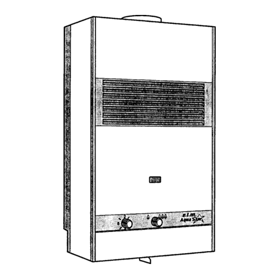
I N S TA L L AT I O N A N D O P E R AT I N G I N S T R U C T I O N S
F O R A U T O M AT I C I N S TA N TA N E O U S T Y P E WAT E R H E AT E R S
F O R U S E W I T H N AT U R A L A N D L I Q U E F I E D P E T R O L E U M G A S
MODEL 125 VP AND MODEL 125 VPS
Suitable for water (potable) heating and space heating
Upon completion of the installation, these instructions should be handed to the user of the appliance for
future reference.
*REPLACEMENT MANUAL MUST BE PURCHASED
FEATURING:
Variable Power - Modulating Gas Valve - Thermostatic Control with Temperature Dial Selector
WARNING:
If the information in this manual is not
followed exactly, a fire or explosion may result
causing property damage, personal injury or death.
FOR YOUR SAFETY
Do not store or use gasoline or other flammable,
combustible or corrosive vapors and liquids in
the vicinty of this or any other appliance.
WHAT TO DO IF YOU SMELL GAS
•
Do not try to light any appliance.
• Do not touch any electrical switch; do not use
any phone in your building.
• Immediately call your gas supplier from a
neighbor's phone. Follow the gas supplier's
instructions.
• If you cannot reach your gas supplier, call the
fire department.
- Installation and service must be performed
by a qualified installer, service agency or
the gas supplier.
Advertisement

Related Manuals for AquaStar 125 VP


Summary of Contents for AquaStar 125 VP
- Page 1 F O R U S E W I T H N AT U R A L A N D L I Q U E F I E D P E T R O L E U M G A S MODEL 125 VP AND MODEL 125 VPS...
-
Page 2: Table Of Contents
TABLE OF CONTENTS Specifications ................Page Rules for Safe Operation ............. Page General Overview of Aquastar ............ Page Locating the Heater for Safe Proper Combustion ......Page Installation ................... Page Connecting Gas and Water Lines & Pressure Relief Valve ..Page 9-10 Vent Pipe Connection .............. - Page 3 AquaStar 125 VP and 125 VP "S" Specifications: Gas input........max: 125,000 Btu min: 25,000 Btu Water Connection......1/2" sweat fitting H x W x D.........27.5" x 17" x 9.5" Vent...............5" Gas Connection......3/4" NPT thread Min. Water Pressure........15 Psi Max. Water Pressure........150 Psi Shipping Weight..........43 lb...
- Page 4 CAUTION: RULES FOR SAFE OPERATION If you are using the AquaStar for combined space heating and potable water heating ( see schematic diagram below), all piping and other components connected to the system must be suitable for potable water, (b) toxic chemicals such as those commonly used for boiler...
-
Page 5: Rules For Safe Operation
RULES FOR SAFE OPERATION 1. You should follow these instructions when you 6. Keep water heater area clear and free from install your heater. combustibles and flammable liquids. Do not lo- In the United States: The installation must con- cate the heater over any material which might form with local codes or, in the absence of local burn, such as carpet. - Page 6 Fig. 2 Parts of AquaStar 125 A. hanging frame and back hot water outlet T. pilot support V. overheat shut off sensor J. thermostat adjustment screw B. thermostatic sensor W. draft hood K. gas inlet C. heat exchanger X. rating plate-serial # L.
- Page 7 That would be 6250 cubic feet 6. Having a floor drain or sink nearby is handy in for the AquaStar 125 alone. case you need to drain water from your heater. b) In unconfined spaces in buildings of conventional frame, masonry, or metal 7.
-
Page 8: Installation
7. This heater is not approved for closet installa- heater. Use the adhesive tape which is included tion. For alcove installation, maintain the follow- in the package to stick the pattern to the wall. ing minimum clearances from all construction for Keep in mind that the heater needs to have cer- servicing and proper operations: tain minimum clearances (See paragraph 7 on... - Page 9 20 feet and serves only the that piping and water pressure must allow suffi- AquaStar, it can be reduced to 5/8". When cient flow to activate the heater when drawing hot threading the gas pressure regulator to the gas water from the top floor.
-
Page 10: Vent Pipe Connection
Sweat your cold water pipe to the AquaStar inlet develop a positive flow adequate to remove flue elbow fitting. NOTE: The inlet filter screen and gasses to the outdoors under all operating con- water flow restrictor can be damaged by heat ditions. -
Page 11: Lighting Instructions
"RED FLAME" position. Push in center PILOT LIGHTING knob on the front of the TO TURN OFF GAS TO APPLIANCE AquaStar and twist counterclockwise Turn gas control shut off handle to the "RED DOT" .Push knob all the way in and hold it symbol. - Page 12 Remember you can- restrictor set at 3 1/4 gpm. Its purpose is to as- not run out of hot water with an AquaStar, so set sure that the hot water temperature will always the dial for the (exact) temperature that you need.
- Page 13 Fig. 4 Characteristic Pilot Flame air. If installed near a dryer, make sure the dryer is properly vented, and that the AquaStar vents To clean the pilot:Turn off the gas at the unit properly when the dryer is operating.
- Page 14 A. Gas cock on gas line may not be open. B. AquaStar manual shut off valve at base of the smaller right hand pilot flame touches the ther- heater is not open. Turn handle to red flame sym- mocouple tip.
- Page 15 4. Pilot orifice may not be correct for your 3. Poor circuit connections at the ECO type of gas. (Energy Cut-Off) Pilot orifice is stamped: #18 for LP and #35 for Oxidation or looseness of the ECO screw con- nections can result in millivolt current loss through the thermocouple safety circuit.
- Page 16 If the reading is 24 mv or over, the thermocouple sure in the system preventing the pressure drop is good. in the AquaStar - i.e. cold water is entering the To test the electromagnet, reconnect the thermo- water valve from both sides and the burners will couple and take another reading.
-
Page 17: Setting Water Temperature
3. Unlike storage tank water heaters, the cold water, an AquaStar can be set for the exact burners of a tankless water heater must be very temperature needed and give endless hot water powerful to heat water instantaneously since they without need for mixing in cold water. - Page 18 AquaStar and the outlet HOT WATER TEMPERATURE FLUCTUATES Compare water temperature at outlet of the AquaStar with the temperature at the tap. If dif- 1. Temperature setting is too high ferent, check for automatic mixing valve or plumb-...
-
Page 19: Cleaning Pilot Assembly
CLEANING THE PILOT ASSEMBLY suspect that it might be partially obstructed. If you do AquaStar models 80/125/170 not have a replacement orifice, you may blow through it or use a non-residue aerosol cleaning agent (like A. Removing Pilot that used for electronics) can be sprayed through 1.Hold Gas Pilot Filter Housing in place with one... -
Page 20: Calibration And Thermostat Test
1. Turn AquaStar temperature setting to #8. This is all the way to the right, clockwise. 2. Turn on a hot water tap at the flow which will turn the AquaStar burners on. If the heater is working correctly, this minimum activation flow will be 3/4 of a gallon a minute, for Model 125/80 and 1.1 for Model 170. - Page 21 PROCEDURE FOR REPLACING A THERMOSTAT 5. Pull down on the thermostat 1. Insert the capillary sensor into the TO REMOVE THERMOSTAT: piston assembly to remove it from heat exchanger. Be sure that the rub- the gas valve. ber gasket seats properly and then A.
- Page 22 The appliance Gas Regulator (#24) at the inlet to the This permits the AquaStar 80/125 vpS to work heater ensures that gas pressure fluctuations don’t over- effectively and safely with pre-heated water.
- Page 23 DIAGRAMATIC LAYOUT WATER TEMPERATURE PROBE (THERMOSTAT 9. PILOT LIGHT 1 . HEAT EXCHANGER SENSOR) 10. PILOT LIGHT ORIFICE 2. BURNERS 18. GAS LINE PRESSURE TEST NIPPLE 11. PILOT LIGHT GAS FILTER 3. WATER FLOW RESTRICTOR 19. OVERHEAT SENSOR SWITCH 12. THERMOCOUPLE 4.
- Page 24 HOUSING COMPONENTS DIAGRAM AQUASTAR 125 38799 38798 34353 22527 28329 23617 23617 34224 SPARE PARTS LIST 23617 - PANEL RETAINING SCREW 38798 - RIGHT SIDE PANEL 34353 - FRONT PANEL 38799 - LEFT SIDE PANEL 28329 - PILOT STARTER KNOB...
- Page 25 INTERIOR COMPONENTS DIAGRAM AQUASTAR 125 SPARE PARTS LIST 00839 - PILOT INJECTOR WASHER 22349 - SCREW 34240 - NG GAS REGULATOR 00869 - RETAINING NUT FOR GAS INLET FITTING 22349 - REAR BURNER SHIELD RETAINING SCREW 34296 - WATER & GAS FITTINGS RETAINING STRIP...
- Page 26 VALVE ASSEMBLY COMPONENTS DIAGRAM AQUASTAR 125 37167 23617 Ng 39580 LPg 20775 Ng 36650 LPg34539 Ng 39581 32959 22043 Ng 33217 "S" NATURAL GAS NG COMPLETE ASSEMBLY 36589 "S" PROPANE LP GAS COMPLETE ASSEMBLY 36590 N A T U R A L G A S N G C O M P L E T E A S S E M B L Y 3 4 3 4 8...
- Page 27 INSTALLATION CHECKLIST Gas Line Size* Natural Gas Nominal Iron Pipe Size* 1/2" 3/4" 1" Model 80 25" 100' 150' 125' Liquid Propane Semi-rigid Tubing 1/2" 5/8" 3/4" 7/8" Model 100' 100' *Flex tubing greatly reduces capacity and, therefore, is not recommended. Minimum Vent Size* and Height Model Min.
- Page 28 MISCELLANEAOUS you selected by CEC, such as a local AQUASTAR dealer or distributor. No one is authorized to make any other warranties on behalf of CEC. IT IS EXPRESSLY UNDERSTOOD THAT THE REPLACEMENT...
Need help?
Do you have a question about the 125 VP and is the answer not in the manual?
Questions and answers