Table of Contents

Subscribe to Our Youtube Channel
Related Manuals for Kutai electronics ATS-380


Summary of Contents for Kutai electronics ATS-380
- Page 1 ATS-380 Ver1.0 UTOMATIC RANSFER WITCH CONTROL UNIT OPERATOR’S MANUAL Headquarters : No.3, Lane 201, Chien Fu ST., Chyan Jenn Dist., Kaohsiung, TAIWAN Tel : + 886-7-8121771 Fax : + 886-7-8121775 URL : http://www.kutai.com.tw...
-
Page 2: Table Of Contents
ATS-380 Automatic Transfer Switch TABLE OF CONTENTS Section Page SECTOIN 1 : INTRODUCTION 1.1 Preliminary Comments and Safety Precautions ................3 1.2 Overview ............................3 1.3 Product Overview..........................3 1.4 Functions / Features ........................4 SECTOIN 2 : HARDWARE DESCRIPTION 2.1 General............................. -
Page 3: Preliminary Comments And Safety Precautions
Switch functions were Automatic Transfer Switch Controller. It is provided performed by a door mounted logic panel ATS-380 as a guide for authorized and qualified personnel control unit. The ATS-380 logic panel brings application of the ATS-380 Automatic Transfer intelligence,... -
Page 4: Functions / Features
TDES timer will 1.4 Functions / Features reset. The ATS-380 controller can perform the time delay engine start function without control power for The primary function of ATS-380 controller is to 30 seconds. ( Refer to program line 7.) - Page 5 The interval is fixed at once per week with a specific test day and time. The test period is FAIL on the front panel of the ATS-380 indicates that also programmable by customer setting. The a transfer was initiated but never completed. This...
-
Page 6: General
LEDs refer to Paragraph 3.4. 2.5 Rear Access Area (Refer to Figure 2) The rear access area of the ATS-380 controller is normally accessible from the rear of panel. A wiring connection to the ATS-380 controller is made at the rear of the chassis. -
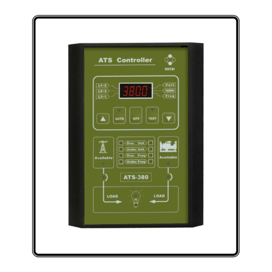
Page 7: Front Panel
ATS-380 Automatic Transfer Switch Front Panel Display Window Operator Pushbutton ATS status LEDs Figure 1 ______________________________________________________________________________________... - Page 8 ATS-380 Automatic Transfer Switch Rear Area 9 10 Figure 2 ______________________________________________________________________________________...
-
Page 9: Sectoin 3 : Operator Panel 3.1 General
The ATS-380 is provided with a test pushbutton that simulates a loss of normal source. Pushing the NOTICE TEST select key, the ATS-380 will run in engine test mode and a LED is provided to indicate the test Although a wide variety of parameters and position. -
Page 10: General
Indicates that the standby source is available and This section specifically describes the operation and voltage frequency within functional use of the ATS-380 controller. It is divided programmed parameters. into four main categories: Standby Source Connected ( Green ) ● Automatic mode Indicates that the transfer switch is connected to the ●... -
Page 11: Engine Test Mode
Pushing the & decrease (▼) ” on the front panel for 4 seconds. TEST key on the front of panel, the ATS-380 will run The word “ Ver 1.0 ” will appear on the front display in engine test mode. - Page 12 ATS-380 Automatic Transfer Switch * * * * LINE BY LINE PROGRAMMING TABLE Factory LINE DESCRIPTION VALUE Setting Key in the real volt of normal side R & T 380V System voltage setting ( 250V ~ 500V ) 1) 1Ø 2) 3Ø...
-
Page 13: Specification Summary
° C ~ 85 Storage Temperature 0 to 95% relative humidity Operating Humidity SECTION 5 : INSTALLATION INSTRUCTIONS 5.1 General The ATS-380 controller has been designed for front panel mounting. 5.2 Panel Cut-Out ( All Dimensions in MM. ) ______________________________________________________________________________________... -
Page 14: Unit Dimensions
The ATS-380 maximum transfer current is 6 Amps,. 6.1 General When the switch transfer current over 6 Amps, two It is dangerous to feed high voltage to the ATS-380 external power relays is recommended. ( The Printed Circuit boards. The ATS-380 controller connecting wire diagram refer to 6.5 section. -
Page 15: 3Phase 3Wire Connecting Wire Diagram
ATS-380 Automatic Transfer Switch 6.2 4P 380V Connecting Wire Diagram 6.2.1 MCCB Type Wiring Diagram MOTOR ATS-380 CONTROL UNIT ______________________________________________________________________________________... - Page 16 ATS-380 Automatic Transfer Switch 6.2.2 One Coil Double Throw Typical Wiring Diagram ATS-380 CONTROL UNIT ______________________________________________________________________________________...
- Page 17 ATS-380 Automatic Transfer Switch 6.2.3 Two Coils Double Throw Type Wiring Diagram ATS-380 CONTROL UNIT ______________________________________________________________________________________...
- Page 18 ATS-380 Automatic Transfer Switch 6.2.4 Magnetic Contactor Type Wiring Diagram ATS-380 CONTROL UNIT ______________________________________________________________________________________...
-
Page 19: 1Phase 3Wire Connecting Wire Diagram
ATS-380 Automatic Transfer Switch 6.3 3P 380V Connecting Wire Diagram 6.3.1 MCCB Type Wiring Diagram MOTOR Normal Phase N Emergency Phase N ATS-380 CONTROL UNIT ______________________________________________________________________________________... - Page 20 ATS-380 Automatic Transfer Switch 6.3.2 One Coil Double Throw Typical Wiring Diagram Normal Phase N Emergency Phase N ATS-380 CONTROL UNIT ______________________________________________________________________________________...
- Page 21 ATS-380 Automatic Transfer Switch 6.3.3 Two Coils Double Throw Type Wiring Diagram Normal Phase N Emergency Phase N ATS-380 CONTROL UNIT ______________________________________________________________________________________...
- Page 22 ATS-380 Automatic Transfer Switch 6.3.4 Magnetic Contactor Type Wiring Diagram Normal Phase N Emergency Phase N ATS-380 CONTROL UNIT ______________________________________________________________________________________...
-
Page 23: Single Phase Connecting Wire Diagram
ATS-380 Automatic Transfer Switch 6.4 Single Phase 380V Connecting Wire Diagram 6.4.1 MCCB Type Wiring Diagram MOTOR Normal Phase N Emergency Phase N ATS-380 CONTROL UNIT ______________________________________________________________________________________... - Page 24 ATS-380 Automatic Transfer Switch 6.4.2 One Coil Double Throw Typical Wiring Diagram Normal Phase N Emergency Phase N ATS-380 CONTROL UNIT ______________________________________________________________________________________...
- Page 25 ATS-380 Automatic Transfer Switch 6.4.3 Two Coils Double Throw Type Wiring Diagram Normal Phase N Emergency Phase N ATS-380 CONTROL UNIT ______________________________________________________________________________________...
- Page 26 ATS-380 Automatic Transfer Switch 6.4.4 Magnetic Contactor Type Wiring Diagram Normal Phase N Emergency Phase N ATS-380 CONTROL UNIT ______________________________________________________________________________________...
-
Page 27: Connecting Wire Diagram When The Transfer Current Over 6 Amps
ATS-380 Automatic Transfer Switch 6.5 Connecting Wire Diagram When The Switch Transfer Current Over 6 Amps 6.5.1 MCCB Type Wiring Diagram MOTOR ATS-380 CONTROL UNIT ______________________________________________________________________________________... - Page 28 ATS-380 Automatic Transfer Switch 6.5.2 One Coil Double Throw Typical Wiring Diagram ATS-380 CONTROL UNIT ______________________________________________________________________________________...
- Page 29 ATS-380 Automatic Transfer Switch 6.5.3 Two Coils Double Throw Type Wiring Diagram ATS-380 CONTROL UNIT ______________________________________________________________________________________...
- Page 30 ATS-380 Automatic Transfer Switch 6.5.4 Magnetic Contactor Type Wiring Diagram ATS-380 CONTROL UNIT ______________________________________________________________________________________...
Need help?
Do you have a question about the ATS-380 and is the answer not in the manual?
Questions and answers