Table of Contents
Advertisement
Quick Links
Advertisement
Table of Contents

Subscribe to Our Youtube Channel
Related Manuals for Kutai electronics ATS-PLC


Summary of Contents for Kutai electronics ATS-PLC
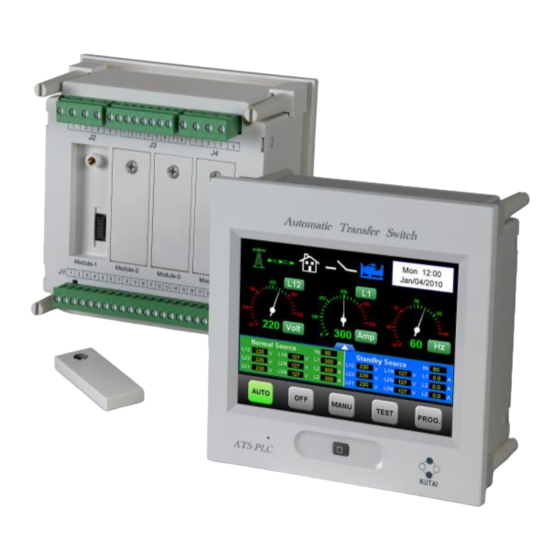
- Page 1 ATS-PLC Ver1.0 Programmable Touch-Screen Automatic Transfer Switch Control Unit Operation Manual KUTAI ELECTRONICS INDUSTRY CO., LTD. TEL : +886-7-8121771 FAX : +886-7-8121775 Website : www.kutai.com.tw Headquarters : No.3, Ln. 201, Qianfu St., Qianzhen Dist., Kaohsiung City 80664, Taiwan...
-
Page 2: Table Of Contents
1.3 Product Overview............................3 1.4 Functions / Features ........................... 3 1.5 Electrical Characteristics ..........................4 1.6 Exterior Overview............................5 1.7 ATS-PLC Quickly Start ..........................6 SECTOIN 2 : TOUCH SCREEN PANEL OVERVIEW 2.1 Status Icons ..............................8 2.2 Start-Up Screen ............................8 2.3 AUTO Mode .............................. -
Page 3: Preliminary Comments And Safety Precautions
● 5.7” inch color LCD touch-screen. manual covers installation, operation maintenance of the ATS-PLC Automatic Transfer ● Program and function setting via touch-screen Switch Controller. This manual is for use by authorized operation. and qualified personnel only. ● Voltage, current, frequency and KVA readings for normal and standby power and current time display. -
Page 4: Electrical Characteristics
Communications Transmission ITEM SETTING RANGE FACTORY PRESET Remote Operation Enable/Disable Disable Baudrate 1200 / 2400 / 9600 / 19200 / 38400 / 57600 38400 00 99 (Valid value 01 99;00 Disabled) RS485 Slave Address 00 (Disabled) ___________________________________________________________________________________________ ATS-PLC... -
Page 5: Exterior Overview
LED (Blinking) Home Button Press to return to main page at anytime Press and hold for 10 sec to execute touch screen sensitivity adjustment function Rear Removable DIN terminals Terminal Number Communication Expansion Sockets Removable DIN terminal Mounting Hole ___________________________________________________________________________________________ ATS-PLC... -
Page 6: Ats-Plc Quickly Start
1.7 ATS-PLC Quickly Start Step1 : Refer to chapter-5 (wiring diagram) for Step5:Select Language. (Refer to 2.7.3.2) completed wiring. Step2:Turn on the DC power and set the ATS-PLC controller under OFF mode. Step6:Setting system phase and CT rated. (Refer to 2.7.5.1) Step3:Into programming mode. - Page 7 Step10:Power on Normal side AC volt input and set Step13:Repeat Step 11 & 12 to make sure the ATS the ATS-PLC under Manual mode. works or not. Step14:Set the ATS-PLC on AUTO mode and finished the quick start procedure. ___________________________________________________________________________________________ ATS-PLC...
-
Page 8: Sectoin 2 : Touch Screen Panel Overview
Incorrect password entered. System locked (Please contact with dealer) 2.2 Start-up Screen Start-up Screen Displays for 3 sec then enters operation mode Press to skip start-up screen Attention! Start-up screen is customizable by user, for details please refer to APPENDIX 02. ___________________________________________________________________________________________ ATS-PLC... -
Page 9: Auto Mode
3 Phase 4 Wires selection sequence = L12 > L23 > L31 > L1N > L2N > L3N Note 02 Volt / Amp / Frequency display sequence = Volt > Amp > Hz 2.3.2 Numerical Meter Mode Main Screen Connection Status Press to change back to analog display Normal Source Readings Standby source Readings ___________________________________________________________________________________________ ATS-PLC... -
Page 10: Off Mode
Listed in order of occurrence Move up Move down Return to last page Home Key Press to Return to OFF Screen Attention! If controller left untouched or no entries being selected in 60 seconds the screen will automatically return to OFF screen. ___________________________________________________________________________________________ ATS-PLC... -
Page 11: Manual Mode
Engine Start / Stop button Normal Source Data Standby Source Data Display Area Display Area In MANUAL 2.5.2 Manual Mode Display Screen (Standby Source Supplying) ATS Connection Status Normal Source Manual Engine Start / Connect Button Stop Button ___________________________________________________________________________________________ ATS-PLC... -
Page 12: Test Mode
When executing Test while emergency source is connected, system will bypass “ With Load / Without Attention! Load Selection ” and exercise testing with load. 2.6.2 With Load Testing Screen Display Blue Represents the Currently Displayed Parameter for Standby Source ___________________________________________________________________________________________ ATS-PLC... -
Page 13: Program Mode
Time Delay OV/UV Setting Protection Setup Standby OV/UV Setting OV/UV Reset Time Delay OF/UF Setting Standby OF/UF Setting OF/UF Reset Time Delay Reverse Phase Sequency Normal V Calibration Calibrated V/A Reading Load A Calibration Factory Setting Standby V Calibration ___________________________________________________________________________________________ ATS-PLC... - Page 14 If controller left untouched or no entries being selected in 60 seconds the screen will automatically return to OFF mode display screen. 2.7.2 Enter Program Mode Procedure Error Warning Error Message Mute Attention! The error message is displayed for 5 seconds only, and then automatically returns to previous screen. ___________________________________________________________________________________________ ATS-PLC...
- Page 15 Attention! The adjustment of system clock directly affects the automatic exerciser test and event log records, therefore it is vital to setup the correct current time and date when install the unit for the first time. ___________________________________________________________________________________________ ATS-PLC...
- Page 16 2.7.3.2 Language Setting Currently ATS-PLC operating language only support traditional English and Spanish. When selected the back ground turns blue When selecting the language it turns blue 2.7.3.3 Passcode Setting Return to last page button (Modification are not saved if pressed)
- Page 17 Once passcode is set, to change or disable the passcode, enter “System Setup” and click “Passcode”. Change Passcode Disable Passcode 2.7.3.5 Brightness Adjustment Brightness Backlight adjustment buttons Screen Saver time. When set to maximum, the Brightness Adjustment screen saver mode will be cancelled. ___________________________________________________________________________________________ ATS-PLC...
- Page 18 Communication Interface Setting General Description Download Startup Screen Attention! For Startup Screen download program, please refer to Appendix 02. 2.7.4.1 Remote Communication Interface Setting Enable / Disable ATS-PLC Remote Communication Baud Rate Setting RS485 Address Setting ___________________________________________________________________________________________ ATS-PLC...
- Page 19 2.7.5 System Parameter Setting System Parameter Setting General Description 2.7.5.1 System Power Setting System Power Setting Phase Selection CT Setting Range : 50 ~ 6000 / 5A ___________________________________________________________________________________________ ATS-PLC...
- Page 20 All time delay setting is 2 seconds per Unit. 2.7.5.3 Transfer Switch Type Setting Transfer Switch type Selection Blue represents the type selected Transfer Switch Type Setting Attention! When inconsistent transfer Switch is selected, may cause the ATS fails to operate. ___________________________________________________________________________________________ ATS-PLC...
- Page 21 Exerciser Enabled Day : 1 = MON, 2 = TUE Hour : 24hrs Exercise with / without load Minutes : 00 to 59 Schedule Interval Exercise Duration : 0 to 120 Range: 1 to 4 weeks Unit : Minute ___________________________________________________________________________________________ ATS-PLC...
- Page 22 2.7.5.5 Voltage, Frequency Protection and Voltage and Current Reading Adjustment Normal OV/UV/OF/UF General Description Standby OV/UV/OF/UF Reverse Phase Voltage and Current Reading Adjustment Voltage and Current Adjustment Load Current Adjustment Normal Source Standby Source Voltage Adjustment Voltage Adjustment ___________________________________________________________________________________________ ATS-PLC...
- Page 23 This screen is displayed in 3 Phase 4 Wire system voltage setting only. 2.7.5.6 Reset to Factory Setting / Default Factory Reset Resetting Parameters Confirmation to Factory Default Attention! When execute factory reset, all modified system parameters will be override to factory preset / default setting. ___________________________________________________________________________________________ ATS-PLC...
- Page 24 MODULE SETTING Step 1:Remove slot cover from the back of controller. By installing the KCU-XX modules (EX : KCU-01, KCU-02, KCU-03..etc.) to the ATS-PLC, user can operate or monitor the generator remotely. ● KCU-01 – USB communication module ● KCU-02 – RS-485 communications module ●...
- Page 25 ___________________________________________________________________________________________ ATS-PLC...
-
Page 26: Sectoin 4 : Specification And Installation
Alarm Output Contact 7A @ 250 Vac Max Operating Temperature -20 to +60 Storage Temperature -30 to +80 Operating Humidity Maximum 90% relative humidity Weight 750 g +/- 2% 4.2 Unit Dimension and Installation Reference (Unit: mm) ___________________________________________________________________________________________ ATS-PLC... -
Page 27: Section 5 : Typical Wiring
SECTION 5 : TYPICAL WIRING 5.1 MCCB Type ATS Wiring Diagram (3P/4P 220 Vac) also called the BTS switch ___________________________________________________________________________________________ ATS-PLC... - Page 28 5.2 MCCB Type ATS Wiring Diagram (2P 220 Vac) ___________________________________________________________________________________________ ATS-PLC...
- Page 29 5.3 MOT Type ATS Wiring Diagram (3P/4P 220 Vac) Motor Operated MCCB ___________________________________________________________________________________________ ATS-PLC...
- Page 30 5.4 MOT Type ATS Wiring Diagram (2P 220 Vac) ___________________________________________________________________________________________ ATS-PLC...
- Page 31 5.5 Air Circuit Breaker Type ATS Wiring Diagram (3P/4P 220 Vac) ___________________________________________________________________________________________ ATS-PLC...
- Page 32 5.6 Air Circuit Breaker Type ATS Wiring Diagram (2P 220 Vac) ___________________________________________________________________________________________ ATS-PLC...
- Page 33 5.7 Single Coil Double Throw Type ATS Wiring Diagram (3P/4P 220 Vac) ___________________________________________________________________________________________ ATS-PLC...
- Page 34 5.8 Single Coil Double Throw Type ATS Wiring Diagram (2P 220 Vac) ___________________________________________________________________________________________ ATS-PLC...
- Page 35 5.9 Dual Coil Double Throw Type ATS Wiring Diagram (3P/4P 220 Vac) ___________________________________________________________________________________________ ATS-PLC...
- Page 36 5.10 Dual Coil Double Throw Type ATS Wiring Diagram (2P 220 Vac) ___________________________________________________________________________________________ ATS-PLC...
- Page 37 5.11 KUTAI TS-XXX Type ATS Wiring Diagram (3P/4P 220 Vac) ___________________________________________________________________________________________ ATS-PLC...
- Page 38 5.12 KUTAI TS-XXX Type ATS Wiring Diagram (2P 220 Vac) ___________________________________________________________________________________________ ATS-PLC...
- Page 39 5.13 KME WN Type and AICHI WN type ATS Wiring Diagram (3P/4P 220 Vac) ___________________________________________________________________________________________ ATS-PLC...
- Page 40 5.14 KME WN Type and AICHI WN type ATS Wiring Diagram (2P 220 Vac) ___________________________________________________________________________________________ ATS-PLC...
- Page 41 5.15 SOCOMEC ATyS-3S type ATS Wiring Diagram (3P/4P 220 Vac) ___________________________________________________________________________________________ ATS-PLC...
- Page 42 5.16 SOCOMEC ATyS-3S type ATS Wiring Diagram (2P 220 Vac) ___________________________________________________________________________________________ ATS-PLC...
- Page 43 5.17 SOCOMEC ATyS-3e type ATS Wiring Diagram (3P/4P 220 Vac) ___________________________________________________________________________________________ ATS-PLC...
- Page 44 5.18 SOCOMEC ATyS-3e type ATS Wiring Diagram (2P 220 Vac) ___________________________________________________________________________________________ ATS-PLC...
- Page 45 5.19 SOCOMEC ATyS-6 type ATS Wiring Diagram (3P/4P 220 Vac) ___________________________________________________________________________________________ ATS-PLC...
- Page 46 5.20 SOCOMEC ATyS-6 type ATS Wiring Diagram (2P 220 Vac) ___________________________________________________________________________________________ ATS-PLC...
- Page 47 5.21 SOCOMEC ATyS-6e type ATS Wiring Diagram (3P/4P 220 Vac) ___________________________________________________________________________________________ ATS-PLC...
- Page 48 5.22 SOCOMEC ATyS-6e type ATS Wiring Diagram (2P 220 Vac) ___________________________________________________________________________________________ ATS-PLC...
- Page 49 5.23 MITSUBISHI MD type ATS Wiring Diagram (3P/4P 220 Vac) ___________________________________________________________________________________________ ATS-PLC...
- Page 50 5.24 MITSUBISHI MD type ATS Wiring Diagram (2P 220 Vac) ___________________________________________________________________________________________ ATS-PLC...
- Page 51 5.25 MERLIN GERIN MCB type ATS Wiring Diagram (3P/4P 220 Vac) ___________________________________________________________________________________________ ATS-PLC...
- Page 52 5.26 MERLIN GERIN MCB type ATS Wiring Diagram (2P 220 Vac) ___________________________________________________________________________________________ ATS-PLC...
- Page 53 5.27 System Voltage different From AC220V wiring Diagram ___________________________________________________________________________________________ ATS-PLC...
-
Page 54: Appendix 01 : Touch Screen Sensitivity Calibration
Step 5 : 3rd coordinate. Step 3 : first coordinate will first appear in the upper left-hand corner, aim for the center of the coordinate and press. Total of 7 coordinates needs to be calibrated Step 6 : 4th coordinate. ___________________________________________________________________________________________ ATS-PLC... - Page 55 If accidentally touched the screen or inaccurate adjustment is made during calibration, please completed the rest of calibration first before resuming to step 1 and recalibrate. Step 9 : 7th coordinate (last calibration). ___________________________________________________________________________________________ ATS-PLC...
-
Page 56: Appendix 02 : Download Start-Up Screen
APPENDIX 02 : Download Start-up Screen When powering up the ATS-PLC, the system will display a customizable start-up screen. This chapter will provide you with the step by step instruction on how to setup customizing start-up screen. Step 6 : Click on “Link” and select “Connect” to connect Note 1 : The Start-up Screen picture format is limited to bmp, jpg and png files only with image size 630*390. - Page 57 Step 12 : The controller will display the follow screen. “ATS-PLC Communication Interface”. Step 13 : Click on “Start” on PC screen to begin file Step 10 : Disable ATS-PLC communication function. download. Step 14 : File downloading. Step 11 : Return to Communication Setup and click “Download Image”.
- Page 58 USB connection. Attention! After image is downloaded (Step 15), if user wishes to change to other image, or download image to another controller, please remove USB connection from PC and re-plug it again and retrace back to Step ___________________________________________________________________________________________ ATS-PLC...
Need help?
Do you have a question about the ATS-PLC and is the answer not in the manual?
Questions and answers