Table of Contents
Advertisement
E2007 Lennox Industries Inc.
Dallas, Texas, USA
3 Heat / 2 Cool Programmable
This thermostat is to be installed by a qualified service technician or
other qualified agency in accordance with the manufacturer's instruc-
tions, all codes, and requirements of the authority having jurisdiction.
505,044M
8/2007
Touch Screen Thermostat
WARNING
INSTALLATION
INSTRUCTIONS
Advertisement
Table of Contents

Related Manuals for Lennox X4147


Summary of Contents for Lennox X4147
- Page 1 INSTALLATION INSTRUCTIONS E2007 Lennox Industries Inc. Dallas, Texas, USA 3 Heat / 2 Cool Programmable Touch Screen Thermostat WARNING This thermostat is to be installed by a qualified service technician or other qualified agency in accordance with the manufacturer’s instruc- tions, all codes, and requirements of the authority having jurisdiction.
-
Page 2: Table Of Contents
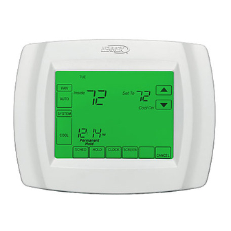
Troubleshooting ..Page 20 Electrical tape General Thermostat Location The Lennox X4147 programmable Install the thermostat about 5 feet touch-screen thermostat provides (1.5m) above the floor in an area with control for up to three stages of heating good air circulation. -
Page 3: Remove Existing Thermostat
carried on the replacement wall- Remove Existing Thermostat plate. If this thermostat is being used to re- Do not allow the thermostat wires place an existing thermostat, remove to fall behind the drywall. the old thermostat: 1 − Turn off power at the heating and/ WARNING or cooling system or fuse/circuit breaker panel. -
Page 4: Thermostat Installation
6 − Position the wallplate over the an- Thermostat Installation chors and pull the thermostat The thermostat may be installed hori- wires back through the wiring zontally in a 4 in. X 2 in. (101.6 mm X opening. 50.8 mm) wiring box or on the wall us- 7 −... -
Page 5: Led Indicator
1 − Make wiring connections per the the loosened screws. Securely appropriate wiring diagram on tighten each screw. page 6 or 7. Refer to the table TERMINAL below for terminal designations. BLOCK LETTER DESIGNATIONS Terminal Description Second−stage cooling WALLPLATE Second−stage heating W2 (AUX) (or auxiliary heating) WIRE HOLE... -
Page 6: Field Wiring Diagrams
Field Wiring Diagrams TYPICAL CONVENTIONAL MULTI−STAGE APPLICATION TWO−STAGE HEAT / TWO−STAGE COOL TYPICAL MULTI−STAGE HEAT PUMP APPLICATION NO AUXILIARY HEAT TYPICAL MULTI−STAGE HEAT PUMP APPLICATION WITH AUXILIARY HEAT Page 6... - Page 7 Field Wiring Diagrams (Continued) TYPICAL SINGLE−STAGE HEAT PUMP SYSTEM WITH AUXILIARY HEAT TYPICAL SINGLE−STAGE HEAT PUMP SYSTEM WITHOUT AUXILIARY HEAT Page 7...
-
Page 8: Install Batteries
WALLPLATE Install Batteries 1 − Install three provided AAA alkaline batteries in the back of the thermo- PINS ON stat as shown. BACK OF THERMOSTAT BACK OF THERMOSTAT TERMINAL SCREW BLOCK Set Calendar and Clock This thermostat is designed to auto- BATTERIES matically keep the current time and date in memory for up to ten years, un-... -
Page 9: Advanced Heat Pump Features
Heating Mode Operation Advanced Heat Pump Features Outdoor Temp. below Balance Point When the outdoor temperature is be- The thermostat installer set−up may be low the selected balance point, only configured in several different ways to the furnace (fossil fuel) operates to sat- ensure the desired system operation. - Page 10 Heat Pump Application When the outdoor temperature is Electric Auxiliary Heat above the auxiliary lock−out tempera- with Outdoor Temperature Sensor ture (balance point), only the compres- sor operates. Installer set−up number 0170 −− heat pump. When the outdoor temperature is be- tween the two temperatures, both the Installer set−up number 0200 −−...
-
Page 11: Installer Set−Up
Installer Set−Up Use the following steps and the Install- ADVANCE TO NEXT INSTALLER INSTALLER SET−UP er Set−Up menu to match the thermo- SET−UP NUMBER CURRENT stat to the HVAC system. SETTING 1 − Press and release the SYSTEM key. 2 − Press and hold the two blank keys on either side of the center blank key for approximately five sec- onds. - Page 12 Instal- Installer Selection Description lerSet− Set−Up Notes (Factory setting in bold print) Up No. Name Select first two digits of current calendar Date year (20 for 2007, etc.) 0120 (Year/ first) Factory setting = 20. Date Select last two digits of current calendar 0130 (Year/ year (07 for 2007, etc.);...
- Page 13 Instal- Installer Selection Description lerSet− Set−Up Notes (Factory setting in bold print) Up No. Name Available only if 0 − Gas or Oil Heat −− Heating system conventional controls fan during heating demand. system chosen. Factory setting. Control 0180 Setting defaults Heating to electric heat 1 −...
- Page 14 Instal- Installer Selection Description lerSet− Set−Up Notes (Factory setting in bold print) Up No. Name Cycles per Hour 1 − Recommended for use with steam and (cph) 2nd gravity. Stage Conven- 3 − Recommended for use with hot water tional heat and high−efficiency (90% or higher) Shown only Heating...
- Page 15 Instal- Installer Selection Description lerSet− Set−Up Notes (Factory setting in bold print) Up No. Name 0 − Manual changeover from heating mode to cooling mode. Factory setting. Change- 0300 over 1 − Auto−changeover from heating mode to cooling mode. 2 − 2°F (1.5°C) Dead- 3 −...
- Page 16 Instal- Installer Selection Description lerSet− Set−Up Notes (Factory setting in bold print) Up No. Name 0 − No auxiliary heat lock−out. Factory Shown only if setting. electric is se- Heat 40°F (4.5°C). lected for back− Pump up heat source 45°F (7°C) 0360 Auxiliary and outdoor...
- Page 17 Instal- Installer Selection Description lerSet− Set−Up Notes (Factory setting in bold print) Up No. Name Heat Settings of 40 − 90 available in 1°F in- Tempera- Shown in 1/2°C creme. 0600 ture increments Range Factory setting = 90.nts. (°F) Cool Settings of 50 −...
- Page 18 Instal- Installer Selection Description lerSet− Set−Up Notes (Factory setting in bold print) Up No. Name 1 − Less aggressive control. (Cooling may Cooling turn off before setpoint reached). Mode Applies to re- 2 − Standard control. Factory setting. 0690 Tempera- covery ramp.
-
Page 19: System Test
System Test The system test function allows the in- 4 − The installer test number is dis- staller to check the HVAC system after played on the upper portion of the the thermostat set−up has been com- screen. Press the up or down ar- pleted. -
Page 20: Troubleshooting
Troubleshooting Symptom Possible Cause Action 1− Check to see that there is 24V between R and C terminals. Display does not come Thermostat is not being powered. 2− Check to see that bat- teries are properly installed. 1− Check temperature set- points.
Need help?
Do you have a question about the X4147 and is the answer not in the manual?
Questions and answers
should the breaker be off before doing this? Align the terminal blocks on thewallplate with the pins on the backof thermostat.2 − Push the thermostat straight ontothe pins until it snaps into place.3 − Turn on power at the furnace or airhandler or at the fuse or circuitbreaker
Yes, the breaker should be off before installing the Lennox thermostat with part number X4147.
This answer is automatically generated
the light does not come on by touch either with batteries or wiring
The Lennox X4147 thermostat light does not turn on when powered by batteries alone or when 24Vac power is interrupted. This means that the indicator requires 24Vac power to function properly. If the thermostat is not lighting up, check if the 24Vac power supply is connected and working. If using batteries, ensure they are installed correctly, but note that the light will not turn on with battery power alone.
This answer is automatically generated
The light on the thermostat display stays on all the time. It used to only light when you pressed buttons on the display, but now, it stays on all the time. I disconnected the unit and changed the batteries, reset the breakers, none of these steps have helped. Any other troubleshooting steps or thoughts on what the issue may be and how to resolve?