Panasonic NN-CS596S BPQ Service Manual
Nn-cs596s series microwave oven
Hide thumbs
Also See for NN-CS596S BPQ:
- Operating instruction and cook book (254 pages) ,
- Service manual (8 pages)
Table of Contents
Advertisement
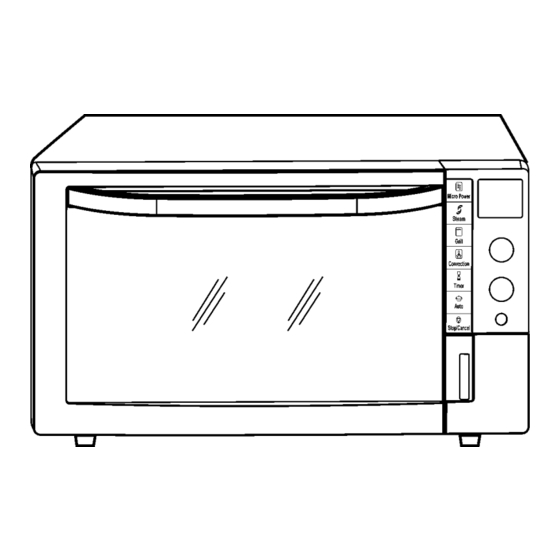
NN-CS596S
BPQ (U.K.)
EPG (France, Italy, Spain, Portugal, Greece, Poland,
Holland)
WPG (Switzerland)
SPG (Norway, Finland, Sweden, Denmark)
© 2006 Panasonic Home Appliances Microwave
Oven (Shanghai) Co., Ltd. All rights reserved.
Unauthorized copying and distribution is a violation
of law.
ORDER NO.PHAMOS0610046C2
Microwave Oven
Advertisement
Table of Contents
Troubleshooting


Need help?
Do you have a question about the NN-CS596S BPQ and is the answer not in the manual?
Questions and answers